Table of Contents

Subscribe to Our Youtube Channel
Related Manuals for EWM Taurus **5 Basic S Series


Summary of Contents for EWM Taurus **5 Basic S Series
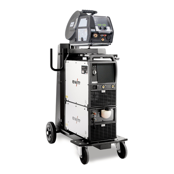
- Page 1 Operating instructions Welding machine Taurus 405 Basic S Taurus 505 Basic S Taurus 405 Steel Synergic S Taurus 505 Steel Synergic S Taurus 405 Steel puls S Taurus 505 Steel puls S 099-005589-EW501 Observe additional system documents! 20.03.2019...
- Page 2 +49 2680 181-0. A list of authorised sales partners can be found at www.ewm-group.com/en/specialist-dealers. Liability relating to the operation of this equipment is restricted solely to the function of the equipment. No other form of liability, regardless of type, shall be accepted.
-
Page 3: Table Of Contents
Contents Notes on the use of these operating instructions Contents 1 Contents ..............................3 2 For your safety ............................6 Notes on the use of these operating instructions ................6 Explanation of icons ........................7 Part of the complete documentation ....................8 Safety instructions .......................... - Page 4 Contents Notes on the use of these operating instructions 5.3.8 Notes on the installation of welding current leads ............26 5.3.9 Stray welding currents ....................27 MIG/MAG welding ........................28 5.4.1 Connection for workpiece lead ..................28 5.4.2 Welding torch connection ..................... 28 5.4.3 Welding task selection ....................
- Page 5 Contents Notes on the use of these operating instructions 099-005589-EW501 20.03.2019...
-
Page 6: For Your Safety
For your safety Notes on the use of these operating instructions For your safety Notes on the use of these operating instructions DANGER Working or operating procedures which must be closely observed to prevent imminent serious and even fatal injuries. •... -
Page 7: Explanation Of Icons
For your safety Explanation of icons Explanation of icons Symbol Description Symbol Description Indicates technical aspects which the Activate and release / Tap / Tip user must observe. Switch off machine Release Switch on machine Press and hold Switch Incorrect / Invalid Turn Numerical value –... -
Page 8: Part Of The Complete Documentation
For your safety Part of the complete documentation Part of the complete documentation These operating instructions are part of the complete documentation and valid only in combination with all other parts of these instructions! Read and observe the operating instructions for all system components, especially the safety instructions! The illustration shows a general example of a welding system. -
Page 9: Safety Instructions
For your safety Safety instructions Safety instructions WARNING Risk of accidents due to non-compliance with the safety instructions! Non-compliance with the safety instructions can be fatal! • Carefully read the safety instructions in this manual! • Observe the accident prevention regulations and any regional regulations! •... - Page 10 For your safety Safety instructions WARNING Explosion risk! Apparently harmless substances in closed containers may generate excessive pressure when heated. • Move containers with inflammable or explosive liquids away from the working area! • Never heat explosive liquids, dusts or gases by welding or cutting! Fire hazard! Due to the high temperatures, sparks, glowing parts and hot slag that occur during welding, there is a risk of flames.
- Page 11 For your safety Safety instructions CAUTION According to IEC 60974-10, welding machines are divided into two classes of electromagnetic compatibility (the EMC class can be found in the Technical data) > see 8 chapter: Class A machines are not intended for use in residential areas where the power supply comes from the low-voltage public mains network.
- Page 12 For your safety Transport and installation The manufacturer's warranty becomes void if non-genuine parts are used! • Only use system components and options (power sources, welding torches, electrode holders, remote controls, spare parts and replacement parts, etc.) from our range of products! •...
-
Page 13: Transport And Installation
For your safety Transport and installation Transport and installation WARNING Risk of injury due to improper handling of shielding gas cylinders! Improper handling and insufficient securing of shielding gas cylinders can cause serious injuries! • Observe the instructions from the gas manufacturer and any relevant regulations concerning the use of compressed air! •... -
Page 14: Intended Use
Intended use Applications Intended use WARNING Hazards due to improper usage! The machine has been constructed to the state of the art and any regulations and standards applicable for use in industry and trade. It may only be used for the welding procedures indicated at the rating plate. -
Page 15: Documents Which Also Apply
3.3.1 Warranty For more information refer to the "Warranty registration" brochure supplied and our information regarding warranty, maintenance and testing at www.ewm-group.com! 3.3.2 Declaration of Conformity The labelled product complies with the following EC directives in terms of its design and construction: •... -
Page 16: Machine Description - Quick Overview
Machine description – quick overview Front view / rear view Machine description – quick overview Front view / rear view Figure 4-1 099-005589-EW501 20.03.2019... - Page 17 Machine description – quick overview Front view / rear view Item Symbol Description Carrying handle Ready for operation signal light Signal light on when the machine is switched on and ready for operation Main switch, machine on/off Connection socket, “+” welding current How to connect the accessories depends on the welding procedure.
-
Page 18: Design And Function
Design and function Transport and installation Design and function WARNING Risk of injury from electrical voltage! Contact with live parts, e.g. power connections, can be fatal! • Observe the safety information on the first pages of the operating instructions! • Commissioning must be carried out by persons who are specifically trained in handling power sources! •... -
Page 19: Ambient Conditions
Design and function Transport and installation 5.2.1 Ambient conditions Equipment damage due to contamination! Unusually high amounts of dust, acids, corrosive gases or substances can damage the machine (observe maintenance intervals). • Avoid large amounts of smoke, steam, oily fumes, grinding dust and corrosive ambient air! 5.2.1.1 In operation Temperature range of the ambient air:... -
Page 20: Transport And Installation
Design and function Transport and installation Transport and installation WARNING Risk of accident due to improper transport of machines that must not be lifted! Do not lift or suspend the machine! The machine can drop and cause injuries! The handles, straps or brackets are suitable for transport by hand only! •... -
Page 21: Workpiece Lead, General
Design and function Transport and installation 5.3.3 Workpiece lead, general CAUTION Risk of burning due to incorrect welding current connection! If the welding current plugs (machine connections) are not locked or if the workpiece connection is contaminated (paint, corrosion), these connections and leads can heat up and cause burns when touched! •... -
Page 22: Connecting The Intermediate Hose Package To The Power Source
Design and function Transport and installation 5.3.5 Connecting the intermediate hose package to the power source 5.3.5.1 Intermediate hose package strain relief Missing or incorrectly fitted strain relief! Connection sockets or connection plugs on the machine, or the intermediate tube package, may be damaged if the strain relief is missing or incorrectly fitted. -
Page 23: Intermediate Hose Package Connection
Design and function Transport and installation 5.3.5.2 Intermediate hose package connection With this machine series, the earth cable on the intermediate hose package must not be connected to the welding machine or wire feeder! Remove the earth cable or push back into the hose package! Some wire electrodes (e.g. -
Page 24: Welding Torch Holder
Design and function Transport and installation 5.3.6 Welding torch holder The item described in the following is part of the machine´s scope of delivery. Figure 5-4 Item Symbol Description Crossmember of the transport handle Torch holder Fixing screws (x 4) Fan-type lock washers •... -
Page 25: Mains Connection
Design and function Transport and installation 5.3.7 Mains connection DANGER Hazards caused by improper mains connection! An improper mains connection can cause injuries or damage property! • The connection (mains plug or cable), the repair or voltage adjustment of the device must be carried out by a qualified electrician in accordance with the respective local laws or national regulations! •... -
Page 26: Notes On The Installation Of Welding Current Leads
Design and function Transport and installation 5.3.8 Notes on the installation of welding current leads • Incorrectly installed welding current leads can cause faults in the arc (flickering). • Lay the workpiece lead and hose package of power sources without HF igniter (MIG/MAG) for as long and as close as possible in parallel. -
Page 27: Stray Welding Currents
Design and function Transport and installation 5.3.9 Stray welding currents WARNING Risk of injury due to stray welding currents! Stray welding currents can destroy protective earth conductors, damage machines and electronic devices and cause overheating of components, leading to fire. •... -
Page 28: Mig/Mag Welding
Design and function MIG/MAG welding MIG/MAG welding 5.4.1 Connection for workpiece lead Some wire electrodes (e.g. self-shielding cored wire) are welded using negative polarity. In this case, the welding current lead should be connected to the "-" welding current socket, and the workpiece lead should be connected to the "+"... -
Page 29: Mma Welding
Design and function MMA welding MMA welding CAUTION Risk of crushing and burns! When changing stick electrodes there is a risk of crushing and burns! • Wear appropriate and dry protective gloves. • Use an insulated pair of tongs to remove the used stick electrode or to move welded workpieces. -
Page 30: Air Arc Gouging
Design and function Air arc gouging Air arc gouging During gouging, an arc burns between a carbon electrode and the workpiece, heating the workpiece until it is molten. At the same time, the molten metal is blown out with compressed air. Special electrode holders with a compressed-air connection and carbon electrodes are required for gouging. -
Page 31: Maintenance, Care And Disposal
Maintenance, care and disposal General Maintenance, care and disposal General DANGER Risk of injury due to electrical voltage after switching off! Working on an open machine can lead to fatal injuries! Capacitors are loaded with electrical voltage during operation. Voltage remains present for up to four minutes after the mains plug is removed. -
Page 32: Maintenance Work, Intervals
A periodic test according to IEC 60974-4 "Periodic inspection and test" has to be carried out. In addition to the regulations on testing given here, the relevant local laws and regulations must also be observed. For more information refer to the "Warranty registration" brochure supplied and our information regarding warranty, maintenance and testing at www.ewm-group.com! 099-005589-EW501 20.03.2019... -
Page 33: Disposing Of Equipment
• Information about returning used equipment or about collections can be obtained from the respective municipal administration office. • In addition to this, returns are also possible throughout Europe via EWM sales partners. 099-005589-EW501 20.03.2019... -
Page 34: Rectifying Faults
Rectifying faults Error messages (power source) Rectifying faults All products are subject to rigorous production checks and final checks. If, despite this, something fails to work at any time, please check the product using the following flowchart. If none of the fault rectification procedures described leads to the correct functioning of the product, please inform your authorised dealer. - Page 35 Rectifying faults Error messages (power source) Category Error Possible cause Remedy error Pre-pressure too low Remove kinks in the hose package; nominal value: 4-6 bar primary pressure Sec. Overvoltage at output: Inverter Inform Service overvoltage error Earth fault (PE Connection between welding Remove electrical connection error) wire and machine casing...
-
Page 36: Warnings
Rectifying faults Warnings Category Error Possible cause Remedy Permanent overload of the wire Do not place the liner in tight drive (slave drive) radii; check wire core for smooth movement Short circuit Check welding circuit for short Check welding circuit; isolate circuit welding torch before depositing... -
Page 37: Checklist For Rectifying Faults
Rectifying faults Checklist for rectifying faults ex works Option only device series Titan Checklist for rectifying faults The correct machine equipment for the material and process gas in use is a fundamental requirement for perfect operation! Legend Symbol Description Fault/Cause ... -
Page 38: Technical Data
Technical data Taurus 405 Technical data Performance specifications and guarantee only in connection with original spare and replacement parts! Taurus 405 MIG/MAG Welding current setting range (I 5 A - 400 A Welding voltage according to standard 14.3 V - 34 V 20.2 V - 36.0 V Duty cycle DC at 40°... -
Page 39: Taurus 505
Technical data Taurus 505 Taurus 505 MIG/MAG Welding current setting range (I 5 A - 500 A Welding voltage according to standard 14.3 V - 39 V 20.2 V - 40.0 V Duty cycle DC at 40° C 60 % 500 A 100 % 430 A... -
Page 40: Accessories
Accessories System components Accessories Performance-dependent accessories like torches, workpiece leads, electrode holders or intermediate hose packages are available from your authorised dealer. System components Type Designation Item no. Drive 4X Steel puls S Wire feeder, water cooled, Euro torch connector 090-005593-00502 Drive 4X Steel Synergic S Wire feeder, water cooled, Euro torch connector... -
Page 41: Appendix
Appendix Searching for a dealer Appendix 10.1 Searching for a dealer Sales & service partners www.ewm-group.com/en/specialist-dealers "More than 400 EWM sales partners worldwide" 099-005589-EW501 20.03.2019...
Need help?
Do you have a question about the Taurus **5 Basic S Series and is the answer not in the manual?
Questions and answers