
Related Manuals for EWM Taurus 355-505 Basic S


Summary of Contents for EWM Taurus 355-505 Basic S
- Page 1 Operating instructions Welding machine Taurus 355-505 Basic S Taurus 355-505 Steel Synergic S Taurus 355-505 Steel puls S 099-005589-EW501 Observe additional system documents! 9.02.2023...
- Page 2 +49 2680 181-0. A list of authorised sales partners can be found at www.ewm-group.com/en/specialist-dealers. Liability relating to the operation of this equipment is restricted solely to the function of the equipment. No other form of liability, regardless of type, shall be accepted.
-
Page 3: Table Of Contents
Contents Notes on using these operating instructions Contents 1 Contents ............................3 2 For your safety ..........................6 Notes on using these operating instructions ................6 Explanation of icons ....................... 7 Safety instructions ........................8 Transport and installation ....................11 3 Intended use .......................... - Page 4 Contents Notes on using these operating instructions 7 Rectifying faults..........................32 Error messages (power source) ................... 32 Warnings ..........................38 Checklist for rectifying faults ....................40 Vent coolant circuit ....................... 41 8 Technical data..........................42 Taurus 355 ........................... 42 Taurus 405 ........................... 43 Taurus 505 ...........................
- Page 5 Contents Notes on using these operating instructions 099-005589-EW501 9.02.2023...
-
Page 6: For Your Safety
For your safety Notes on using these operating instructions For your safety Notes on using these operating instructions DANGER Working or operating procedures which must be closely observed to prevent imminent serious and even fatal injuries. • Safety notes include the "DANGER" keyword in the heading with a general warning symbol. •... -
Page 7: Explanation Of Icons
For your safety Explanation of icons Explanation of icons Symbol Description Symbol Description Indicates technical aspects which the Activate and release / Tap / Tip user must observe. Switch off machine Release Switch on machine Press and hold Incorrect / Invalid Switch Correct / Valid Turn... -
Page 8: Safety Instructions
For your safety Safety instructions Safety instructions WARNING Risk of accidents due to non-compliance with the safety instructions! Non-compliance with the safety instructions can be fatal! • Carefully read the safety instructions in this manual! • Observe the accident prevention regulations and any regional regulations! •... - Page 9 For your safety Safety instructions WARNING Risk of injury due to improper clothing! During arc welding, radiation, heat and voltage are sources of risk that cannot be avoided. The user has to be equipped with the complete personal protective equipment at all times.
- Page 10 For your safety Safety instructions CAUTION Smoke and gases! Smoke and gases may lead to shortness of breath and poisoning! The ultraviolet radia- tion of the arc may also convert solvent vapours (chlorinated hydrocarbon) into poiso- nous phosgene. • Ensure sufficient fresh air! •...
-
Page 11: Transport And Installation
For your safety Transport and installation CAUTION Obligations of the operator! The respective national directives and laws must be complied with when operating the machine! • Implementation of national legislation relating to framework directive 89/391/EEC on the int- roduction of measures to encourage improvements in the safety and health of workers at work and associated individual guidelines. - Page 12 For your safety Transport and installation CAUTION Risk of accidents due to supply lines! During transport, attached supply lines (mains leads, control cables, etc.) can cause risks, e.g. by causing connected machines to tip over and injure persons! • Disconnect all supply lines before transport! Risk of tipping! There is a risk of the machine tipping over and injuring persons or being damaged itself during movement and set up.
-
Page 13: Intended Use
Intended use Applications Intended use WARNING Hazards due to improper usage! The machine has been constructed to the state of the art and any regulations and stand- ards applicable for use in industry and trade. It may only be used for the welding proce- dures indicated at the rating plate. -
Page 14: Documents Which Also Apply
3.3.1 Warranty For more information refer to the "Warranty registration" brochure supplied and our information regarding warranty, maintenance and testing at www.ewm-group.com! 3.3.2 Declaration of Conformity This product corresponds in its design and construction to the EU directives listed in the decla- ration. -
Page 15: Part Of The Complete Documentation
Intended use Documents which also apply 3.3.6 Part of the complete documentation This document is part of the complete documentation and valid only in combination with all other parts of these instructions! Read and observe the operating instructions for all system components, especially the safety instructions! The illustration shows a general example of a welding system. -
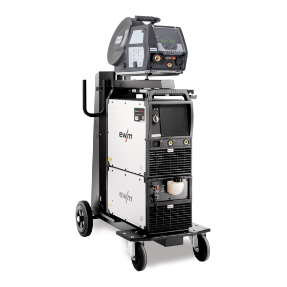
Page 16: Machine Description - Quick Overview
Machine description – quick overview Front view / rear view Machine description – quick overview Front view / rear view Figure 4-1 099-005589-EW501 9.02.2023... - Page 17 Machine description – quick overview Front view / rear view Item Symbol Description Carrying handle Ready for operation signal light Signal light on when the machine is switched on and ready for operation Main Switch Switching the machine on or off. Connection socket, “+”...
-
Page 18: Design And Function
Design and function Transport and installation Design and function WARNING Risk of injury from electrical voltage! Contact with live parts, e.g. power connections, can be fatal! • Observe the safety information on the first pages of the operating instructions! • Commissioning must be carried out by persons who are specifically trained in handling power sources! •... -
Page 19: Machine Cooling
Design and function Transport and installation 5.1.2 Machine cooling Insufficient ventilation results in a reduction in performance and equipment damage. • Observe the ambient conditions! • Keep the cooling air inlet and outlet clear! • Observe the minimum distance of 0.5 m from obstacles! 5.1.3 Workpiece lead, general CAUTION... -
Page 20: Connecting The Intermediate Hose Package To The Power Source
Design and function Transport and installation 5.1.5 Connecting the intermediate hose package to the power source 5.1.5.1 Intermediate hose package strain relief Missing or incorrectly fitted strain relief! Connection sockets or connection plugs on the machine, or the intermediate tube package, may be damaged if the strain relief is missing or incorrectly fitted. -
Page 21: Intermediate Hose Package Connection
Design and function Transport and installation 5.1.5.2 Intermediate hose package connection With this machine series, the earth cable on the intermediate hose package must not be connec- ted to the welding machine or wire feeder! Remove the earth cable or push back into the hose package! Some wire electrodes (e.g. -
Page 22: Welding Torch Holder
Design and function Transport and installation 5.1.6 Welding torch holder The item described in the following is part of the machine´s scope of delivery. Figure 5-4 Item Symbol Description Crossmember of the transport handle Torch holder Fixing screws (x 4) Fan-type lock washers •... -
Page 23: Mains Connection
Design and function Transport and installation 5.1.7 Mains connection DANGER Hazards caused by improper mains connection! An improper mains connection can cause injuries or damage property! • The connection (mains plug or cable), the repair or voltage adjustment of the device must be carried out by a qualified electrician in accordance with the respective local laws or nati- onal regulations! •... -
Page 24: Notes On The Installation Of Welding Current Leads
Design and function Transport and installation 5.1.8 Notes on the installation of welding current leads • Incorrectly installed welding current leads can cause faults in the arc (flickering). • Lay the workpiece lead and hose package of power sources without HF igniter (MIG/MAG) for as long and as close as possible in parallel. -
Page 25: Stray Welding Currents
Design and function Transport and installation 5.1.9 Stray welding currents WARNING Risk of injury due to stray welding currents! Stray welding currents can destroy protective earth conductors, damage machines and electronic devices and cause overheating of components, leading to fire. •... -
Page 26: Mig/Mag Welding
Design and function MIG/MAG welding MIG/MAG welding 5.2.1 Connection for workpiece lead Some wire electrodes (e.g. self-shielding cored wire) are welded using negative polarity. In this case, the welding current lead should be connected to the "-" welding current socket, and the workpiece lead should be connected to the "+"... -
Page 27: Mma Welding
Design and function MMA welding MMA welding CAUTION Risk of crushing and burns! When changing stick electrodes there is a risk of crushing and burns! • Wear appropriate and dry protective gloves. • Use an insulated pair of tongs to remove the used stick electrode or to move welded work- pieces. -
Page 28: Air Arc Gouging
Design and function Air arc gouging Air arc gouging During gouging, an arc burns between a carbon electrode and the workpiece, heating the workpiece until it is molten. At the same time, the molten metal is blown out with compressed air. Special electrode hol- ders with a compressed-air connection and carbon electrodes are required for gouging. -
Page 29: Maintenance, Care And Disposal
Maintenance, care and disposal General Maintenance, care and disposal General DANGER Risk of injury due to electrical voltage after switching off! Working on an open machine can lead to fatal injuries! Capacitors are loaded with electrical voltage during operation. Voltage remains present for up to four minutes after the mains plug is removed. -
Page 30: Maintenance Work, Intervals
A periodic test according to IEC 60974-4 "Periodic inspection and test" has to be carried out. In addition to the regulations on testing given here, the relevant local laws and regulations must also be observed. For more information refer to the "Warranty registration" brochure supplied and our information regarding warranty, maintenance and testing at www.ewm-group.com! 099-005589-EW501 9.02.2023... -
Page 31: Disposing Of Equipment
Information on returning used equipment or collections can be obtained from the respective municipal administration office. Devices can also be returned to EWM sales partners across Europe. Further information on the topic of the disposal of electrical and electronic equipment can be found on our website at: https://www.ewm-group.com/de/nachhaltigkeit.html. -
Page 32: Rectifying Faults
Rectifying faults Error messages (power source) Rectifying faults All products are subject to rigorous production checks and final checks. If, despite this, something fails to work at any time, please check the product using the following flowchart. If none of the fault rectification procedures described leads to the correct functioning of the product, please inform your authorised dea- ler. - Page 33 Rectifying faults Error messages (power source) Error 7: Low coolant level Category B Low flow rate. Fill with coolant. Check coolant flow - remove kinks in the hose package. Adjust the flow threshold Clean the cooler. ...
- Page 34 Rectifying faults Error messages (power source) Error 16: Pilot arc power source - collective error Category A The external emergency stop circuit has been interrupted. Check the emergency stop circuit and eliminate the cause of the error. The emergency stop circuit of the power source has been activated (internally configurable). Deactivate the emergency stop circuit.
- Page 35 Rectifying faults Error messages (power source) Error 20: Low coolant level Category B Low flow rate. Fill with coolant. Check coolant flow - remove kinks in the hose package. Adjust the flow threshold Clean the cooler. ...
- Page 36 Rectifying faults Error messages (power source) Error 32: Error I>0 Current recording is faulty. Request service. Error 33: Error UIST Voltage recording is faulty. Eliminate the short circuit in the welding circuit. Remove the external sensor voltage. ...
- Page 37 Rectifying faults Error messages (power source) Error 48: Ignition error Category B No ignition at process start (automated machines). Check the wire feeding Check the load cable connections in the welding circuit. Clean corroded surfaces on the workpiece before welding if necessary. ...
-
Page 38: Warnings
Rectifying faults Warnings Error 57: Slave tacho error Category B Fault in the wire feeder (slave drive). Check the connections (connectors, lines). Permanent overload of the wire drive (slave drive). Do not lay the liner in tight radii. ... - Page 39 Rectifying faults Warnings Warning Potential cause / remedy 2 Half-wave failures Check process parameters. 3 Torch cooling warning Check coolant level and top up if necessary. 4 Shielding gas Check shielding gas supply. 5 Coolant flow Check min. flow rate. 6 Wire reserve Only a small amount of wire is left on the spool.
-
Page 40: Checklist For Rectifying Faults
Rectifying faults Checklist for rectifying faults Warning Potential cause / remedy 34 JOB unknown JOB selection was not carried out because the JOB number is unknown. 35 Excess current on the wire feed Excess current detected on wire feed motor slave (push/push motor slave system or intermediate drive). -
Page 41: Vent Coolant Circuit
Rectifying faults Vent coolant circuit Wire feed problems Contact tip blocked Clean and, if necessary, replace. Setting the spool brake Check settings and correct if necessary Setting pressure units Check settings and correct if necessary ... -
Page 42: Technical Data
Technical data Taurus 355 Technical data Performance specifications and guarantee only in connection with original spare and replacement parts! Taurus 355 MIG/MAG Welding current (I 5 A to 350 A Welding voltage according to stan- 14,3 V to 31,5 V 20,2 V to 34,0 V dard (U Duty cycle DC at 40°... -
Page 43: Taurus 405
Technical data Taurus 405 Taurus 405 MIG/MAG Welding current (I 5 A to 400 A Welding voltage according to stan- 14,3 V to 34 V 20,2 V to 36,0 V dard (U Duty cycle DC at 40° C 400 A (100 %) Open circuit voltage (U 79 V Mains voltage (Tolerance) -
Page 44: Taurus 505
Technical data Taurus 505 Taurus 505 MIG/MAG Welding current (I 5 A to 500 A Welding voltage according to stan- 14,3 V to 39,0 V 20,2 V to 40,0 V dard (U Duty cycle DC at 40° C 500 A (60 %) / 430 A (100 %) Open circuit voltage (U 79 V Mains voltage (Tolerance) -
Page 45: Accessories
Accessories System components Accessories Performance-dependent accessories like torches, workpiece leads, electrode holders or intermediate hose packages are available from your authorised dealer. System components Type Designation Item no. Drive 4X Steel puls S Wire feeder, water cooled, Euro torch connector 090-005593-00502 Drive 4X Steel Synergic S Wire feeder, water cooled, Euro torch connector... -
Page 46: Appendix
Appendix Searching for a dealer Appendix 10.1 Searching for a dealer Sales & service partners www.ewm-group.com/en/specialist-dealers "More than 400 EWM sales partners worldwide" 099-005589-EW501 9.02.2023...
Need help?
Do you have a question about the Taurus 355-505 Basic S and is the answer not in the manual?
Questions and answers