Table of Contents
Advertisement
Quick Links
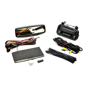
Rear Vision System – Tailgate Handle Camera Mirror Display
2004-2014 Ford F-150 and 2008-2015 Ford Super Duty
(Kit part numbers 9002-9521)
Kit Contents:
Mirror
Tailgate Handle with camera and harness
Interior (shorter) Harness
Chassis (longer) Harness
2 Foam pieces (if needed and optional)
1 bag containing:
25 Wire Ties (short)
7 pairs of T-taps (optional)
(Splice, solder & heat shrink
recommended.)
Z-Tech (in a white bottle)
1 bag containing:
2 Templates (along with these instructions)
2 Wire Ties (long and optional)
NOTE: We strive to provide accurate and up-to-date installation instructions. For the latest full
color instructions, as well as an installation video, please visit www.brandmotion.com
Preparation
Ensure all lamps and accessories are OFF.
•
Ensure the ignition switch is in the OFF position.
•
Loosen the negative battery cable bolt. Remove negative battery cable from terminal and position away
•
from battery.
Wait one (1) minute prior to working on the vehicle to assure airbag system has been disabled for your
•
safety.
Before beginning, determine how the vehicle is equipped and check appropriate boxes:
Start vehicle and note location of compass display. Unplug mirror connector from back of mirror.
• If compass display on the dash shows (- -) the compass module must be relocated (refer to Section 6).
Determine whether the vehicle has an opening in the center of pickup bed close to opposite of the opening in
the bottom of the tailgate.
□ Yes, skip Section 1.
□ No, tailgate must be removed to drill an opening for the camera harness
(refer to Section 1).
□ Vehicle does NOT have an auto dimming inside mirror (refer to Section 7).
Determine the connector style used on the existing inside rearview mirror:
7-pin or 16-pin. For past models additional information, please see Section 10B (reference).
□ Check kit contents are complete against the list above.
9521 Instructions 2-12-15.doc
INSTALLATION INSTRUCTIONS
PRE-INSTALLATION VEHICLE CHECKLIST
Tools Required:
T20 and T30 Torx Drivers
8mm and 10mm Sockets
Flat Blade Screwdriver
Phillips Screwdriver
Plastic Trim Removal tool
Drill Bit
1 inch Center Hole Saw
Soldering Iron
Small brush
Round file (if needed)
Mirror removal tool # OTC8200
(Required for non-screw type mirrors)
Deburring Tool
Electrical Tape or Heat Shrink
1 of 35
Advertisement
Table of Contents

Subscribe to Our Youtube Channel
Related Manuals for BrandMotion 9002-9521


Summary of Contents for BrandMotion 9002-9521
-
Page 1: Installation Instructions
2 Wire Ties (long and optional) Electrical Tape or Heat Shrink NOTE: We strive to provide accurate and up-to-date installation instructions. For the latest full color instructions, as well as an installation video, please visit www.brandmotion.com Preparation Ensure all lamps and accessories are OFF. -
Page 2: Table Of Contents
INSTALLATION INSTRUCTIONS TABLE OF CONTENTS Pages Section 1: Cut Pickup Bed Opening (if required) Section 2: Install Camera Section 3: Modify Rain Sensor (if equipped) Section 4: Remove Mirror Section 5: Install Interior Harness Section 6: Wire Interior Harness 6A: Remove compass circuit board (if required) 6B: Wiring for vehicles with 7-pin mirror connector 6C: Wiring for vehicles with 16-pin mirror connector... -
Page 3: Section 1: Cut Pickup Bed Opening
INSTALLATION INSTRUCTIONS Section 1: Cut Pickup Bed Opening Follow Steps 1 through 4 only if the vehicle does not have an opening in the bed above the license plate per Figure 1 Figure 1 3. Center punch the mark and drill a pilot hole. Next, cut a 1/2 inch opening with a hole saw (Figure 3). -
Page 4: Section 2: Install Camera
INSTALLATION INSTRUCTIONS Section 2: Install Camera 5. Remove tailgate handle by loosening two nuts with a 10mm socket (Figure 5). Figure 5 Figure 7 6. Remove lock cylinder from tailgate handle by pulling out wire spring clip (Figure 6). Figure 6 9. -
Page 5: Section 3: Modify Rain Sensor
INSTALLATION INSTRUCTIONS Section 3: Modify Rain Sensor Section 4: Remove Mirror (If equipped 12. If you did not already do so previously, start the vehicle and note location of compass display. Unplug Follow Steps 10 and 12 on this page the mirror connector from mirror (Figure 12). -
Page 6: Section 5: Install Interior Harness
INSTALLATION INSTRUCTIONS Section 5: Install Interior Harness 15. Remove driver side dash panel end cap by pulling 18. Remove roof console with hands to remove the clips away weather-stripping and pull end panel to from the sheet metal. Then remove both connectors release clips from the dash panel (Figure 14). - Page 7 INSTALLATION INSTRUCTIONS Section 5: Install Interior Harness continued 21. Route the supplied interior harness through the dash (Figure 20). Figure 20 9521 Instructions 2-12-15.doc 7 of 35...
- Page 8 INSTALLATION INSTRUCTIONS Section 6A: Remove the Compass Circuit Board (if required) Follow the steps in Section 6A only if your compass displayed (- -) when the mirror connector was unplugged in Section 4. 22. Pry mirror apart with a screwdriver (Figure 21). 24.
-
Page 9: Wiring For Vehicles With 7-Pin Mirror Connector
INSTALLATION INSTRUCTIONS Section 6B: Wiring vehicles with 7-pin mirror connector 26. On the supplied interior harness, locate the seven 29. Consulting the Connector C911 pinout diagram loose wires near the black 16-pin connector (Figure below, splice the five pink, green, black, red, and yellow wires to the vehicle mirror harness connector Figure 24 according to Diagram A1. -
Page 10: Wiring For Vehicles With 16-Pin Mirror Connector
INSTALLATION INSTRUCTIONS Section 6C: Wiring for vehicles with 16-pin mirror connector 31. On the supplied interior harness, near the black 16 pin connector, locate the seven loose wires. (Figure 32. Isolate the pink wire with electrical tape as it will not be used. -
Page 11: Relocate Compass Circuit Board (If Required)
INSTALLATION INSTRUCTIONS Section 6D: Relocate the Compass Circuit Board (if required) Follow the steps in Section 6D only if your compass displayed (- -) when the mirror connector was unplugged in Section 4. 38. Solder all connections and cover with heat shrink Figure 28 tubing or electrical tape. -
Page 12: Dimming (If Required)
INSTALLATION INSTRUCTIONS Section 7: Inside Rear View Mirrors without Auto Dimming (if required) Follow the steps in Section 7 only if the vehicle does not have an auto dimming inside rear view mirror. 44. Remove the passenger side door sill plate with a Figure 33 trim tool and remove passenger side kick panel with hands, just disengaging the two clips from the sheet... - Page 13 INSTALLATION INSTRUCTIONS Section 7: Inside Rear View Mirrors without Auto Dimming continued (if required) Non Auto Dimming Pinouts Diagram A3 Supplied Chassis Harness Ignition & Reverse Locations Interior Harness Dia. Model Year(s) Function Connector Location Color Color Page Right Ignition C2280B Kick Violet/Green...
- Page 14 INSTALLATION INSTRUCTIONS Section 7: Inside Rear View Mirrors without Auto Dimming continued (if required) INSIDE REAR VIEW MIRROR WITHOUT AUTO DIMMING DIAGRAM A4 Ignition Connector C2280B – 2012 late production F150 9521 Instructions 2-12-15.doc 14 of 35...
- Page 15 INSTALLATION INSTRUCTIONS Section 7: Inside Rear View Mirrors without Auto Dimming continued (if required) INSIDE REAR VIEW MIRROR WITHOUT AUTO DIMMING DIAGRAM A5 Reverse Connector C2280D – 2012 late production F150 and Super Duty 9521 Instructions 2-12-15.doc 15 of 35...
- Page 16 INSTALLATION INSTRUCTIONS Section 7: Inside Rear View Mirrors without Auto Dimming continued (if required) INSIDE REAR VIEW MIRROR WITHOUT AUTO DIMMING DIAGRAM A6 Ignition Connector C2280B – 2012 late production Super Duty 9521 Instructions 2-12-15.doc 16 of 35...
-
Page 17: Section 8: Install Supplied Mirror
INSTALLATION INSTRUCTIONS Section 8: Supplied Mirror Installation 50. Plug the 16-pin connector from the supplied interior harness into the supplied mirror (Figure 35). Figure 35 51. Install the supplied mirror on the mounting button and slide it downwards. Secure by tightening the T20 Torx screw to 1.8 Nm (16 lb-in.), while not exceeding 2.2 Nm (19.5 lb-in.). -
Page 18: Section 9: Install Chassis Harness
INSTALLATION INSTRUCTIONS Section 9: Chassis Harness Installation 53. Remove the driver side sill plate with a trim tool Figure 38 (Figure 36). Figure 36 56. Secure Super Duty template number 1008-9100-03 (Figure 39) or secure F150 template number 1008- 9100-04 over opening in front of driver’s seat (Figure 40). - Page 19 INSTALLATION INSTRUCTIONS Section 9: Chassis Harness Installation continued 57. Center punch and drill a pilot hole. Figure 43 58. Drill a 1/2 inch hole, clean the hole with a deburring tool (Figure 41). Figure 41 61. Route the supplied chassis harness toward the supplied interior harness and connect the RCA connectors together.
- Page 20 INSTALLATION INSTRUCTIONS Section 9: Chassis Harness Installation continued 62. Route the exterior portion of the supplied chassis Figure 47 harness along existing vehicle chassis harness and over fuel tank. Using supplied tie wraps, secure the harness to existing wiring at 2 inch intervals (Figures 45 and 46).
- Page 21 INSTALLATION INSTRUCTIONS 65. Move heat shrink over the connection between the chassis harness and camera (Figure 49). Figure 49 66. Heat and seal the connection between the chassis harness and camera (Figure 50). Figure 50 67. Start vehicle with foot on brake and shift into reverse to check camera operation.
-
Page 22: Section 10: Reference 10A: Supplied Harness Pinouts
NOTE: Not Used Pin cavities are numbered on the back Ignition (Run Only Line) side of the 16-pin connector. Additionally, Brandmotion identifies Not Used Pin 1 with a white mark. Not Used Dual Outside Drive EC (-) 9521 Instructions 2-12-15.doc... - Page 23 INSTALLATION INSTRUCTIONS Section 10B: Reference – Previous Model Year Mirror Connector Pinouts Supplied Microphone Interior Supplied Harness Color Harness Color 1 Blue (+) 1 Red 2 Green 3 Black 3 Black 6 Yellow 9 Pink 10 Yellow 14 Black Supplied Interior Harness Color 1 Red...
-
Page 24: Previous Model Year Mirror Connector Pinouts
INSTALLATION INSTRUCTIONS Section 10B: Reference – Previous Model Year Mirror Connector Pinouts continued 2004-2007 F150 Pinout 9521 Instructions 2-12-15.doc 24 of 35... -
Page 25: Previous Model Year Ignition & Reverse Locations
INSTALLATION INSTRUCTIONS Section 10C: Reference – Previous Model Year Ignition & Reverse Locations Supplied Interior Harness Dia. Model Year Function Connector Page Location Color Color White / Ignition C270J Right Kick L. Blue F150 2004 Black / Reverse C270E Right Kick Green Pink White /... - Page 26 INSTALLATION INSTRUCTIONS Section 10C: Reference – Previous Model Year Ignition & Reverse Locations continued Ignition Connector C270J – 2004 – 2008 F150 9521 Instructions 2-12-15.doc 26 of 35...
- Page 27 INSTALLATION INSTRUCTIONS Section 10C: Reference – Previous Model Year Ignition & Reverse Locations continued Reverse Connector C270E – 2004 F150 9521 Instructions 2-12-15.doc 27 of 35...
- Page 28 INSTALLATION INSTRUCTIONS Section 10C: Reference – Previous Model Year Ignition & Reverse Locations continued Reverse Connector C270B – 2005-2008 F150 9521 Instructions 2-12-15.doc 28 of 35...
- Page 29 INSTALLATION INSTRUCTIONS Section 10C: Reference – Previous Model Year Ignition & Reverse Locations continued Ignition Connector C2280D – 2009-2012 (early production) F150 9521 Instructions 2-12-15.doc 29 of 35...
- Page 30 INSTALLATION INSTRUCTIONS Section 10C: Reference – Previous Model Year Ignition & Reverse Locations continued Reverse Connector C215 – 2009-2012 (early production) F150 9521 Instructions 2-12-15.doc 30 of 35...
- Page 31 INSTALLATION INSTRUCTIONS Section 10C: Reference – Previous Model Year Ignition & Reverse Locations continued Ignition and Reverse Connector C264 – 2008 Super Duty 9521 Instructions 2-12-15.doc 31 of 35...
- Page 32 INSTALLATION INSTRUCTIONS Section 10C: Reference – Previous Model Year Ignition & Reverse Locations continued Ignition and Reverse Connector C264 – 2009-2012 (early production) Super Duty 9521 Instructions 2-12-15.doc 32 of 35...
-
Page 33: Relocating The Compass Circuit Board For Vehicles With External Compass Module
INSTALLATION INSTRUCTIONS Section 10D: Reference – Relocating the Compass Circuit Board for vehicles with External Compass Module (if required) 69. Remove the separate compass module from the 71. Pry the compass module apart with a screwdriver existing interior mirror by sliding it downwards (Figure 51). - Page 34 INSTALLATION INSTRUCTIONS Section 10D: Reference – Relocating the Compass Circuit Board for vehicles with External Compass Module continued (if required) 73. Wrap the circuit board in the supplied foam and cut Figure 55 an opening for connector terminal (Figure 53). Figure 53 74.
-
Page 35: Vehicles With Sync Microphone In Mirror ( If Equipped)
INSTALLATION INSTRUCTIONS Section 10E: Reference – Vehicles with Sync Microphone in Mirror Follow the steps on this page only for auto dimming inside rear view mirror with built in Sync microphone. 76. Splice the supplied interior harness to the vehicle mirror harness by following the next ten steps and Diagram A7. NOTE: Isolate the black, green and pink wires at the white 6 pin connector end of the supplied interior harness with electrical tape as they will not be used.
Need help?
Do you have a question about the 9002-9521 and is the answer not in the manual?
Questions and answers