Advertisement
Jeep Wrangler Adjustable Rear Vision
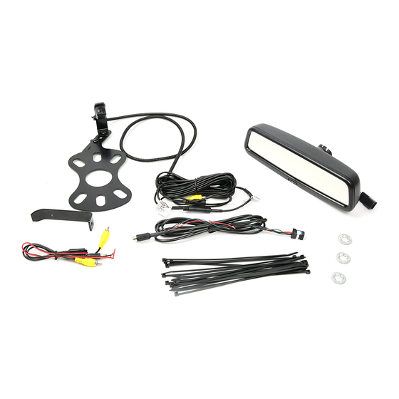
Items Included in the Kit
Camera
Chassis Harness
Zip lock bag with 15 Wire Ties & 3 Push Nuts
These Instructions
Display Mirror with Harness
Camera Extension Bracket
Please read so you do not V OID the warranty:
9002-8846 Instructions 9-17-19
2007 – Current (Kit # 9002-8846)
Page 1 of 8
S ystem with Mirror Display
Required Tools & Supplies
T15 & T20 Torx Bits
7mm & 10mm Sockets
Phillips Screwdriver
Plastic Trim Removal Tool
Soldering Iron, Solder, & Heat Shrink Tubing
(RECOMMENDED) or T-taps as an alternate splicing
method
Electrical Tape
DM
Advertisement
Table of Contents

Subscribe to Our Youtube Channel
Related Manuals for BrandMotion 9002-8846


Summary of Contents for BrandMotion 9002-8846
- Page 1 INSTALLATION INSTRUCTIONS Jeep Wrangler Adjustable Rear Vision S ystem with Mirror Display 2007 – Current (Kit # 9002-8846) Items Included in the Kit Camera Required Tools & Supplies Chassis Harness T15 & T20 Torx Bits Zip lock bag with 15 Wire Ties & 3 Push Nuts 7mm &...
- Page 2 Temporarily replace spare tire to check wheel clearance to Camera. Adjust camera head to fit your specific wheel. Bracket is shipped in factory wheel configuration Note: Short Bracket has been designed for Factory offset 9002-8846 Instructions 9-17-19 Page 2 of 8...
- Page 3 9. Use supplied Wire Ties to secure Chassis Harness to fabric factory wire cover. CAUTION: Leave enough slack to allow the gate to open fully. 10. Use a T20 Torx bit to remove the subwoofer box. (If 9002-8846 Instructions 9-17-19 Page 3 of 8...
- Page 4 10mm bolt, and remove bolt. Remove 7mm bolt. 13. Pull out subwoofer box slightly to gain access to run Chassis Harness along existing harness 14. Pull back the carpet and continue running Chassis 9002-8846 Instructions 9-17-19 Page 4 of 8...
- Page 5 22. Remove (2) 7mm bolts on both sides of the steering Disconnect harness from window switches. column. 23. Remove center stack/cluster surround. 20. Remove 7mm bolt. 24. Remove glove box for access and run Chassis Harness toward the center of the dash. 9002-8846 Instructions 9-17-19 Page 5 of 8...
- Page 6 Begin running 10-pin mirror connector end of Mirror Harness to mirror by first removing IP access panel. Use a T15 Torx bit to remove factory mirror and slide the mirror upward off the mounting tab. 9002-8846 Instructions 9-17-19 Page 6 of 8...
- Page 7 16 Pin Position 9 - Reverse White/Gray to Green Wire Remove lower A-pillar cover (no tools required). 16 Pin Position 13 - 12v Ignition Pink/Yellow to Red Wire 16 Pin Position 8 – Ground Black to Black Wire 9002-8846 Instructions 9-17-19 Page 7 of 8...
- Page 8 If all of the connections are correct you will see the camera image displayed on the display mirror 14. Reassemble vehicle. Follow your disassembly steps in reverse order, taking care not to bind the harness wiring when reinstalling the trim. 9002-8846 Instructions 9-17-19 Page 8 of 8...
Need help?
Do you have a question about the 9002-8846 and is the answer not in the manual?
Questions and answers