Advertisement
Please read thoroughly before starting installation and check that kit contents are complete.
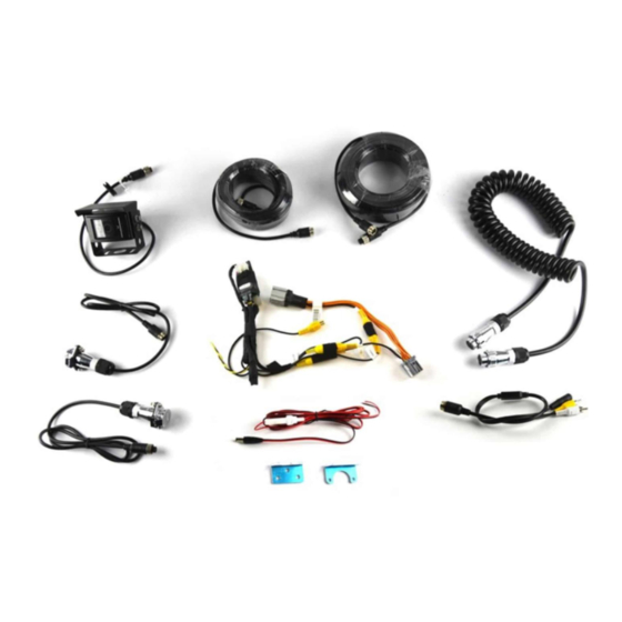
Items Included in the Kit:
10m 4pin Connector Cable
20m 4pin Connector Cable
4pin-to-RCA connector
Camera Power Harness
2 Connector Mounting Brackets
1 IR Camera
2 Vehicle Mounted Connectors
1 4pin Coiled Cable
1 GM Display Screen T-Harness
Safety Precautions:
Work in well ventilated area that is clear of obstructions.
●
Secure vehicle with tire chucks in both front and rear of tires.
●
Turn vehicle accessories OFF and ensure ignition key is in OFF position.
●
Wear safety goggles and snug fitting clothes.
●
Use tools only for their intended purpose and which are in good repair.
●
Only perform this task if confidence, skill, and physical ability permit.
●
NOTE: We strive to provide accurate and up-to-date installation instructions. For the latest full color
instructions, as well as an installation video, please visit
9002-7804V2 Instructions 7/8/20
Trailer Rear Vision Kit for
GM 8" or 4" Display
(Kit # 9002-7804V2)
Tools & Supplies Needed:
Electrical tape
Zip ties
1" Hole Saw
3/16" Drill Bit
Digital Volt Meter / BCM safe test light
Screwdriver
Socket set
T-15 Torx bit
Wrench
Page 1 of 8
INSTALLATION INSTRUCTIONS
w ww.brandmotion.com
AR
Advertisement
Table of Contents

Related Manuals for BrandMotion 9002-7804V2


Summary of Contents for BrandMotion 9002-7804V2
- Page 1 INSTALLATION INSTRUCTIONS Trailer Rear Vision Kit for GM 8" or 4” Display (Kit # 9002-7804V2) Please read thoroughly before starting installation and check that kit contents are complete. Items Included in the Kit: Tools & Supplies Needed: 10m 4pin Connector Cable...
- Page 2 2. Zip tie the cable up along the frame rails. Some trailers have holes cut into the frame rail for factory wiring, try to follow these. 3. Make sure to use the male-ended plug for the trailer. (If the wrong one is used the plug will not be correct for the camera.) 9002-7804V2 Instructions 7/8/20 Page 2 of 8...
- Page 3 INSTALLATION INSTRUCTIONS 4. Connect the 4-pin harness(s) to the trailer side plug. 9002-7804V2 Instructions 7/8/20 Page 3 of 8...
- Page 4 6. Attach the plug to the bracket by removing the 2 nuts and washers. Then attach the plug to the front of the bracket and secure with the original washers and nuts. 9002-7804V2 Instructions 7/8/20 Page 4 of 8...
- Page 5 4. There is an included aluminum bracket if you do not wish to drill into the exterior of the truck. This is the same style 90º bracket that is used for the trailer plug. 9002-7804V2 Instructions 7/8/20 Page 5 of 8...
- Page 6 Once you have removed the back glove box panel, you should be able to spot the HMI. You will be looking at the connector end, and there are 6 different connectors plugged into it. 9002-7804V2 Instructions 7/8/20 Page 6 of 8...
- Page 7 12v+ ignition and the black wire to ground. For Use: 1. Connect coiled 4-pin connector cable for trailer to truck 2. Shift truck into reverse to show trailer camera image on factory display. 9002-7804V2 Instructions 7/8/20 Page 7 of 8...
- Page 8 INSTALLATION INSTRUCTIONS 9002-7804V2 Instructions 7/8/20 Page 8 of 8...
Need help?
Do you have a question about the 9002-7804V2 and is the answer not in the manual?
Questions and answers