Table of Contents
Advertisement
Quick Links
Please read thoroughly before starting installation and
Please read thoroughly before starting installation and check that kit contents are complete.
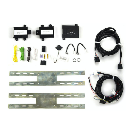
Items Included in the Kit:
1 Bumper/Radar Harness
1 Interior/Chassis Harness
22 ga. White, Brown, and Yellow Wire (4
feet)
22 ga. Light Green and Red Wire (10 feet)
HMI Display Set (includes left and right side
& 2 retaining clips)
Piezo Buzzer
Integration CAN ECU
BSD Radar Sensors (24 GHz left and right)
8 1/8-inch Black Heat Shrink
Fuse Holder and 3 amp fuse
12 Zip Ties
1 Z-Tech rust inhibitor
2 Universal Mounting brackets
6 ¾-inch stainless steel Phillips screws
6 Nyloc stainless steel nuts
12 5mm stainless steel washers
8 self-tapping ¼-inch drive screws
Protractor
RDBS-1500 Instructions 7/26/18
Universal Radar Blind Spot System
(Part # RDBS-1500)
check that kit contents are complete.
Page 1 of 15
Tools & Supplies Needed:
Electrical tape
Zip ties
1" Hole Saw
3/16" Drill Bit
Digital Volt Meter / BCM safe test
light
Screwdriver
Socket set
Wrench
KB
Advertisement
Table of Contents

Related Manuals for BrandMotion RDBS-1500


Summary of Contents for BrandMotion RDBS-1500
-
Page 1: Installation Instructions
INSTALLATION INSTRUCTIONS Universal Radar Blind Spot System (Part # RDBS-1500) Please read thoroughly before starting installation and check that kit contents are complete. Please read thoroughly before starting installation and check that kit contents are complete. Items Included in the Kit: Tools &... -
Page 2: Safety Precautions
1. When installing the radar modules, use the recommended smartphone app (or the included protractor) to check the angle for the radar modules. Brandmotion recommends 4 5 degrees from the back of the vehicle as optimal, but can be between 42 to 48 degrees. The elevation angle (or “pitch”) from top to bottom should be between ... - Page 3 BROWN wire connects to the vehicle’s PARKING LIGHTS positive wire. e. RED wire connects to vehicle IGNITION. f. BLACK plastic-coated wire connects to a good, clean GROUND in the vehicle. 5. Pinouts for the ECU connector: RDBS-1500 Instructions 7/26/18 Page 3 of 15...
- Page 4 4. Attach the BLUE CAN HI wire from the ECU to pin location 6 on the vehicle’s OBDII connector. 5. Attach the BROWN CAN LOW wire from the ECU to pin location 14 on the vehicle's OBDII connector RDBS-1500 Instructions 7/26/18 Page 4 of 15...
- Page 5 INSTALLATION INSTRUCTIONS PREPARING BRACKET Radar module mounted on studs: Use a washer in between the nut and the radar and in between the screw head and the bracket RDBS-1500 Instructions 7/26/18 Page 5 of 15...
- Page 6 INSTALLATION INSTRUCTIONS Using protractor to measure mounting angles: BRACKET MOUNTING EXAMPLES: RDBS-1500 Instructions 7/26/18 Page 6 of 15...
- Page 7 INSTALLATION INSTRUCTIONS RDBS-1500 Instructions 7/26/18 Page 7 of 15...
- Page 8 INSTALLATION INSTRUCTIONS HMI MOUNTING EXAMPLE: RDBS-1500 Instructions 7/26/18 Page 8 of 15...
- Page 9 INSTALLATION INSTRUCTIONS RDBS-1500 Instructions 7/26/18 Page 9 of 15...
- Page 10 INSTALLATION INSTRUCTIONS RDBS-1500 Instructions 7/26/18 Page 10 of 15...
- Page 11 INSTALLATION INSTRUCTIONS RDBS-1500 Instructions 7/26/18 Page 11 of 15...
- Page 12 INSTALLATION INSTRUCTIONS RDBS-1500 Instructions 7/26/18 Page 12 of 15...
- Page 13 INSTALLATION INSTRUCTIONS RDBS-1500 Instructions 7/26/18 Page 13 of 15...
- Page 14 INSTALLATION INSTRUCTIONS RDBS-1500 Instructions 7/26/18 Page 14 of 15...
- Page 15 INSTALLATION INSTRUCTIONS RDBS-1500 Instructions 7/26/18 Page 15 of 15...
Need help?
Do you have a question about the RDBS-1500 and is the answer not in the manual?
Questions and answers