Advertisement
Quick Links
Jeep Wrangler Adjustable Rear Vision
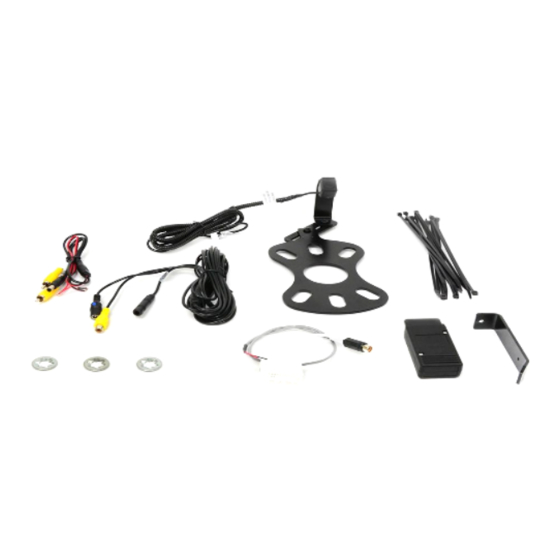
Items Included in the Kit
Camera
Chassis Harness
Power Harness
22--pin white connector w/ video RCA (for factory
display radio)
Program Module
Zip lock bag with 15 Wire Ties & 3 Push Nuts
Camera Extension Bracket
These Instructions
Please read so you do not V OID the
If the camera harness is run through the center on the camera bracket, it
will cut the camera harness. This will void the warranty on the camera.
9002-8847 Instructions 6-10-19.docx
2007 – 2018 JK (Kit # 9002-8847)
warranty:
Page 1 of
INSTALLATION INSTRUCTIONS
S ystem for Factory Display Radios
Required Tools & Supplies
T15 & T20 Torx Bits
7mm & 10mm Sockets
Phillips Screwdriver
3/8" Wrench or Socket Drive
Plastic Trim Removal Tool
Soldering Iron, Solder, & Heat Shrink Tubing
(RECOMMENDED) or T-taps as an alternate
splicing method
Electrical Tape
7
KB
,
Advertisement

Subscribe to Our Youtube Channel
Related Manuals for BrandMotion 9002-8847


Summary of Contents for BrandMotion 9002-8847
- Page 1 INSTALLATION INSTRUCTIONS Jeep Wrangler Adjustable Rear Vision S ystem for Factory Display Radios 2007 – 2018 JK (Kit # 9002-8847) Items Included in the Kit Required Tools & Supplies Camera T15 & T20 Torx Bits Chassis Harness 7mm & 10mm Sockets...
-
Page 2: Install Camera
INSTALLATION INSTRUCTIONS NOTE: We strive to provide accurate and up-to-date installation instructions. For the latest full color instructions, as well as an installation video, please visit www.brandmotion.com Install Camera Step 1: Loosen lug nuts to remove spare tire. Adjustment Bracket for Camera Clearance using Phillips Screwdriver and 3/8”... -
Page 3: Install Chassis Harness
Step 10: Use supplied Wire Ties to secure Chassis Harness to existing harness. Step 7: Using a plastic trim removal tool, remove interior panels on inside of rear gate. 7 9002-8847 Instructions 6-10-19.docx Page 3 of... - Page 4 Step 17: Run Chassis Harness under B-pillar cover to passenger door sill. Use a plastic trim removal tool to remove the (2) plastic push pins and remove passenger sill plate/kick panel. 7 9002-8847 Instructions 6-10-19.docx Page 4 of...
- Page 5 Step 18: R emove rubber bin insert from top of dash. Step 22: Remove 7mm bolt. Step 19: R emove 7mm bolt . Step 23: Remove driver knee bolster cover. Step 20: Using a plastic trim removal tool, remove window switch panel. 7 9002-8847 Instructions 6-10-19.docx Page 5 of...
- Page 6 Step 26: R emove glove box for access and run Mirror Harness toward center of dash. Step 30: Insert the white 22-pin connector into the back of radio. Step 27: U sing a plastic trim removal tool, remove HVAC panel. 7 9002-8847 Instructions 6-10-19.docx Page 6 of...
- Page 7 Default setting is mirror image display for rearward facing camera (rear view) installation. To change to non mirror image for forward facing camera (front view) connect the two white wires near the end of the camera harness. 7 9002-8847 Instructions 6-10-19.docx Page 7 of...
Need help?
Do you have a question about the 9002-8847 and is the answer not in the manual?
Questions and answers