Advertisement
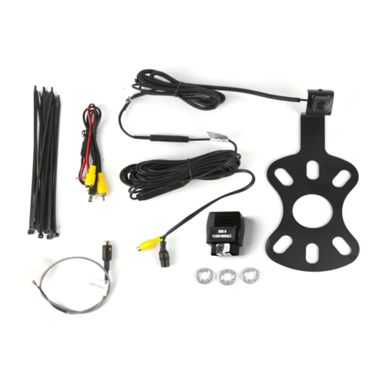
Items Included in the Kit
Camera
Chassis Harness
Zip lock bag with 15 Wire Ties & 3 Push Nuts
These Instructions
22--pin white connector w/ video RCA
OBDII Flash module
9002-8817 Instructions
Jeep Wrangler Rear Vision Camera Kit
2007 – Current (Kit # 9002-8817)
Required Tools & Supplies
T15 & T20 Torx Bits
7mm & 10mm Sockets
Phillips Screwdriver
Plastic Trim Removal Tool
Soldering Iron, Solder, & Heat Shrink Tubing
(RECOMMENDED) or T-taps as an alternate
splicing method
Electrical Tape
Page 1 of 7
Advertisement
Table of Contents

Related Manuals for BrandMotion 9002-8817


Summary of Contents for BrandMotion 9002-8817
- Page 1 INSTALLATION INSTRUCTIONS Jeep Wrangler Rear Vision Camera Kit 2007 – Current (Kit # 9002-8817) Items Included in the Kit Required Tools & Supplies Camera T15 & T20 Torx Bits Chassis Harness 7mm & 10mm Sockets Zip lock bag with 15 Wire Ties & 3 Push Nuts...
- Page 2 Step 2: Slide Camera on studs placing harness end inside of tire carrier. Do not run harness through the camera bracket opening . Step 3: Temporarily replace spare tire to check wheel clearance to Camera. 9002-8817 Instructions Page 2 of 7...
-
Page 3: Installation Instructions
Step 9: Use supplied Wire Ties to secure Chassis Harness to fabric factory wire cover. CAUTION: Leave enough slack to allow the gate to open fully. 9002-8817 Instructions Page 3 of 7... - Page 4 Step 14: Pull back the carpet and continue running Chassis Harness forward. Step 17: In the factory wire harness located in the passenger's footwell, locate the White/Gray Reverse signal wire and splice Green Reverse wire from supplied 9002-8817 Instructions Page 4 of 7...
- Page 5 Step 20: Using a plastic trim removal tool, remove the window switch panel. Step 24: Remove (2) 7mm bolts on both sides of the steering column. Step 21: D isconnect harness from window switches. 9002-8817 Instructions Page 5 of 7...
- Page 6 Step 29: Splice Red power wire and the green trigger wire from the chassis harness to Blue/Red wire on back of power point/cigarette lighter. RECOMMENDED: Use solder and cover with heat shrink tubing or use T-taps as an alternate connection method. 9002-8817 Instructions Page 6 of 7...
- Page 7 If all the connections are correct, you will see the camera image displayed on the factory display screen. T o enable or disable the camera input, select from among rear vision options in radio settings. 9002-8817 Instructions Page 7 of 7...
Need help?
Do you have a question about the 9002-8817 and is the answer not in the manual?
Questions and answers