
Related Manuals for Infortrend EonStor S12F-R1432


Summary of Contents for Infortrend EonStor S12F-R1432
- Page 1 ® EonStor S12F-R1432 S12F-G1433 4G FC to SAS/SATA-II RAID Subsystem Installation and Hardware Reference Manual Rev. 1.1 (May, 2008)
-
Page 2: Contact Information
EonStor S12F-R1432/G1433 Installation and Hardware Reference Manual Contact Information Asia Pacific Americas (International Headquarters) Infortrend Corporation 2200 Zanker Road, Unit D, Infortrend Technology, Inc. San Jose, CA. 95131 8F, No. 102 Chung-Shan Rd., Sec. 3 Chung-Ho City, Taipei Hsien, Taiwan... -
Page 3: Disclaimer
Infortrend Technology, Inc. Disclaimer Infortrend Technology makes no representations or warranties with respect to the contents hereof and specifically disclaims any implied warranties of merchantability or fitness for any particular purpose. -
Page 4: Fcc Class A Radio Frequency Interference Statement
EonStor S12F-R1432/G1433 Installation and Hardware Reference Manual Warnings and Certifications Restricted Access Location: This equipment is intended to be installed in a RESTRICTED ACCESS LOCATION only. Electric Shock Warning! To Prevent Electric Shock: Access to this equipment is granted only to trained operators and... - Page 5 EonStor S12F-R1432/G1433 Installation and Hardware Reference Manual interference, and 2) this device must accept any interference received, including interference that may cause undesired operation. Warning! A shielded power cord is required in order to meet FCC emission limits and also to prevent interference with nearby radio and television reception.
- Page 6 EonStor S12F-R1432/G1433 Installation and Hardware Reference Manual This device is in conformity with UL standards for safety. This device is in conformity with Russia GOST-R standards for safety. Инструкция по безопасности Модель: FC to SAS/SATA 2U/12Bay RAID Subsystem, Models ESS12F- R1432xxxxxx, ESS12F-G1433xxxx, where “x”...
- Page 7 European directive, RoHS (2002/95/EC), on or before the specific dates set forth in those applicable laws and regulations. Infortrend is applying its own internal efforts and expertise and is working closely with customers and suppliers to achieve compliance while maintaining an uninterrupted supply of quality products.
-
Page 8: Table Of Contents
EonStor S12F-R1432/G1433 Installation and Hardware Reference Manual Table of Contents ....................ONTACT NFORMATION 2008 ....................... OPYRIGHT Disclaimer………………………………………………………………………………………….iii Trademarks ……………………………………………………………………………………….iii ....................AFETY RECAUTIONS Precautions and Instructions..................... xii ESD Precautions......................xiii ....................BOUT ANUAL XIII ....................EVISION ISTORY ? ................HO SHOULD READ THIS MANUAL Related Documentation .................... - Page 9 EonStor S12F-R1432/G1433 Installation and Hardware Reference Manual 2.7.3 Drive Installation with MUX Kit..............2-17 ................2-18 RIVE NSTALLATION BBU I ..................2-20 NSTALLATION 2.9.1 BBU Warnings and Precautions ............... 2-20 2.9.2 Installation Procedure ................2-21 CHAPTER 3 SUBSYSTEM CONNECTION FC H ............
- Page 10 EonStor S12F-R1432/G1433 Installation and Hardware Reference Manual ............5-16 EPLACING A AULTY OOLING ODULE 5.6.1 Notes on Cooling Module Maintenance ............ 5-16 5.6.2 Cooling Module Replacement Procedure ..........5-17 5.6.2.1 Replacing a Cooling Module on S12F-R1432………………………………5-17 5.6.2.2 Replacing a Cooling Module on S12F-G1433...........5-19 ..............
-
Page 11: Safety Precautions
EonStor S12F-R1432/G1433 Installation and Hardware Reference Manual Safety Precautions Precautions and Instructions • Provide a soft, clean surface to place your subsystem on before working on it. Servicing on a rough surface may damage the exterior of the chassis. •... -
Page 12: Esd Precautions
EonStor S12F-R1432/G1433 Installation and Hardware Reference Manual ESD Precautions Observe all conventional anti-ESD methods while handling system modules. The use of a grounded wrist strap and an anti-static work pad are recommended. Avoid dust and debris in your work area. -
Page 13: Related Documentation
EonStor S12F-R1432/G1433 Installation and Hardware Reference Manual Related Documentation • Fibre to SAS/SATA Series Firmware Operation Manual • SANWatch User’s Manual Firmware Operation Manual can be found in the Product Utility CD, while SANWatch User’s Manual can be found in the SANWatch CD. -
Page 14: Software And Firmware Updates
Software and Firmware Updates Please contact your system vendor or visit Infortrend’s FTP site (ftp.infortrend.com) for the latest software or firmware updates. Problems that occur during the updating process may cause unrecoverable errors and system down time. -
Page 15: Chapter 1 Introduction
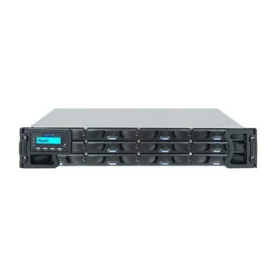
Figure 1-1: EonStor S12F Subsystem in a 2U chassis. The subsystem is powered by Infortrend’s proprietary ASIC400 RAID engine. By default, each RAID controller comes with a pre-installed 512MB DDR RAM DIMM module. Each 4Gb/s Fibre channel is capable of delivering data at the speed of 400MB/s. -
Page 16: Chassis Overview
EonStor S12F-R1432/G1433 Installation and Hardware Reference Manual • S12F-R1432: The dual controller model comes with redundant, dual-active RAID controllers which support all high-availability features including mirrored cache, controller failover/failback capability, and intelligent load-balancing between partner controllers. If one controller fails, the surviving controller automatically takes over in a way that is transparent to host. -
Page 17: Rear Panel Overview
Chapter 1: Introduction ․ Drive bays with drive tray canisters: The subsystem comes with twelve (12) drive bays in the front section of the chassis. Drive trays are designed to be hot-swappable. ․ LCD keypad panel and handles: The 2 rows x 16 characters-wide LCD panel is mounted on the left-side handle. -
Page 18: Internal Backplane
EonStor S12F-R1432/G1433 Installation and Hardware Reference Manual About the dual-redundant RAID controllers in S12F- R1432: There is a Primary-Secondary relationship between the dual- redundant RAID controllers. The upper RAID controller is identified as Controller A while the lower controller is identified as Controller B. -
Page 19: Physical Dimensions
Chapter 1: Introduction implemented in order to receive temperature/voltage readings and module presence signals. This board contains no user-serviceable components. WARNING! A physical contact with the backplane may cause a fatal damage to the RAID subsystem. For example, short-circuiting may occur if you accidentally touch the backplane with a screwdriver. -
Page 20: Drive Tray
EonStor S12F-R1432/G1433 Installation and Hardware Reference Manual indicators. The LCD front panel provides full access to all configuration and monitoring options. Figure 1-6: Forearm Handle Retention Latches To access drive bays in the left- or right-hand side column, first release the retention latches by pushing them outwards (as shown in the figure above), and then swing the forearm handles to the sides. -
Page 21: Mux Kit
Chapter 1: Introduction convenient release button ensures fast and efficient drive swapping. There are screw holes on the sides of the drive tray for securing hard drives to the drive tray. WARNING! Be careful not to warp, twist, or contort the drive tray in any way (e.g., by dropping it or resting heavy objects on it). - Page 22 EonStor S12F-R1432/G1433 Installation and Hardware Reference Manual Figure 1-10: Dual-ported SAS and Single-port SATA Connectors MUX kits are equipped with active-active port selectors to facilitate SATA drive installation and access from dual-active RAID controllers. See the figure below for how it works.
-
Page 23: The Raid Controller Module
Chapter 1: Introduction 1.3.4 The RAID Controller Module Figure 1-12: RAID Controller Within S12F-R1432 Figure 1-13: RAID Controller Within S12F-G1433 The RAID controller module that came with your subsystem contains a controller board, a BBU module bay, an interface faceplate, and a pre-installed 512MB DIMM module. -
Page 24: Controller Module Interfaces
EonStor S12F-R1432/G1433 Installation and Hardware Reference Manual 1.3.4.1 Controller Module Interfaces The controller interfaces are accessed through the controller’s rear- facing faceplate as shown below. Figure 1-14: RAID Controller Faceplate of S12F-R1432 Figure 1-15: RAID Controller Faceplate of S12F-G1433 ․... - Page 25 Chapter 1: Introduction ․ RJ-45 Fast Ethernet port: Each controller module on the S12F comes with 10/100BaseT Ethernet port local/remote management. When operated in the dual-active mode, system configuration is handled through one of the controllers. In the event when one controller fails, the Ethernet port on the surviving controller inherits the configured IP and continues the monitoring or configuration session.
-
Page 26: Dimm Module
EonStor S12F-R1432/G1433 Installation and Hardware Reference Manual default restoration in order to access data on the previously configured arrays. How to use the button? CAUTION! The Restore NVRAM Default push button should be considered as a last-resort function. Restoring firmware defaults will not destroy the existing logical drives;... -
Page 27: Bbu
Chapter 1: Introduction The 184-pin DDR RAM DIMM socket comes with a pre-installed 512MB capacity DDR RAM DIMM and is able to support a module with up to 2GB capacity. The DIMM module is accessed through an opening on the side of the controller canister. -
Page 28: Psus
EonStor S12F-R1432/G1433 Installation and Hardware Reference Manual In accordance with international transportation regulations, the BBU is only charged to between 35% and 45% of its total capacity when shipped. After powering on the subsystem, the BBU will automatically start charging its battery cells. It usually requires approximately twelve (12) hours for the battery to be fully charged. -
Page 29: Cooling Modules
Chapter 1: Introduction The S12F-R1432 is equipped with two (2) 530W PSUs (Figure 1-18), while S12F-G1433 is equipped with two (3) 350W PSUs (Figure 1- 19). The redundant, hot-swappable PSU modules are located at the rear of the enclosure. The PSU is permanently mounted into a 2U canister especially designed to house both the PSU and a cooling module. - Page 30 EonStor S12F-R1432/G1433 Installation and Hardware Reference Manual Figure 1-21: Cooling Module of S12F-G1433 Both S12F-R1433 and S12F-G1432 come with redundant cooling modules. Below are the details about the cooling modules: Model No. of No. of Location of No. of Location...
-
Page 31: Subsystem Monitoring
Chapter 1: Introduction 3. During the subsystem initialization stage, the cooling fans operate at the high speed and return to low speed once the initialization process is completed and that the subsystem has not discovered any erroneous conditions. Subsystem Monitoring The S12F subsystem comes with a number of different monitoring approaches that provide you with continual updates on the status of the subsystem and individual components. -
Page 32: Firmware (Fw) And Sanwatch Management Suite
EonStor S12F-R1432/G1433 Installation and Hardware Reference Manual 1.4.3 Firmware (FW) and SANWatch Management Suite Firmware: The firmware (FW) is pre-installed software used to configure the subsystem. The FW can be accessed either through the front LCD keypad panel or a terminal emulation program running on a management computer connected to the subsystem’s serial... -
Page 33: Components
Chapter 1: Introduction which can fail without leading to the loss of data will differ. Please see the table below. RAID Level Max. No. of Failed Drives RAID 0 No fault tolerance RAID 1 multiple (only if any two are not in a mirrored pair) RAID 3/5 RAID 6... - Page 34 EonStor S12F-R1432/G1433 Installation and Hardware Reference Manual This page is intentionally left blank. 1-20...
-
Page 35: Chapter 2 Hardware Installation
4. Cabling: All the fibre optical cables that connect the subsystem to the hosts should be purchased separately. It is recommended that you use certified fibre optical cables from Infortrend to avoid compatibility problems. You can find sample topologies and configuration options in Section 3.2. -
Page 36: Safety Precautions
EonStor S12F-R1432/G1433 Installation and Hardware Reference Manual 7. BBU: If you wish to install a BBU to S12F-G1433, the BBU must be purchased separately and installed prior to powering on the subsystem. (See Section 2.9) 8. Rack installation: The enclosure chassis can be installed into a rack cabinet using separately purchased mounting rails or Infortrend’s rackmount brackets. - Page 37 Chapter 2: Hardware Installation overloaded by the modules installed. Other requirements, such as ventilation airflow, rack stabilizing features, electrical earthing, and electrical distribution, must comply with the technical specifications listed in the documentation or safety label that came with this product.
-
Page 38: Static-Free Installation
EonStor S12F-R1432/G1433 Installation and Hardware Reference Manual 13. If any of the following situations occurs, contact service personnel: a. The power cord or plug is damaged. b. The equipments have been exposed to moisture. c. The enclosure has not worked well or you cannot get it work as the manual states. -
Page 39: Preparation
Chapter 2: Hardware Installation 2.3.3 Preparation ․ Make sure you are aware of the related positions of each plug- in module and interface connector. ․ Cables for connecting Fibre and SAS devices must be handled with care and must not be bent. To prevent emission interference within a rack system and accidental cable disconnection, the routing path must be carefully planned. -
Page 40: Installation Procedure Flowchart
EonStor S12F-R1432/G1433 Installation and Hardware Reference Manual 6. Power on: Once the components have been properly installed and all cables are properly connected, you can power on the subsystem and configure the RAID array. (See Section 4.1) 2.4.1 Installation Procedure Flowchart The figure below shows a flowchart of the installation procedure. -
Page 41: Preinstalled Components
The enclosure is designed to fit into a variety of 19-inch wide rack cabinets or racks. If you would like to purchase the rackmount rail kit from Infortrend, please contact your vendor. See the matching table below to find the suitable rail kit for your subsystem. -
Page 42: Rackmounting Procedure For S12F-R1432
EonStor S12F-R1432/G1433 Installation and Hardware Reference Manual Model Rack Depth Suitable Rail Kit S12F-R1432 22.64 to 36 inch IFT-9279CSlider36 S12F-G1433 21 to 28.5 inch IFT-9272CESlide28 25.5 to 36 inch IFT-9272CESlide36 Make sure you have an appropriate site location and cables prepared with adequate lengths to connect to main power and other devices. - Page 43 Chapter 2: Hardware Installation # 6-32 x 6mm Flat Head screws M5 cage nuts Filler plates behind forearm handles Table 2-1: Rackmount Kit Components Step 2. Determine the position where the subsystem is going to be installed on the rack. Place the bracket into the rack and slide the brackets to adjust them to the length between rack posts as shown below.
- Page 44 EonStor S12F-R1432/G1433 Installation and Hardware Reference Manual Step 5. Attach filler plates to the back of the enclosure’s left-side and right-side forearms with two (2) 6-32 L6 screws. Figure 2-5: Attaching Filler Plates Step 6. Gently slide the enclosure into the rack until you feel some resistance.
-
Page 45: Rackmounting Procedure For S12F-G1433
Chapter 2: Hardware Installation Figure 2-7: Securing the Subsystem 2.6.2 Rackmounting Procedure for S12F-G1433 Step 1. Verify the contents of your rail package. The package should include the following: Figure 2-8 Rackmount Kit Contents Item Description Quantity Left-side front bracket Right-side front bracket Left-side rear bracket Right-side rear bracket... - Page 46 EonStor S12F-R1432/G1433 Installation and Hardware Reference Manual Step 2. Assemble both the right-side and left-side front brackets with the rear brackets. When fitting the brackets, be sure to align the bracket joints on the front brackets with the pre-drilled holes on the rear brackets. (See the figure...
- Page 47 Chapter 2: Hardware Installation Figure 2-11: Adjusting Support Bracket Length Step 5. Pass two (2) M5 x 10mm Truss Head screws through the middle two (2) screw holes on front and rear sides of the support brackets, and then fasten the screws. There are cage nuts behind the screw holes.
- Page 48 EonStor S12F-R1432/G1433 Installation and Hardware Reference Manual Figure 2-13: Attaching Inner Brackets to the Chassis Step 7. Slide the enclosure into the rack. When mounting the enclosure into the rack, carefully orient the protruding edges of inner brackets so that they fit into the metal grooves on the support brackets.
-
Page 49: Hard Drive Installation
Chapter 2: Hardware Installation M5 x 30mm Pan Head screws through the holes. (See the figure below) Figure 2-15: Securing the Subsystem Hard Drive Installation 2.7.1 Hard Drive Installation Prerequisites Hard drives must be purchased separately. When you select hard drives, the following factors should be considered: Capacity (MB/GB): Use drives with the same capacity. -
Page 50: Drive Installation Without Mux Kit
EonStor S12F-R1432/G1433 Installation and Hardware Reference Manual SAS drives are preferred, you have to remove the MUX kits. (For the removal procedure of MUX kits, refer to Section 5.8, step 1-3) The single-controller S12F-G1433 subsystem can work with both SAS and SATA hard drives without MUX kits. -
Page 51: Drive Installation With Mux Kit
Chapter 2: Hardware Installation Step 2. Adjust the drive’s location until the mounting holes in the drive canister are aligned with those on the hard drive. Step 3. Secure the drive with four (4) of the supplied 6/32 flat- head screws. Please use the first and the fourth screw hole counted from the open side. -
Page 52: Drive Tray Installation
EonStor S12F-R1432/G1433 Installation and Hardware Reference Manual Figure 2-19: Screw Holes for Hard Drive Installation with MUX Drive Tray Installation Once the hard drives have been installed into the drive trays, the drive trays are ready to be installed into the subsystem. - Page 53 Chapter 2: Hardware Installation Figure 2-21: Opening the Drive Tray Front Flap Step 3. Align the drive tray with the drive bay into which you wish to insert it, and then slide it in. This should be done smoothly and gently. (See the figure below) Figure 2-22: Installing a Drive Tray Step 4.
-
Page 54: Bbu Installation
EonStor S12F-R1432/G1433 Installation and Hardware Reference Manual Figure 2-24: Drive Tray Lock Rotation BBU Installation (for the single-controller S12F-G1433) The BBU can sustain cache memory in the event of a power failure or in the unlikely event of failing both PSUs. The use of a BBU is highly recommended in order to avoid data inconsistency. -
Page 55: Installation Procedure
If this is discovered when you first use the BBU, return it to Infortrend or your system vendor. 2.9.2 Installation... - Page 56 EonStor S12F-R1432/G1433 Installation and Hardware Reference Manual Figure 2-27: BBU LED NOTE: A new or replaced BBU takes at least 12 hours to charge to its full capacity. You may check the BBU-related event messages on the LCD screen or your terminal console to make sure a BBU is successfully installed and starts charging.
-
Page 57: Chapter 3 Subsystem Connection
Chapter 3 Subsystem Connection This chapter outlines some general configuration rules you should use when configuring a storage system and introduces basic information about Fibre optical cables and Fibre Channel topologies for the subsystem. You can refer to these topologies or use them as a guide for developing your own unique topologies. -
Page 58: Fc Lasers
EonStor S12F-R1432/G1433 Installation and Hardware Reference Manual WARNING! All Fibre cables are sensitive and must be handled with care. To prevent interference within a rack system, the cable routing path must be carefully planned and the cables must not be bent. -
Page 59: Topology And Configuration Considerations
CAUTION! The SFP transceiver from Infortrend contains a laser diode featuring class 1 laser. To ensure continued safety, do not remove any covers or attempt to gain access to the inside of the product. Refer all servicing to qualified personnel. -
Page 60: Other Concerns
EonStor S12F-R1432/G1433 Installation and Hardware Reference Manual throughput on these data paths, it is necessary to apply Infortrend’s EonPath multi-pathing software. 3.1.5.3 Other Concerns ․ When you select the number of hard drives to be included in a logical configuration, the host channel bandwidth and the... -
Page 61: Sample Topologies
Do not overtighten or bend the cables. Sample Topologies The S12F subsystems supp ort Infortrend’s EonPath multi-pathing software. This software is necessary for controlling and optimizing the access to logical drives via redundant host channel paths. With TPGS support in the EonPath software, an optimal route is au tomatically lected for data distribution. - Page 62 EonStor S12F-R1432/G1433 Installation and Hardware Reference Manual Sample 1: DAS (Direct-Attached Storage) connections without redundant host paths, using single-controller S12F-G1433 Figure 3-2 : DAS Connectio with Non-fault to lerant Host Paths (S12F-G1433) Channels Controller A Host CH0 and CH1 Configuration Information...
- Page 63 Chapter 3: Subsystem Connection Figure 3-3: DAS Connections with Fault-tolerant Host Paths (S12F-G1433) Channels Controller A Host CH0 and CH1 Configuration Information RAID controllers Host servers Data path connection Fault-tolerant data paths Host channel bandwidth 800 MB/s Sample DAS (Direct-Attached Storage) connections with redundant host paths, using dual-controller S12F-R1432...
- Page 64 EonStor S12F-R1432/G1433 Installation and Hardware Reference Manual Figure 3-4: DAS Connections with Fault-tolerant Host Paths (S12F- R1432) Channels Controller A Controller B Host CH0 & CH1 CH0 & CH1 Configuration Information RAID controller Host server Data path connection Fault-tolerant Host channel bandwidth...
- Page 65 Chapter 3: Subsystem Connection IMPORTANT! If you connect fault-tolerant links via FC switches in a redundant- controller configuration, make sure the corresponding switch ports are configured as “FL_ports.” In the event when a RAID controller fails, a LIP is issued across and if the switched ports are configured otherwise, FC switches may not acknowledge the change in data routes.
-
Page 66: Cabling
EonStor S12F-R1432/G1433 Installation and Hardware Reference Manual Host server 2 (or more via FC switches) Data path connection Fault-tolerant paths Host channel bandwidth 1600MB/s Channel link bypass is provided on external FC switches. Each of the application servers shown in the diagram is equipped with two HBAs with FC links via two FC switches to the SFP ports on individual RAID controllers. -
Page 67: Expansion Links
Chapter 3: Subsystem Connection Figure 3-6: Connecting SFP Transceiver and LC Type Cables Step 7. Remove the protective caps on the other end of the cable and connect this end to an SFP transceiver module on a Fibre Channel switch port or a Fibre Channel host bus adapter (HBA) port. - Page 68 EonStor S12F-R1432/G1433 Installation and Hardware Reference Manual Figure 3-7: Connecting SAS JBODs with S12F-R1432 3-12...
-
Page 69: Single-Controller Raid To Single-Controller Jbods
Chapter 3: Subsystem Connection 3.4.1.2 Single-controller RAID to Single-controller JBODs The single-controller model, S12F-G1433, can connect up to 4 JBODs. Figure 3-8: Connecting Single-controller JBODs with S12F-G1433 3.4.1.3 Enclosure ID Settings There is a rotary ID switch on every expansion enclosure that is manually configured using a flat blade screwdriver. - Page 70 EonStor S12F-R1432/G1433 Installation and Hardware Reference Manual Make sure a unique ID is configured on each JBOD so that the SAS WWN addresses of disk drives can be properly assigned. RAID system firmware automatically manages these addresses. Figure 3-9: Setting the Enclosure ID...
-
Page 71: Chapter 4 Subsystem Operation And Monitoring
Chapter 4 Subsystem Operation and Monitoring Power On Once all of the disk drives have been properly installed and the I/O ports or management interfaces have been connected, the subsystem can be powered on. 4.1.1 Check List BEFORE powering on the subsystem, please check the following: Memory module: The cache memory usually comes as a pre- installed module. -
Page 72: Power On Procedure
EonStor S12F-R1432/G1433 Installation and Hardware Reference Manual 4.1.2 Power On Procedure When powering on the subsystem, please follow these steps: Step 1. Power on the Fibre Channel networking devices. These devices include FC switches and any other such devices connected between application servers and your RAID subsystem. -
Page 73: Power On Status Check
Chapter 4: Subsystem Operation and Monitoring Figure 4-2: Power Sockets and Power Switches on S12F-G1433 CAUTION! Although the PSUs are redundant and a single PSU can provide sufficient power to the system, it is advisable to turn on both power supplies. -
Page 74: Lcd Screen
EonStor S12F-R1432/G1433 Installation and Hardware Reference Manual 6. PSU LEDs: If the PSU is operating normally and experiencing no problem after being powered on, the LEDs on the PSU should light green constantly. 7. Firmware and SANWatch: Once the subsystem has been... -
Page 75: Power Off Procedure
Chapter 4: Subsystem Operation and Monitoring Initializing… This screen appears when the PSUs Please Wait... are turned on. Power On Self System is performing a self-test. Test, Please Wait… Power On The self-test has been completed. Init Completed This screen appears while partner RC Connecting…... -
Page 76: System Monitoring Overview
EonStor S12F-R1432/G1433 Installation and Hardware Reference Manual This prepares the RAID subsystem to be safely powered down. Step 3. Turn off the power. Power off the subsystem using the power switch on each PSU. Once the subsystem is powered down, other devices/enclosures connected to the subsystem can be sequentially powered down. -
Page 77: Status-Indicating Leds
Chapter 4: Subsystem Operation and Monitoring • Audible alarm: A beeper comes with the RAID controller board and will be triggered if any of a number of threatening events occurs. These events usually jeopardize the functional integrity of the controller board and must be heeded at all times. Events such as a breaching of the temperature threshold will trigger the alarm. -
Page 78: Drive Tray Leds
EonStor S12F-R1432/G1433 Installation and Hardware Reference Manual OFF indicates that no power is supplied to the subsystem or the subsystem has failed. FLASHING indicates that there is active traffic on the host/drive channels. BUSY White OFF indicates that there is no activity on the host/drive channels. -
Page 79: Controller Module Leds
Chapter 4: Subsystem Operation and Monitoring GREEN indicates that a drive is electrically connected in the drive tray. Green/ Power Status RED indicates that a drive has failed or is missing. Table 4-2: Drive Tray LED Definitions 4.4.3 Controller Module LEDs The controller faceplate is shown below. -
Page 80: System Status Leds
EonStor S12F-R1432/G1433 Installation and Hardware Reference Manual Figure 4-8: Controller LEDs on S12F-G1433 4.4.3.1 System Status LEDs The controller status LEDs are numbered from 1 to 6 and located on the controller’s rear-facing faceplate. (See Figure 4-7 and 4-8) The definitions are shown in the table below. -
Page 81: Fibre Port Leds
Chapter 4: Subsystem Operation and Monitoring - Battery voltage is lower than 2.5V. - Battery temperature reading is abnormal (out of the 0 to 45°C range). - Battery is not present. OFF indicates that the cache is clean, and that the battery backup unit is capable of sustaining memory in case of power loss. -
Page 82: Restore Default Led
EonStor S12F-R1432/G1433 Installation and Hardware Reference Manual 4.4.3.3 Restore Default LED A restore default LED is located beneath the restore default push button on the lower right corner of the controller faceplate. (See Figure 4-7 & 4-8) Before restoring defaults, use the “Save NVRAM”... -
Page 83: Psu Leds
Chapter 4: Subsystem Operation and Monitoring Figure 4-10: BBU LEDs on S12F-R1432 Figure 4-11: BBU LED on S12F-G1433 Color Status Flashing Amber The LED flashes to indicate the BBU is charging. Static Amber The BBU has failed. The BBU is fully charged and ready to sustain cached data. -
Page 84: Cooling Module Leds
EonStor S12F-R1432/G1433 Installation and Hardware Reference Manual Figure 4-13: PSU LED on S12F-G1433 Color Status Intermittent The power supply has not been turned on. The Flashing Green PSU LED flashes when the subsystem is connected to a power source but not yet turned on. - Page 85 Chapter 4: Subsystem Operation and Monitoring Figure 4-14: Cooling Module LEDs and Cooling Fan Locations on S12F-R1432 Figure 4-15: Cooling Module LEDs and Cooling Fan Locations on S12F-G1433 Color Status Static Amber ON: The cooling fan has failed. (S12F-R1432)/ OFF: The cooling fan operates normally. Static Red (S12F-G1433) Table 4-8: Cooling Module LED Definitions...
-
Page 86: Audible Alarm
EonStor S12F-R1432/G1433 Installation and Hardware Reference Manual Audible Alarm 4.5.1 Overview Different controller environmental and operational parameters (such as temperature and voltage) have been assigned a range of values between which they can fluctuate. If either the upper or lower threshold is exceeded, an audible alarm will automatically be triggered. -
Page 87: Overview
Chapter 5 Subsystem Maintenance and Upgrading Overview 5.1.1 About Subsystem Maintenance Constant monitoring and maintenance of your subsystem minimizes system downtime and preserves the working integrity of the system for a longer period of time. If any of the subsystem components fails, they must be replaced as soon as possible. -
Page 88: Replacing A Controller Module
EonStor S12F-R1432/G1433 Installation and Hardware Reference Manual maintenance in general, it is strongly advised that you refer subsystem maintenance to a qualified engineer. ․ Normalized airflow across heat-generating components depends upon the presence of all subsystem modules. A subsystem component, even if it has failed, should not be... -
Page 89: Considerations
Chapter 5: Subsystem Maintenance and Upgrading 5.2.1 nsiderations ․ The controller module contains a DIMM module. It is not recommended to re-use the DIMM module extracted from a failed controller unless you have a similar RAID subsystem that can be used to test the module. - Page 90 EonStor S12F-R1432/G1433 Installation and Hardware Reference Manual Figure 5-1: Removing the Controller Retention Screws Step 4. Remove the controller module by pressing down the two (2) levers simultaneously. The controller module will automatically ease out of the controller module bay.
- Page 91 Chapter 5: Subsystem Maintenance and Upgrading back-end connectors are engaging the backplane. (See the figure below) Figure 5-3: Installing the Controller Module Step 6. When the controller is fully inserted, pull the lever upward to secure the controller into chassis. (See the figure below) Figure 5-4: Using the Ejection Levers to Secure Controller Step 7.
-
Page 92: Replacing A Controller Module On S12F-G1433
EonStor S12F-R1432/G1433 Installation and Hardware Reference Manual 5.2.2.2 Replacing a Controller Module on S12F- G1433 To replace the controller module: Step 1. Prepare a clean, static-free work pad or container to place the removed controller. Step 2. Disconnect all cables from the failed controller module. -
Page 93: Replacing Adimm Module
Chapter 5: Subsystem Maintenance and Upgrading Step 6. Secure the controller module to the chassis by fastening the two (2) captive screws. Step 7. Re-attach all cables that were removed. These include the Fibre Channel host links, Ethernet cable to the management port, and serial cables to the COM ports. -
Page 94: Dimm Module Upgrade/Replacement Procedure
EonStor S12F-R1432/G1433 Installation and Hardware Reference Manual • Secure installation: When you re-install the controller module after replacing the DIMM module, make sure that the new DIMM module is firmly in place, or the subsystem will not be able to run. -
Page 95: Replacing A Faulty Bbu
Chapter 5: Subsystem Maintenance and Upgrading Figure 5-9: Removing a DIMM Module on S12F-G1433 Step 4. Insert the new DDR RAM DIMM module into the DIMM socket. Align the new module with the DIMM socket and note how the module is keyed. Firmly press the DIMM module into the socket, making sure the module is completely seated in the socket. -
Page 96: Bbu Warnings And Precautions
Charging will resume automatically if your remove and then re- install the BBU. 5.4.3 BBU Warnings and Precautions ․ Install or replace the BBU with BBUs supplied by Infortrend or your subsystem vendor only. U se of battery cells provided otherwise will void our warranty. ․... - Page 97 Chapter 5: Subsystem Maintenance and Upgrading causing functional defects, acid leak, and other hazardous results. ․ If a BBU leaks, gives off a bad odor, generates heat, becomes discolored or deformed, or in any way appears abnormal during use, recharging or storage, immediately remove it from the subsystem and stop using it.
- Page 98 EonStor S12F-R1432/G1433 Installation and Hardware Reference Manual Figure 5-12: Installing the BBU on S12F-R1432 Figure 5-13: Installing the BBU on S12F-G1433 Step 4. Reset the subsystem if the BBU is replaced online. After the system reset, the LED should start flashing to indicate that the BBU is being charged.
-
Page 99: 5.5 Replacing A Faulty Psu
The chance of charger failure is comparatively low. If the cause of a failure cannot be determined even after a BBU is replaced, contact your system vendor for a replacement controller and return the controller module through Infortrend’s standard RMA procedure. 5.5 Replacing a Faulty PSU WARNING! ․... - Page 100 EonStor S12F-R1432/G1433 Installation and Hardware Reference Manual Step 1. Turn off the faulty PSU. The power switch is located on the rear-facing panel of each PSU. (See the figures below) Figure 5-16: Locations of Power Sockets and Power Switches on...
- Page 101 Chapter 5: Subsystem Maintenance and Upgrading Figure 5-19: Removing the PSU Retention Screw on S12F-G1433 Step 4. For S12F-R1432, remove the PSU by grabbing the extraction handle and pulling the handle upwards. For S12F-G1433, remove the PSU by pushing the handle downwards.
-
Page 102: 5.6 Replacing A Faulty Cooling Module
EonStor S12F-R1432/G1433 Installation and Hardware Reference Manual WARNING! ․ When a PSU is removed from the chassis, the cooling module is also removed from the chassis. ․ It is recommended that the replacement procedure is completed in less than five (5) minutes to prevent the subsystem from overheating. -
Page 103: Cooling Module Replacement Procedure
Chapter 5: Subsystem Maintenance and Upgrading module for an extended period of time. If the cooling fans in the only remaining module fail, the subsystem will quickly overheat. ․ Detecting a failed cooling module: If a cooling module fails, the LED(s), an audible alarm, the embedded firmware utility, and the SANWatch software suite can notify you. - Page 104 EonStor S12F-R1432/G1433 Installation and Hardware Reference Manual Figure 5-22: Removing the Cooling Module on S12F-R1432 Step 3. Remove the retention screw on the side of PSU canister and push the release tab forward to disengage the cooling module. Step 4.
-
Page 105: Replacing A Cooling Module On S12F-G1433
Chapter 5: Subsystem Maintenance and Upgrading Step 7. Secure the module by fastening the six (6) screws previously removed from the top. Step 8. Reinstall the PSU module into chassis. Please refer to Section 5.5, Step 5-10 for how to install a PSU. 5.6.2.2 Replacing a Cooling Module on S12F-G1433 Step 1. -
Page 106: Hard Drive Replacement Procedure
EonStor S12F-R1432/G1433 Installation and Hardware Reference Manual for at least 30 seconds before you remove it from the subsystem. This can make the hard drive motor spin down before you take the drive out completely. Any impact to the hard drive while the drive motor is spinning can damage the hard drive. - Page 107 Chapter 5: Subsystem Maintenance and Upgrading Figure 5-24: Drive Tray Key-lock Rotation Step 3. Open the front flap by pushing the release button on the front flap of the drive tray. (See the figure below) The front flap will automatically spring open. Figure 5-25: Opening the Front Flap Step 4.
-
Page 108: Replacing Amux Kit
EonStor S12F-R1432/G1433 Installation and Hardware Reference Manual sides of the drive tray (two on each side). (See the figure below) Figure 5-27: Removing the Hard Drive Step 6. Install the replacement drive. Please refer to Section 2.7 for the complete hard drive installation procedures. - Page 109 Chapter 5: Subsystem Maintenance and Upgrading Figure 5-28: Removing the MUX Kit Retention Screws Step 4. Orient the replacement MUX kit and align its mounting holes with those on the drive tray. The SATA connector should face the front side and the SAS connector should face the rear side.
- Page 110 EonStor S12F-R1432/G1433 Installation and Hardware Reference Manual This page is intentionally left blank. 5-24...
-
Page 111: Appendix A Specifications
Appendix A Specifications Technical Specifications Environmental Specifications Operating: 5% to 90% (non-condensing) Humidity Non-operating: 5% to 95% (non-condensing) Operating: 0º to 40ºC (32º F to 104º F) Temperature Non-operating: -40º to 60ºC (-40º F to 149º F) Operating: Sea level to 3660m (12,000 ft.) Altitude Non-operating: Sea level to 12,192m (40,000 ft.) - Page 112 EonStor S12F-R1432/G1433 Installation and Hardware Reference Manual System Weight 18.71 kg (S12F-R1432) 23.5 kg (S12F-G1433) Gross 25.9kg (S12F-R1432) 25 kg (S12F-G1433) Shock Half-sine Operating: 5G peak, 11ms duration Non-operating: 15G, 11ms, half-sine Vibration Operating 0.5oct/min, 5 to 500Hz, sinewave, 0.2G Non- 0.5oct/min, 5 to 500Hz, sinewave, 1.0G...
-
Page 113: Functional Specifications
Drive Hot-swap drives Controller Hot- S12F-R1432 only swap capability Architectural Specifications PowerPC RISC processor DIMM Slot Female, right angle Memory Module ECC DIMM Supported ASIC Infortrend 64-bit chipset (ASIC400) Flash ROM 64Mbit (8MB) 128KB with RTC (with embedded RAIDWatch NVRAM utility) -
Page 114: Power Supply Specifications
EonStor S12F-R1432/G1433 Installation and Hardware Reference Manual Hardware XOR For event messages with time record and task Real-time Clock scheduling Power Supply Specifications Specifications 530W with active PFC (S12F-R1432) Nominal Power 350W with active PFC (S12F-G1433) S12F-R1432 12.0V: 43A (Max.) 5.0V: 25A (Max.) -
Page 115: Raid Management
Appendix A: Specifications Operating: -10 to +70ºC Storage: -30 to +70ºC S12F-G1433 Operating: -10 to +60ºC Storage: -20 to +70ºC RAID Management Specifications • Text-based firmware-embedded utility over RS-232C through the included serial cable; Y-cable for the dual-controller model. • Configuration Telnet via an established network connection... - Page 116 EonStor S12F-R1432/G1433 Installation and Hardware Reference Manual Automatic Rebuild on Spare Drives Regenerate Logical Drive Parity Bad Block Reassignment Automatic Rebuild upon Failed Drive Replacement Manual Clone of Suspected Failed Drive Concurrent Rebuild on Multiple Drives in a RAID (0 + 1) Logical...
-
Page 117: Appendix B Pinouts
Appendix B Pinouts SFP Connector Pinouts Each of the SFP host or expansion ports is comprised of a case bottom, an EMI case, and a 20-pin host connector. These port sockets receive Small-Form-Factor (SFP) fiber optical and copper- based transceivers. Please refer to the latest Interoperability Test Report for compatible modules that have been tested to comply with the sockets. -
Page 118: Com1 Serial Port Cable: Db9 And Audio Jack Pinouts
EonStor S12F-R1432/G1433 Installation and Hardware Reference Manual MOD_DEF Module Definition 2: Data line for Serial ID MOD_DEF Module Definition 1: Clock line for Serial ID MOD_DEF Module Definition 0: Grounded within the module Rate Select No connection required Loss of signal indication; Logic 0 indicates... -
Page 119: Com1 Serial Port Cable: Db9 Audio Jack Y-Cable Pinouts
Appendix C: Pinouts Figure C-2: COM1 Serial Port Cable P2 Pin Number Pin Name P1 Pin Number Pin Name DTR (Shorted) DSR (Shorted) RTS (Shorted) CTS (Shorted) Table C-2: COM1 Serial Port Cable Pinout Definitions COM1 Serial Port Cable: DB9 Audio Jack Y-Cable Pinouts The 2-audio jacks to DB9 Y-cable connects the COM1 serial ports on the redundant RAID controllers for maintenance-free terminal... -
Page 120: Com2 Serial Port Cable To Ups: Db9
EonStor S12F-R1432/G1433 Installation and Hardware Reference Manual Figure C-3: COM1 Serial Port Y-Cable CN2 & CN3 Pin Pin Name Number CN1 Pin Number Pin Name DTR (Shorted) DSR (Shorted) RTS (Shorted) CTS (Shorted) Table C-3: COM1 Y-Cable Pinout Definitions COM2 Serial Port Cable to UPS: DB9... - Page 121 Appendix C: Pinouts Figure C-4: COM2 Adapter Cable Connector Pinouts CN1 Pin Number Pin Name CN2 Pin Number Pin Name NA(Shorted with Pin6) NA(Shorted with Pin4) NA(Shorted with Pin8) NA(Shorted with Pin7) Table C-4: COM2 Adapter Cable Pinout Definitions...
-
Page 122: And Audio Jack Y-Cable Pinouts
EonStor S12F-R1432/G1433 Installation and Hardware Reference Manual COM2 Serial Port Cable to UPS: DB9 and Audio Jack Y-cable Pinouts Figure C-5: Connector Pinouts - Adapter Cable for COM2 CN2 & CN3 Pin Pin Name Number CN1 Pin Number Pin Name... -
Page 123: Ethernet Port Pinouts
Appendix C: Pinouts Figure C-6: Null Modem Pinouts Swap pin 2 and pin 3 Swap pin 4 and pin 6 Swap pin 7 and pin 8 Table C-6: Null Modem Pinouts Ethernet Port Pinouts Figure C-7: Ethernet Port Pinouts Pin Name Pin Name LAN_TXP LAN_TXN... -
Page 124: Power Connectors
EonStor S12F-R1432/G1433 Installation and Hardware Reference Manual Power Connectors IEC-type receptacle.
Need help?
Do you have a question about the EonStor S12F-R1432 and is the answer not in the manual?
Questions and answers