
Subscribe to Our Youtube Channel
Related Manuals for Infortrend EonStor A16F


Summary of Contents for Infortrend EonStor A16F
- Page 1 Infortrend EonStor A16F/A16U Quick Installation Guide EonStor A16F/A16U Quick Installation Guide P/N MA16FA6R11 Ver.1.1...
-
Page 2: Important Note
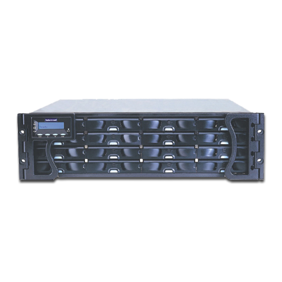
This quick installation guide can be used to install the following Infortrend SATA RAID controller storage subsystems: . EonStor A16U-G1A3 (single controller, SCSI-to-SATA) . EonStor A16F-G1A2 (single controller, FC-to-SATA) and . EonStor A16F-R1A2 (dual-redundant controller, FC-to-SATA) All the pre-installed and uninstalled items (that users are required to install) are listed on Page 1. - Page 3 Quick Installation Guide Pre-installed items include: 1.Cooling FAN Modules 2.Power Supply Units (PSU) 3.The DIMM Module Items to be installed: 1. Battery Backup Unit (BBU) (Optional for single controller subsystems) 2. Controller Module 3. Dongle/MUX Kits 4. Hard Drives (HDDs) 5.
-
Page 4: Battery Backup Unit (Bbu) Installation
Quick Installation Guide Battery Backup Unit (BBU) Installation Inset NOTE: spacers The BBU is installed in the controller module, directly above the DIMM. Prior to installing the BBU, make sure that a DIMM has been installed on the controller board. Figure 1: Insert Spacers To install the BBU please follow these steps:... -
Page 5: Controller Module Installation
Quick Installation Guide Controller Module Installation Note: Before installing the controller module please ensure that both the BBU and the SDRAM DIMM Modules have been Edge installed. Notch Ejector To install the controller module, please Handle follow these steps: Figure 4: Inserting the Controller Module Step 1: Hold the RAID controller unit by its edges and insert it into the controller bay. -
Page 6: Hard Drive Installation
Quick Installation Guide Step 3: Place the dongle/MUX kit at the back of the drive tray. Hold the dongle kit in place and turn the drive tray over. Align the Retention Screws holes in the base of the drive tray with the holes in the dongle /MUX kit base tray. -
Page 7: Drive Tray Installation
Quick Installation Guide Step 2: Once the connectors from the dongle board have been firmly attached to the hard drive, place the hard drive into the drive tray as shown in Figure 10. Step 3: Adjust the drive's location until the mounting holes in the drive canister are aligned with those on the hard drive. -
Page 8: Subsystem Cable Connections
RS-232C UPS support. Two audio jack to DB9 (Audio Jack) cables are provided to facilitate the connection of these serial ports. Figure 16: EonStor A16F-S1A2 Controller Rear View RJ-45 Ethernet Port: The RS-232C Audio Jack serial ports can Expansion Hosts be used to assign a permanent IP to the EonStor subsystem. - Page 9 Quick Installation Guide Expansion: Power Switch Power Switch The redundant controller modules come with a third SFP connector (see Figure 17) for subsystem expansion. This SFP connector can be connected to an external JBOD to help increase the overall capacity of the storage network.
- Page 10 Quick Installation Guide...
- Page 11 Quick Installation Guide...
- Page 12 3150 Coronado Dr., Unit C Santa Clara, CA 95054 Tel: 408-988-5088 Fax: 408-988-6288 sales@infortrend.com support@infortrend.com http://www.infortrend.com Asia Pacific Infortrend Technology, Inc. 8F, No. 102 Chung-Shan Rd., Sec. 3 Chung-Ho City, Taipei Hsien, Taiwan Tel: (886)-2-2226-0126 Fax: (886)-2-2226-0020 sales@infortrend.com.tw support@infortrend.com.tw http://www.infortrend.com.tw China Infortrend Technology, Ltd.
Need help?
Do you have a question about the EonStor A16F and is the answer not in the manual?
Questions and answers