
Related Manuals for Infortrend EonStor U16U-G4010


Summary of Contents for Infortrend EonStor U16U-G4010
- Page 1 EonStor U16U-G4010 320MB/sec SCSI-to-SCSI RAID Subsystem Installation and Hardware Reference Manual Revision: 1.1 ®...
-
Page 2: Contact Information
EonStor U16U Installation and Hardware Reference Manual Contact Information Asia Pacific Americas (International headquarter) Infortrend Technology, Inc. Infortrend Corporation 8F, No. 102 Chung-Shan Rd., Sec. 3 3150 Coronado Drive, Unit C Chung-Ho City, Taipei Hsien, Taiwan Santa Clara, CA 95054, USA... - Page 3 Trademarks Infortrend Infortrend logo registered trademarks Infortrend Technology, Inc.. EonStor and other names prefixed with “IFT” and “ES” are trademarks of Infortrend Technology, Inc. ® PowerPC is a trademark of International Business Machines Corporation and Motorola Inc. Solaris and Java are trademarks of Sun Microsystems, Inc.
- Page 4 Use only shielded cables to connect I/O devices to this equipment. You are cautioned that changes or modifications not expressly approved by the party responsible for compliance could void your authority to operate the equipment. This device is in conformity with the EMC EonStor U16U-G4010 - iv -...
-
Page 5: Table Of Contents
1.8. Connector Type, Supported Connections and Other Information ..........1-15 Chapter 2: Installation ....................2-1 2.1. Chapter Overview........................2-1 2.2. Installation Pre-requisites ......................2-2 2.3. Safety Precautions ........................2-2 2.3.1 General Considerations ....................2-2 2.3.2 Precautions Handling Other Modules:................2-3 EonStor U16U-G4010 - v -... - Page 6 3.3.6 LCD Panel ........................3-6 3.3.7 Drive Tray LEDs......................3-7 3.4. RAIDWatch Manager........................3-8 3.5. Notification Processing Center (NPC)..................3-8 3.6. Audible Alarm ..........................3-8 3.6.1 Default Threshold Values ....................3-8 3.6.2 Failed Devices ........................ 3-9 EonStor U16U-G4010 - vi -...
- Page 7 5.5. Cooling FAN Module Maintenance ..................5-11 5.5.1 Notes on Cooling FAN Module Maintenance ............... 5-11 5.5.2 Replacing a Cooling FAN Module................5-12 5.6. Drive Tray Maintenance......................5-13 5.6.1 Notes on Hard Drive Maintenance ................5-13 EonStor U16U-G4010 - vii -...
- Page 8 B.7. Fault Tolerance Management ......................B-4 Appendix C: Packaging ....................C-1 C.1. Appendix Overview........................C-1 C.2. Overview .............................C-2 C.3. Container Contents ........................C-3 C.3.1 Accessory Box .........................C-3 C.3.2 HDD Tray Box ........................C-3 C.3.3 Controller Box ........................C-3 C.3.4 Enclosure Box .........................C-4 EonStor U16U-G4010 - viii -...
- Page 9 D.3. Accessories ..........................D-4 Appendix E: Pin-outs....................E-1 E.1. Appendix Overview........................E-1 E.2. SCSI Port Pin-outs........................E-2 E.3. Controller Interfaces ........................E-3 E.3.1 DB-9 Serial Port Pinouts ....................E-3 E.3.2 Ethernet Port Pin-outs ....................E-3 E.4. Mains Power..........................E-4 E.5. I C Port............................E-4 EonStor U16U-G4010 - ix -...
-
Page 10: Esd Precautions
If it is necessary to transport the subsystem, repackage all drives and replaceable modules separately. ESD Precautions Observe all conventional anti-ESD methods while handling system modules. The use of grounded wrist-strap and an anti-static work pad are recommended. Avoid dust or debris in your work area. EonStor U16U-G4010 - x -... -
Page 11: About This Manual
Replacement of failed battery modules and DIMM modules are also described. ♦ Appendix A: EonStor U16U Features This appendix describes a few of the many features of the ES U16U. ♦ Appendix B: EonStor U16U Specifications EonStor U16U-G4010 - xi -... -
Page 12: Related Documentation
Warnings should be taken seriously. Warnings are easy to recognize. The word “warning” is written as “WARNING”, both capitalized and bold and is followed by text in italics. The italicized text is the warning message. EonStor U16U-G4010 - xii -... - Page 13 Software and Firmware Updates Please contact your system vendor or visit Infortrend’s FTP site (ftp.infortrend.com.tw) for the latest software or firmware updates. NOTE that the firmware version installed on your system should provide the complete functionality listed in the specification sheet/user’s manual.
- Page 14 EonStor U16U Installation and Hardware Reference Manual This page has intentionally been left blank. EonStor U16U-G4010 - xiv -...
-
Page 15: Chapter 1: Introduction
Chapter 1: Introduction Chapter 1: Introduction 1.1. Chapter Overview This chapter:- 1. Introduces the 3U, 16 Bay, SCSI-to-SCSI EonStor (ES) subsystems (ES U16U). 2. Introduces the model variations. 3. Introduces the different active components on the subsystem. 4. Introduces the different monitoring techniques. After reading this chapter a user should:- 1. -
Page 16: Product Overview
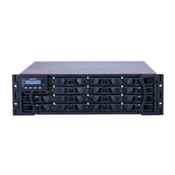
EonStor U16U Installation and Hardware Reference Manual 1.2. Product Overview 1.2.1 Product Introduction This hardware manual briefly introduces the EonStor (ES) U16U-G4010 (ES U16U) SCSI-to-SCSI storage subsystems shown in Figure 1-1. Figure 1-1: ES U16U storage subsystem The ES U16U subsystem series comes in four models (see Table 1-1). All the models come with two 320MB/sec SCSI (SCSI-320) host channels and are able to support up to 16, hot-swappable, SCSI-320 hard drives. -
Page 17: Enclosure Chassis
Chapter 1: Introduction ES U16UG4010 -42-0030 -45-0030 -62-0030 -65-0030 Host Channels 2 x SCSI-320 2 x SCSI-320 2 x SCSI-320 2 x SCSI-320 (CH0 and CH1) Drive Channel 2 x SCSI-320 2 x SCSI-320 2 x SCSI-320 2 x SCSI-320 (CH2 and CH3) Expansion Channels 2 x SCSI-320... - Page 18 EonStor U16U Installation and Hardware Reference Manual Channel Type Channel Assignment Host CH0 and CH1 Drive CH2 and CH3 Expansion (Configured as drive channels) CH4 and CH5 Table 1-2: Channel Pre-configurations The following two diagrams show the data paths for the six channel and four channel models.
-
Page 19: Es Subsystem Components
Chapter 1: Introduction Figure 1-3: Data Path Diagram – RAID Array Enclosure 1.3. ES Subsystem Components All the active components on the ES subsystems can be accessed through either the front or rear panel. The modular design of the active components facilitates their easy installation and removal. -
Page 20: Rear Panel Overview
EonStor U16U Installation and Hardware Reference Manual 1.3.2 Rear Panel Overview The rear panel of the RAID subsystems described in this manual is shown in Figure 1-5. A description of each rear panel component is given below. Figure 1-5: ES U16U Subsystem Rear View The rear panel shown in Figure 1-5 is designed to accommodate the following components: ♦... -
Page 21: Front Panel Components
Chapter 1: Introduction 1.4. Front Panel Components 1.4.1 LCD Panel Figure1-6: LCD Panel The LCD panel shown in Figure1-6 consists of a 16x2 character LCD screen with push buttons and LED status indicators. The LCD front panel provides full access to all RAID configurations and monitoring. -
Page 22: Rear Panel Components
EonStor U16U Installation and Hardware Reference Manual 1.5. Rear Panel Components 1.5.1 The RAID Controller Module The RAID controller module contains a main circuit board, necessary support interfaces and an optional BBU. The controller module contains no user-serviceable components. Except when replacing a faulty unit, installing a BBU or installing/upgrading the cache memory inside the controller module should never be removed or opened. - Page 23 Chapter 1: Introduction 1.5.1.3 Host IO Board The host IO board is mounted on the IFT-3260 controller board by the way of two board-to-board connectors and secured to the controller with six retention screws. Four retention screws are inserted into spacers which are connected to the controller board.
-
Page 24: Battery Backup Unit
EonStor U16U Installation and Hardware Reference Manual NOTE: SCSI termination: SCSI termination is automatically set when a cable is connected to a SCSI port. There is no need to change the terminator settings on SCSI channels using the configuration options in firmware. The same applies to JBOD enclosures. ♦... -
Page 25: I 2 C Enclosure Monitoring
Chapter 1: Introduction Figure 1-10: BBU Module If a user intends to install a BBU, a battery charger board (IFT-9070E) shown in Figure 1-11 must initially be mounted on the controller board. The battery charger board comes with a connector that is attached to the BBU Figure 1-11: Battery Charger Board 1.5.2 I 2 C Enclosure Monitoring: Various sensors and components within the enclosure are linked by an I... - Page 26 EonStor U16U Installation and Hardware Reference Manual Figure1-12: PSU Module Rear View Each PSU comes with a single power socket for power cord plug-in and is attached to a single power switch located directly above it that will enable users to turn the PSU on and off.
-
Page 27: Cooling Fan Modules
Chapter 1: Introduction 1.5.4 Cooling fan modules ES U16U subsystems come with two 1U dual-blower, redundant, hot-swappable cooling fan modules, shown in Figure 1-13, pre-installed in the subsystem. Two 9.7cm blowers are housed in each cooling module and can provide a total of 61 CFM of airflow running at the speed of 3600rpm. -
Page 28: Firmware (Fw) And Raidwatch Gui
EonStor U16U Installation and Hardware Reference Manual ♦ RAID Controller ♦ LCD Panel ♦ Cooling FAN Module ♦ PSU Module ♦ Drive Trays 1.6.3 Firmware (FW) and RAIDWatch GUI Firmware:- The firmware is pre-installed software that is used to configure the subsystem. -
Page 29: Normalized Airflow
Chapter 1: Introduction ♦ The power supply units (PSUs) ♦ The cooling fan modules ♦ The hard drives 1.7.3 Normalized Airflow Proper subsystem cooling is referred to as “normalized” airflow. Normalized airflow is required to ensure the sufficient cooling of the subsystem and is only attained when all the components are properly installed. - Page 30 EonStor U16U Installation and Hardware Reference Manual This page has intentionally been left blank. 1-16 Connector Type, Supported Connections and Other Information...
-
Page 31: Chapter 2: Installation
Chapter 2: Installation Chapter 2: Installation 2.1. Chapter Overview CAUTION Please note that the installation instructions described in this manual should be carefully followed. If they are not carefully followed, the system may be damaged. This chapter:- 1. Discusses installation pre-requisites. 2. -
Page 32: Installation Pre-Requisites
EonStor U16U Installation and Hardware Reference Manual 2.2. Installation Pre-requisites 1. Static Free Installation Environment – The ES subsystem must be installed in a static free environment to minimize the possibility of electrostatic discharge (ESD) damage. (See Section 2.3.3). 2. Component Check – Before the ES subsystem is installed, users should, during the unpacking process, check to see that they have received all the required components. -
Page 33: Precautions Handling Other Modules
Chapter 2: Installation ♦ Handling the Subsystem Modules - Handle the system modules by the retention screws, eject levers, or the module’s metal frame/face plate only, avoid touching the PCB boards or connector pins. ♦ Covers - None of the covers or replaceable modules should be removed for the compliance with safety, emission, or thermal requirements. -
Page 34: Static-Free Installation
EonStor U16U Installation and Hardware Reference Manual ♦ Note on using RAID - No RAID system is 100 percent fault-proof, routine backup of your data is still necessary. 2.3.3 Static-Free Installation Static electricity can damage the electronic components of the system. Most of the controllers that are returned for repair are the results of improper installation and ESD damage. -
Page 35: General Installation Procedure
Chapter 2: Installation ♦ IO port cabling - All series models are equipped with 0.8mm VHDCI SCSI connectors. Please contact our technical support for an updated list of host adapters that have been tested and proved compatible with the ES U16U series. ♦... -
Page 36: Unpacking The Subsystem
EonStor U16U Installation and Hardware Reference Manual Step 8. Cable connection – Use the power cables that came with the subsystem to connect to the subsystem to the mains. Use separately purchased SCSI cables to connect the host ports to the host computers. (See Chapter 4) Step 9. -
Page 37: Memory Module Installation/Upgrade
Chapter 2: Installation ♦ Midplane ♦ Driveplane Accessory items are placed on top of the controller modules. They include power cords, Audio Jack cable and a CD containing both the Hardware Manual (this document) and the RAIDWatch User’s Manual. 2.6. Memory Module Installation/Upgrade The ES subsystem comes with pre-installed SDRAM DIMMs. -
Page 38: Dimm Module Upgrade Procedure
EonStor U16U Installation and Hardware Reference Manual ♦ SDRAM DIMM modules supported – The ES subsystems are able to support SDRAM DIMMs with memory capacities 256MB and 1GB. ♦ Installation Considerations – When installing the SDRAM DIMM module, it is necessary to handle the controller module. - Page 39 Chapter 2: Installation Figure 2-1: Remove the Retention Screws Step 3. Remove the Optional BBU and charger board– If a BBU has been installed on the IO board, both the BBU and the charger board should be removed. To remove the BBU disconnect the BBU connector from the battery charger. Note: the retention screws that connect the BBU to the IO board were removed in Step 3 above.
- Page 40 EonStor U16U Installation and Hardware Reference Manual When lifting the IO board it is best to elevate the back end of the board and then, before sliding it out of the module, place it at a slight angle to the controller module (see Figure 2-3).
- Page 41 Chapter 2: Installation Step 8. Replace the IO board – Hold the back of the board in an elevated position, angle the board at a slight angle to the controller module and gently slide the host IO board into the controller module (see Figure 2-5). First ensure that the front panel interfaces are correctly aligned with their respective locations on the controller module rear panel.
-
Page 42: Bbu Installation
EonStor U16U Installation and Hardware Reference Manual 2.7. BBU Installation 2.7.1 About the BBU Installation Users are free to purchase an optional BBU module that is able to sustain a 512MB cache memory for up to 72 hours in the event of a power failure or in the (extremely unlikely) event of both PSUs failing. - Page 43 Chapter 2: Installation Figure 2-6: Remove the Battery connector cap Step 3. Mount the Battery Charger Board – The BBU module will come with a battery charger board. This is connected to the controller board through two board-to- board connectors. Correctly orient the charger board and align its board-to-board connectors with those on the controller board as shown in Figure 2-7.
- Page 44 EonStor U16U Installation and Hardware Reference Manual Step 4. Remove two IO Board retention screws – The BBU is attached to the controller module with two retention screws. These screws are already used to connect the IO board to the controller board. If the controller rear panel is facing you, these screws can be found on the right hand side of the IO board.
-
Page 45: Installing The Raid Controller Module
Chapter 2: Installation 2.8. Installing the RAID Controller Module To install the controller module, please follow these steps: Step 1. Hold the RAID controller unit by its edges and insert it into the controller bay. Push the unit in until it reaches the end of the controller bay. The guide rails on the sides of the controller bay should make the plug-in process an effort-less task. -
Page 46: Slide Rail Availability
2.9.2 Slide Rail Availability Infortrend currently provides two slide rails for ES U16U rack-mounting. These slide rails, which are listed below, must be purchased separately as accessory items. The available slide rails are: ♦... -
Page 47: Hard Drive Installation
Chapter 2: Installation ♦ Capacity (MB / GB) –Use drives with the same capacity. RAID arrays use a “least- common-denominator” approach. The maximum capacity of each drive the array can use is the maximum capacity of the smallest drive. Choose big drives of the same size. - Page 48 EonStor U16U Installation and Hardware Reference Manual Step 1. Make sure the key-lock is in the unlocked position. The key-lock is unlocked if the groove (on its face) is in a horizontal orientation. If the groove is in a vertical position, as shown in Figure 2- 4 then the key-lock is locked and the front flap on the drive tray cannot be opened.
- Page 49 Chapter 2: Installation Figure 2- 6: Drive Tray Key-Lock Rotation WARNING: All the drive trays (even if they do not contain a hard drive) must be installed into the enclosure. If they are not installed into the enclosure then the ventilation required for cooling will not be normalized and the subsystem will be irreparably damaged.
- Page 50 EonStor U16U Installation and Hardware Reference Manual This page has intentionally been left blank. 2-20...
-
Page 51: Chapter 3: Subsystem Monitoring
Chapter 3: Subsystem Monitoring Chapter 3: Subsystem Monitoring 3.1. Chapter Overview This chapter:- 1. Introduces the different ES subsystem monitoring techniques. 2. Gives detailed descriptions and definitions of status indicating LEDs 3. Describes the audible alarm and events that may cause it to trigger. 4. -
Page 52: Subsystem Monitoring Overview
EonStor U16U Installation and Hardware Reference Manual 3.2. Subsystem Monitoring Overview The ES subsystem is equipped with a variety of self-monitoring features that help to keep subsystem managers informed of the subsystem operational status. These monitoring features provide vital feedback that helps users maintain the operational integrity of the subsystem. -
Page 53: Status Indicating Leds
Chapter 3: Subsystem Monitoring appropriate action to rectify the problem. Failure to act in a properly specified manner to a system event (like overheating) can cause severe and permanent damage to the subsystem. 3.3. Status Indicating LEDs 3.3.1 Brief Overview of the LEDs The following devices all come with LEDs that are used to inform subsystem managers about the operational status of the component on which they are mounted. -
Page 54: Lan Port Leds
EonStor U16U Installation and Hardware Reference Manual Name Color Status ON indicates the BBU has failed and cannot sustain the cache memory. BBU Fail Amber FLASHING indicates the BBU is charging. OFF indicates the BBU can sustain the cache memory. (Note: If a BBU has not been installed then this LED will not function.) ON indicates there is activity Green... -
Page 55: Cooling Fan Module Led
Chapter 3: Subsystem Monitoring Figure 3-3: PSU Module Rear LED Color Status Static Green The PSU is operating normally and experiencing no problems Static Red The PSU has failed and is unable to continue providing power to the subsystem. The power supply has not been turned on. The PSU module LED will remain off even if the power cable has been plugged in but the power switch not turned on. -
Page 56: Lcd Panel
EonStor U16U Installation and Hardware Reference Manual The cooling FAN modules each have two red LEDs on the back. Each LED corresponds to a single fan in the cooling FAN module (see Figure 3-4). When the LED is ON it indicates that the fan has failed. -
Page 57: Drive Tray Leds
Chapter 3: Subsystem Monitoring LED Name Color Status ON indicates that the power is being supplied to the Blue subsystem. OFF indicates that no power is being supplied to the subsystem. ON indicates that there is activity on the host/drive channels. BUSY White OFF indicates that there is no activity on the host/drive... -
Page 58: Raidwatch Manager
EonStor U16U Installation and Hardware Reference Manual 3.4. RAIDWatch Manager The RAIDWatch Manager enables users to manage and maintain the RAID Controllers using their web browsers. The Ethernet port at the back of each controller module enable users to use a LAN cable to connect to the subsystem. The RAIDWatch Panel View is a specialized customization that shows a direct representation of the ES U16U in the content panel of the RAIDWatch screen. -
Page 59: Failed Devices
Chapter 3: Subsystem Monitoring Parameter Upper Threshold Lower Threshold +3.3V +3.6V +2.9V +5.5V +4.5V +12V +13.2V +10.8V CPU Temperature 90ºC 0ºC Board Temperature 90ºC 0ºC Table 3-7: Default Threshold Values The thresholds in Table 3-7 are the default threshold values. The user can change these values. - Page 60 EonStor U16U Installation and Hardware Reference Manual Corresponding to the redundant power supplies, there are two power switches on EonStor enclosures. The I C connector is located near the power switch on the upper left corner of enclosure rear panel. Once connected, the RAID system will automatically poll the serial bus for component status, including that of the temperature sensors, cooling fans, power supplies, and slot status.
-
Page 61: Chapter 4: Subsystem Connection And Operation
Chapter 4: Subsystem Connection and Operation Chapter 4: Subsystem Connection and Operation 4.1 Chapter Overview This chapter:- 1. Describes how to operate the ES subsystem. 2. Describes how to connect the ES subsystem to external devices. 3. Briefly introduces FC topologies, SFP connectors, lasers etc. 4. -
Page 62: Eonstor U16U Subsystem Host Connection
EonStor U16U Installation and Hardware Reference Manual 4.2 EonStor U16U Subsystem Host Connection 4.2.1 SCSI Cable s One SCSI cable (IFT-9270UHstCab) is provided with the ES U16U for host connection. If a user wishes to use a second SCSI cable to connect the second host channel, a second cable must be purchased independently. -
Page 63: Operation Considerations
Chapter 4: Subsystem Connection and Operation Figure 4-2: Dual host Connection 4.2.3 Operation C onsiderations NOTE: To create dual redundant data paths on the host side, it is necessary for third party failover software to be installed on the host computer/s. ♦... - Page 64 EonStor U16U Installation and Hardware Reference Manual Figure 4-3: Subsystem Expansion EonStor U16U Subsystem Host Connection...
-
Page 65: Power On
Chapter 4: Subsystem Connection and Operation 4.3 Power On Once all the components have been installed in the EonStor subsystem and the host channels have been connected to the host and the expansion cables have been connected to the JBODs, the subsystem can be powered on. 4.3.1 Check List BEFORE powering on the ES U16U subsystem, please check the following: Memory Modules –... -
Page 66: Eonstor Power On-Procedure
EonStor U16U Installation and Hardware Reference Manual 3. Host Computers The host computers should be the last devices that are turned on. Please refer to the manual that came with your host computers to see its own power on procedure 4.3.3 EonStor Po wer On-Procedure To power on the subsystem, turn the two power switches, on the rear panel of the subsystem (see Figure 4- 1). -
Page 67: Lcd Screen
Chapter 4: Subsystem Connection and Operation Drive tray LEDs should normally start flashing, indicating the RAID control units are attempting to access the hard drives. System firmware supports configuration of a delayed sequence for starting drives. Please consult your Generic Operation Manual for more details. NOTE: The subsystem has been designed to run continuously. -
Page 68: Power Off Procedure
EonStor U16U Installation and Hardware Reference Manual System is ready. You can now start to configure the ES U16UG v3.31F subsystem. No Host LUN 4.4 Power Off Procedure If you wish to power down the EonStor subsystem, please follow these steps: NOTE: If you wish to power down the EonStor subsystem, please ensure that no time-consuming processes, like a “logical drive parity”... -
Page 69: Chapter 5: Subsystem Maintenance
Chapter 5: Subsystem Maintenance Chapter 5: Subsystem Maintenance 5.1. Chapter Overview This chapter:- 1. Introduces how to maintain an ES subsystem. 2. Describes how to maintain the controller module. 3. Describes how to hotswap the active components in the subsystem. After reading this chapter a user should:- 1. -
Page 70: Overview
EonStor U16U Installation and Hardware Reference Manual 5.2. Overview 5.2.1 About Subsystem Maintenance Constant monitoring and maintenance of your ES U16U subsystem will minimize the chance of system downtime and preserve the working integrity of the system for a longer period of time. -
Page 71: Controller Module Maintenance
Chapter 5: Subsystem Maintenance ♦ When replacing any hot-swappable component, caution should be taken to ensure that the components are handled in an appropriate manner. The manhandling of components can lead to irreparable damage. ♦ When removing a controller module from the subsystem, ensure that the power has been turned off and that all precautionary measures, without exception, are adhered to. -
Page 72: Replacing A Failed Controller Module
EonStor U16U Installation and Hardware Reference Manual ♦ Prior to replacing the controller module it is imperative for your own safety and that of the subsystem that no power is being supplied to the system. 5.3.3 Replacing a Failed Controller Module A controller module can fail for a variety of reasons: either the controller board has sustained serious damage or the host IO board has been damaged in some severe way. - Page 73 Chapter 5: Subsystem Maintenance Figure 5-1: Loosen Controller Module Retention Screws Step 4. Pull the Controller module Out – Once the retention screw have been loosened, open the rear flap and gently pull the controller module out of the ES U16U chassis.
-
Page 74: Bbu And Bbu Charger Board Replacement
EonStor U16U Installation and Hardware Reference Manual Step 10. Connect the Controller Module Cables – Connect all of the cables that were previously disconnected from the controller module. These may include SCSI cables for host connection, RS-232C cable for serial port connection and an Ethernet cable for LAN connection. - Page 75 Chapter 5: Subsystem Maintenance Figure 5-2: Disconnect the BBU Connector Step 6. IF THE BBU FAILED Remove the retention screws – The bracket of BBU is attached to the IO board through two retention screws that pass through the bracket, IO board and spacers that connect the IO board to the controller board. Remove these screws.
-
Page 76: Dimm Module Replacement
EonStor U16U Installation and Hardware Reference Manual Step 9. Connect the BBU to the Charger board – Connect the BBU cable to the connector on the charger board. Step 10. Install the controller module – Once new BBU has been installed in to the controller module, insert the controller module into the controller bay at the rear of the subsystem. -
Page 77: Replacing A Failed Psu Module
Chapter 5: Subsystem Maintenance transferred from the old controller module to the replacement. Instructions for replacing a controller module have been given in Section 5.3.3 above. 5.4. Replacing a Failed PSU Module 5.4.1 Notes on PSU Module Maintenance ♦ Two redundant PSU modules - The ES comes with two fully redundant, hot- swappable PSU modules. - Page 78 EonStor U16U Installation and Hardware Reference Manual Figure 5-4: Removing the PSU Retention Screw 4. A clip can be seen at the top left-hand corner of the PSU. This clip is used to secure the PSU into the subsystem enclosure. To remove the PSU, push this clip towards the right.
-
Page 79: Cooling Fan Module Maintenance
Chapter 5: Subsystem Maintenance 5. After the PSU module has been dislodged from the enclosure, use the handle at the rear of the PSU to gently pull the PSU module out of the enclosure. (See Figure 5-6) Figure 5-6: Removing the PSU from the subsystem 6. -
Page 80: Replacing A Cooling Fan Module
EonStor U16U Installation and Hardware Reference Manual ♦ Two Redundant Cooling FAN modules - The ES subsystem is equipped with two redundant, hot-swappable, dual-blower cooling FAN modules located above the PSU modules. These cooling FAN modules are responsible for controlling the internal operational temperature of the subsystem and therefore their working integrity should be maintained at all times. -
Page 81: Drive Tray Maintenance
Chapter 5: Subsystem Maintenance Figure 5-7: Removing the Cooling FAN Module 3. Once the damaged/broken cooling FAN module has been removed, gently slide the new cooling FAN module into the EonStor chassis. 4. Re-insert both the retention screws that were previously removed. 5.6. -
Page 82: Hdd Replacement
EonStor U16U Installation and Hardware Reference Manual disrupted and subsystem components will overheat and may be permanently damaged. 5.6.2 HDD Replacement If one of the hard drives fails it needs to be replaced. To replace a hard-drive please follow these steps. 1. -
Page 83: Appendix A: Eonstor U16U Features
Appendix A: EonStor U16U Features Appendix A: EonStor U16U Features A.1. Appendix Overview This Appendix:- 1. Introduces the flexible configuration options of the ES U16U subsystems. 2. Introduces some of the Redundant Features. 3. Describes some of the fault tolerant features 4. -
Page 84: Overview
EonStor U16U Installation and Hardware Reference Manual A.2. Overview The ES U16U RAID Subsystem comes with many different features. Some of these features enhance the performance of the system, other features add configuration flexibility and other features simplify the installation, maintenance and upgrade procedures of the system. -
Page 85: Fault Tolerance
Appendix A: EonStor U16U Features A.4. Fault Tolerance A.4.1 Intelligent Drive Handling Media Scan is an innovative Intelligent Drive Handling function that can be used for data retrieval from degraded or damaged hard drives. If two bad blocks occur on two member drives of an array, the integrity of the stored data will be endangered. -
Page 86: Other Fault Tolerant Features
EonStor U16U Installation and Hardware Reference Manual detect only, clone and replace, and perpetual clone. A faulty drive can be cloned to an active spare upon the discovery of errors. A.4.6 Other Fault Tolerant Features Other comprehensive failure management features on the EonStor RAID Subsystem include: •... -
Page 87: Appendix B: Specifications
Appendix B: Specifications Appendix B: Specifications B.1. Appendix Overview This Appendix provides:- 1. Technical Specifications 2. Controller Specifications 3. Drive Tray Specifications 4. Power Supply Specifications 5. RAID Management 6. Fault Tolerance Management After reading this Appendix a user should:- 1. -
Page 88: Technical Specifications
EonStor U16U Installation and Hardware Reference Manual B.2. Technical Specifications RAID Controller Module Specifications PowerPC 750CXe 400MHz with 256KB of internal L2 running at Main Processor the processor’s core speed Host Channel Interface Two SCSI-320 SCSI channels Drive Interface Support for Sixteen (16) SCSI-320 drives RAID Controlling Unit Architectural Features: •... - Page 89 Appendix B: Specifications Power Requirements 90VAC @ 8AC Input Voltage 260VAC @ 4AC with PFC (auto-switching) Frequency 47 – 63Hz Power Capacity 460W Dimensions Height 131 mm Width 447 mm 500 mm Length EMI/EMC • FCC Class-B • • Shock Half-sine Operating: 5G peak, 11ms duration, Non-operating: 15G, 11s, half-sine...
-
Page 90: Raid Operation Specifications
EonStor U16U Installation and Hardware Reference Manual B.3. RAID Operation Specifications B.3.1 Configuration Specification RAID Levels 0, 1(0 + 1), 3, 5, 10, 30, 50, JBOD, and Non-RAID disk spanning Host O/S Host O/S Independent Compatibility Host Interface SCSI-320 Host Channels Pre-configured host channels Drive Interface Support 16 SCSI-320 drives... -
Page 91: Raid Management
B.7. Fault Tolerance Management Specification Yes (with user-configurable detect only, clone and replace Drive S.M.A.R.T Support and perpetual clone functions). Battery Back-up option ISEMS (Infortrend Simple Enclosure Management Service) via I C interface Automatic Drive Failure Detection Automatic rebuild on spare drives... - Page 92 EonStor U16U Installation and Hardware Reference Manual drive Salvage the 2 temporary failed drive in a RAID 1, 3 or 5 logical drive Salvage the 1 temporary failed drive in a RAID 0 logical drive...
-
Page 93: Appendix C: Packaging
Appendix C: Packaging Appendix C: Packaging C.1. Appendix Overview This Appendix:- 1. Describes the subsystem packaging. 2. Lists components that can be found in the contrainer. After reading this Appendix a user should:- 1. Be able to check that all the components arrived with the subsystem. Appendix Overview... -
Page 94: Overview
EonStor U16U Installation and Hardware Reference Manual C.2. Overview The EonStor subsystem is packed in 7 boxes as shown Figure C-1. Six boxes are, as seen in Figure C-1, placed in a single container box. The subsystem chassis is placed right at the bottom of the box. -
Page 95: Container Contents
Appendix C: Packaging C.3. Container Contents C.3.1 Accessory Box The accessories box should contain the items shown in Table C-1. ES U16U Quantity Power Cords SCSI Host Cable GUI CD Pack Screws for Mounting Drives Null Modem Screws for Mounting Enclosure & rack 12 (4 x M6, 4 x M5, 4 x #10-32 Quick Installation Guide Table C-1: ES U16U Packaging... -
Page 96: Enclosure Box
EonStor U16U Installation and Hardware Reference Manual C.3.4 Enclosure Box The enclosure box comes with two EP foam blocks that are used to fix the chassis within the bottom of the box. The Enclosure Chassis contains the components shown below. ♦... -
Page 97: Appendix D: Spare Parts And Accessories
Appendix D: Spare Parts and Accessories Appendix D: Spare Parts and Accessories D.1. Appendix Overview This Appendix lists:- 1. Shared spare parts 2. Single-Controller Model Only Spare Parts 3. Single-Upgradable/Dual-Redundant Model Only Spare Parts 4. Shared accessories 5. Single-Controller Model Only Accessories After reading this Appendix a user should:- 1. -
Page 98: Spare Parts
EonStor U16U Installation and Hardware Reference Manual D.2. Spare Parts D.2.1 Controller Modules The controller modules, part number and controller module contents are all shown in Table D-1 below. All the controller modules described below are installed in a metal canister. -
Page 99: General Spare Parts
Appendix D: Spare Parts and Accessories D.2.2 General Spare Parts The spare parts listed in Table D-2 can be used for the following subsystems: Spare Part Model Name Description HDD Tray IFT-9270CDTray EonStor 3U series hard drive tray. PSU Module IFT-9270CPSU 1U 460W power supply unit. -
Page 100: Accessories
EonStor U16U Installation and Hardware Reference Manual D.3. Accessories The ES U16U accessories are listed in Table D-3. Spare Part Model Name Description BBU Module IFT-9270UBT BBU Module can sustain 512Mb DIMM memory for 72 hours SCSI Cable IFT-9270UHstCab SCSI cable for U16U to host, SCSI 68 pins to VHDCI SCSI Cable IFT-9270CDCCAB9... -
Page 101: Appendix E: Pin-Outs
Appendix E: Pin-outs Appendix E: Pin-outs E.1. Appendix Overview This Appendix lists:- 1. The pin outs for the different external interfaces on the subsystem After reading this Appendix a user should:- 1. Be able to determine the pin outs on the external interfaces of the subystem. -
Page 102: Scsi Port Pin-Outs
EonStor U16U Installation and Hardware Reference Manual E.2. SCSI Port Pin-outs SCSI port pin-out definitions are shown in Table E-1. * NC=No Connection, * GND=Ground, * TPWR=Terminator Power Name Name SD12+ SD12- SD13+ SD13- SD14+ SD14- SD15+ SD15- SDP1+ SDP1- SD0+ SD0- SD1+... -
Page 103: Controller Interfaces
Appendix E: Pin-outs E.3. Controller Interfaces E.3.1 DB-9 Serial Port Pinouts The DB-9 serial port pin-outs are shown in Figure E-1 and their definitions are given in Table E-2. Figure E-1: DB-9 Serial Port Pin Name Pin Description Transmitter positive Power 5V No connection N/C (keylocked) -
Page 104: Mains Power
EonStor U16U Installation and Hardware Reference Manual E.4. Mains Power IEC type receptacle. E.5. I C Port RJ-11 Modular phone jack connector pin-outs are shown in Table E-4. Pin Number Pin Name Pin Number Pin Name Pin1 I2CCLK Pin3 Pin2 Pin4 I2CDATA Table E-4: I... - Page 105 Index cooling fan module LED, 3-5 --A-- cooling fan module maintenance, 5-11 cooling fan module replacement, 5-12 accessory items, 2-7 cooling fan module, 1-2, 1-3, 1-6,1-13, 2-5, airflow, 2-2, 2-3 3-3, 3-6 audible alarm, 1-14, 3-2, 3-8, 3-9 audio jack cable, 2-7 --D-- auto shutdown, A-3 auto switch cache policy, A-3...
- Page 106 Index faulty unit, 2-3 local Spare, A-3 firmware, 1-14, 3-2, 4-6 lower level, 2-6 flush the cache, 4-8 --M-- front flap, 2-18 front panel, 1-5 maintenance, 5-2 front section, 1-3 Media Scan, A-3 memory module, 2-2, 2-7, 4-5 --G-- midplane, 1-3 Generic Operation Manual, 3-9 model variations, 1-2, A-2 global spare, A-3...
- Page 107 Index regeneration of parity, A-4 subsystem features, A-2 RJ-45 port, 1-10 --T-- RS-232C serial port, 1-10 temperature threshold, 3-2 --S-- terminal emulation program, 1-14 S.M.A.R.T, A-3 --U-- SCSI cable, 4-2 SCSI termination, 1-10 unpack, 2-2, 2-5, 2-6 SCSI-320 channel, 1-3 upper level, 2-6 SCSI-320 drive channel, 1-10, A-2 --V--...
- Page 108 Index This page has intentionally been left blank.
Need help?
Do you have a question about the EonStor U16U-G4010 and is the answer not in the manual?
Questions and answers