Table of Contents
Advertisement
Quick Links
Advertisement
Table of Contents

Related Manuals for Infortrend EonStor GS 3000 Series


Summary of Contents for Infortrend EonStor GS 3000 Series
- Page 1 Infortrend EonStor GS 3000 Series Hardware Manual Version 1.0...
-
Page 2: Legal Information
Infortrend, shall be subject to the latest Standard Warranty Policy available on the Infortrend website: http://www.infortrend.com/global/Support/Warranty Infortrend may from time to time modify, update or upgrade the software, firmware or any accompanying user documentation without any prior notice. Infortrend will provide access to these new software, firmware or documentation releases from certain download sections of our website or through our service partners. -
Page 3: Contact Information
435 Lakeside Dr. Sunnyvale, CA. 94085, USA Tel: +1-408-988-5088 Fax: +1-408-988-6288 Email, Technical Support, Website Infortrend Technology, Ltd. / Infortrend 北京分公司 China 北京市朝阳区东四环中路远洋国际中心 D 座 403 室 Room 403,Block D, Ocean International Center, Dis. Chaoyang, Beijing, China Tel: +86-10-6310-6168 Fax: +86-10-59648252 Email,... -
Page 4: Copyright Notice
Infortrend Technology, Inc. Disclaimer Infortrend Technology makes no representations or warranties with respect to the contents hereof and specifically disclaims any implied warranties of merchantability or fitness for any particular purpose. Furthermore, Infortrend... -
Page 5: Safety Precautions
Safety Precautions Safety Precautions Read these instructions carefully before you install, operate, or transport the EonStor GS RAID system and JBODs. Installation and Operation Install the rack cabinet and the associated equipment at a site where the ambient temperature (special room cooling equipment may be required) stays lower than: a. -
Page 6: Service And Maintenance
The use of Infortrend certified components is strongly recommended to ensure compatibility, quality and normal operation with your Infortrend products. Please contact your distributor for a list of Infortrend certified components (e.g. SFP, SFP+, HBA card, iSCSI cable, FC cable, memory module, etc.). -
Page 7: Esd Precautions
ESD Precautions ESD Precautions Handle the modules by their retention screws, ejector levers, or the module’s metal frame/faceplate only. Avoid touching the PCB boards or connector pins. Use a grounded wrist strap and an anti-static work pad to discharge static electricity when installing or operating the enclosure. -
Page 8: About This Manual
About This Manual About This Manual The manual introduces hardware components of EonStor GS RAID and JBOD systems. It also describes how to install, monitor, and maintain them. For non-serviceable components, please contact our support sites. Firmware operation: Consult the Firmware User Manual on the CD-ROM. EonOne software: Consult the EonOne User Manual on the CD-ROM. -
Page 9: Table Of Contents
Table Of Contents Legal Information ..................2 Contact Information ................... 3 Copyright Notice ..................4 Safety Precautions ..................5 Installation and Operation ................. 5 Service and Maintenance ................6 Important Notice ..................6 ESD Precautions ..................7 About This Manual..................8 Revision History .................. - Page 10 Internal Backplane ..................24 Front Panel Components ................ 25 LED Panel ....................25 Drive Tray Bezel ..................26 Rear Panel Components ................. 27 Controller Module of RAID Models ............. 27 Super Capacitor & Flash Backup Module ..........29 PSU & Cooling Module ................30 System Monitoring Features ..............
- Page 11 Fibre-Host Connections (including 10Gb FCOE iSCSI) ......49 Fibre-Host Topologies ................51 Fibre Cabling ..................... 52 Simple End-to-End Connection ..............53 DAS (Direct-Attached) Connection ............54 Switched Fabric Connection (Dual-Controller) ........... 56 Switched Fabric Connection (Single-Controller) ......... 58 SAS-Host RAID Connections ..............60 DAS (Direct-Attached Storage) Connection with Redundant Host Path ..
- Page 12 Controller LED ..................90 Controller LED for RAID Models ..............90 Controller LED for 12 Gb/s SAS JBOD Models .......... 92 iSCSI / Ethernet Management Port LEDs ..........93 10 Gb iSCSI Host Port LEDs (Fibre) ............94 10 Gb iSCSI Host Port LEDs (RJ45) ............94 8 Gb Fibre-Host Port LEDs ................
- Page 13 Certifications..................124 Summary ....................124 Slide Rail Kit Installation Guide ............125 Slide Rail Kits ..................125 Enclosure Installation Prerequisites ............ 125 Unpacking the System ................126 Component Installation Procedure ............126 Tools Required ..................126 Rack Ear Mount Kit ................127 Kit Contents .....................
-
Page 14: Introduction
Introduction Product Overview This manual introduces EonStor GS 3000 systems that support 3Gbps, 6Gbps and 12Gbps SAS and Near Line SAS, SATA hard drives and SSDs. The enclosure is designed to utilize 2.5” or 3.5” hard drives. Drive capacity can be expanded by attaching expansion hard drive enclosures (JBODs). -
Page 15: Model Variations
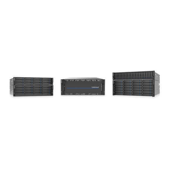
EonStor GS 3012 EonStor GS 3016 EonStor GS 3024B Model Variations Comprised of RAID and JBOD models, RAID systems store hard drives and control the entire storage array while JBOD systems connect to a master RAID system and allow storage capacity expansion by adding more hard drives. Hard drive limitation(s) may vary model to model. -
Page 16: Major Components
Major Components NOTE Upon receiving your system, check the package contents against the included Unpacking List. If module(s) are missing, please contact your system vendor immediately. RAID Controller and Interface Each RAID controller comes with pre-installed DIMM module(s). The traditional battery backup is replaced by an innovative Cache Backup Module methodology (CBM) which consists of a super capacitor and a flash backup module (FBM). -
Page 17: Power Supply Unit With Built-In Cooling Module
Power supply unit with built-in cooling module Cooling module is built into the power supply unit (PSU) to protect the system from overheating. The two hot-swappable PSUs provide constant power to the system. The modular nature of the system and the easy accessibility to all major components ensure ease of maintenance. -
Page 18: The Rear Panel
The Rear Panel Dual-Controller Models Dual-Controller systems are indicated by an “R” in their model number (please refer Model Naming Conventions). Controller A is located on top and controller B at the bottom for all models. If one controller fails, the second controller module will take over in a manner that is transparent to application servers. -
Page 19: Single-Controller Models
Single-Controller Models Single-Controller models are designated by a “G” or “S” in their model number. The second controller slot is filled with a dummy cage. EonStor GS 3012 / 3024B EonStor GS 3016 Upgrading Single-Controller to Dual-Controller System If the model name of a Single-Controller RAID/JBOD is designated with the letter “S”, it can be upgraded into a Dual-Controller configuration by adding another controller module and firmware upgrade (see software manual). -
Page 20: Chassis
Chassis The chassis is rugged constructed and divided into front and rear sections. The chassis is designed to be installed into a rack or cabinet. Front Panel EonStor GS 3012 EonStor GS 3016 EonStor GS 3024B... - Page 21 Hard drive trays (1): Each drive tray is hot-swappable and holds a 2.5 / 3.5-inch hard drive. 4U60 systems have 3 drawers, holding 20 hard drives in each drawer LED Panel (2): The panel has Service / Power / Cooling Fan / Thermal / System LEDs.
-
Page 22: Rear Panel
Rear Panel Description Description Controller A Power supply + cooling module Controller B EonStor GS 3012 / 3024B EonStor GS 3016... - Page 23 Controllers (1) / (2): Each RAID controller module contains a main circuit board and a pre-installed DIMM module. For Single-Controllers, a dummy cage will be placed at the controller (2) position. The host port configurations will vary. For details, see Rear Panel Components.
-
Page 24: Internal Backplane
Internal Backplane An integrated backplane separates the front and rear sections of the chassis. This circuit board provides logic level signals and low voltage power paths. Thermal sensors and I C devices are embedded to detect system temperatures and PSU/cooling module operating status. This board contains no user-serviceable components. -
Page 25: Front Panel Components
Front Panel Components LED Panel ES GS 3000 LED panel The LED panel can be located on the chassis ear. The LED panel contains Service LED (1), a power supply status LED (2), cooling module status LED (3), temperature sensor status LED (4), System fault LED (5), Mute Service button (6), rotary ID switch (only JBOD) (7). -
Page 26: Drive Tray Bezel
Drive Tray Bezel 3.5 inch 2.5 inch The drive tray is designed to accommodate separately purchased SAS or SATA interface hard disk drives. There is a release button (1) that has to be used to retrieve disk drives from the chassis. To the right of the bezel plate, there is a drive busy LED (2) and a power status LED (3). -
Page 27: Rear Panel Components
Rear Panel Components Controller Module of RAID Models Designation Description Designation Description Host ports Controller status LED Super capacitor Ethernet 1G management port SAS 12G expansion port Serial port (RS-232) Restore default button USB port Restore default LED The controller also features a Cache Backup Module (CBM), consisting of a super capacitor and a Flash Backup Module (FBM). - Page 28 WARNING The only time you should remove the controller is to install/ replace the CBM or a failed controller. The RAID controller is built of sensitive components and unnecessary tampering may damage the controller.
-
Page 29: Super Capacitor & Flash Backup Module
Super Capacitor & Flash Backup Module The super capacitor (1) and flash backup module (2) can be located inside the controller and serves as a Cache Backup Module (CBM) described in the previous section. With the super capacitor, the cached data can be stored permanently in the flash backup module, in case of a power outage. -
Page 30: Psu & Cooling Module
PSU & Cooling Module The two redundant, hot-swappable PSUs have a power socket (1), power switch (2), PSU status LED (3), cooling module (4), retention screw (5) and an extraction handle (6). The cooling modules can operate at three rotation speed settings. Under normal operating conditions, the cooling fans run at the low speed. -
Page 31: System Monitoring Features
System Monitoring Features There are a number of monitoring approaches that provide the operating status of individual components. Expansion Enclosure Support Monitoring: A managing RAID system is aware of the status of JBOD components including those of: Expander controller (presence, voltage and thermal readings) ... -
Page 32: I 2 C Bus
JBOD Enclosure Status Monitoring: A RAID system, when connected with expansion JBODs, acquires the component status within other enclosures via a proprietary enclosure monitoring service using the in-band connectivity. No additional management connection is required. C bus The detection circuitry and temperature sensors are interfaced through a non-user-serviceable I C bus. -
Page 33: Hot-Swapping
Hot-swapping The system comes with a number of hot-swappable components that can be exchanged while the system is still online without affecting the operational integrity. These components should only be removed from the system when they have to be replaced. The following components can be user-maintained and hot-swappable: ... -
Page 34: Hardware Installation
Hardware Installation This chapter describes how to install modular components, such as hard drives into the enclosure and CMB into RAID controller enclosure. NOTE Installation into a rack or cabinet should occur BEFORE hard drives are installed into the system. Installation Prerequisites Static-free installation environment: The system must be installed in a static-free environment to minimize the possibility of electrostatic discharge (ESD) damage. -
Page 35: Installation Procedures Overview
Installation Procedures Overview Following all the instructions provided below can minimize system installation time. Detailed, illustrated instructions for each component are given in the following sections. 1. Unpack: Unpack the system and confirm all components have been received against the Unpacking List. 2. -
Page 36: Unpacking The System
Unpacking the System Compare the Unpacking List included in the shipping package against the actual package contents to confirm that all required materials have arrived. Box contents For detail content(s), please refer to the unpacking list that came with the system. The accessory items include a serial port cable, screws, Quick Installation Guide, a CD containing the EonOne management software and its manual and Firmware Operation Manual, and a product utility CD containing the Installation and... -
Page 37: Installing Hard Drives
Installing Hard Drives Installation of hard drives should only occur after the enclosure has been rack-mounted! Hard Drive Installation Prerequisites Hard drives are separately purchased and when purchasing hard drives, the following factors should be considered: Capacity (MB/GB): Use drives with the same capacity. RAID arrays use a “least-common-denominator”... - Page 38 MUX Board: Shown below, controller A (1) and controller B (2) is connected to the backplane (3). With a MUX board (4) paired to the hard drive (5), data signals is able to switch between controllers A and B signal ports (indicated by the blue arrow / dotted line). Under normal circumstances, controller B signal port is in standby mode (6).
-
Page 39: Sas Interface
SAS Interface The SAS interface features a dual-ported connectivity with pins on both sides of its connector that include SAS primary links (1), power link (2) and underneath it, the SAS secondary links (3). The SATA drives have only one port that includes the SATA physical links (4) and the power link (5). -
Page 40: Hard Drive Designation
Hard Drive Designation Illustrations shown below are system hard drive slot number designations. Please familiarize yourself with the designations to avoid withdrawing the hard drive(s) out of the enclosure. 2U: EonStor GS 3012 2U: EonStor GS 3024B 3U: EonStor GS 3016... -
Page 41: Installing The Hard Drive Into Drive Tray
Installing the Hard Drive into Drive Tray Open the bezel by pressing the release button and gently pull out the tray. 3.5 inch 2.5 inch Place the hard drive into the drive tray, making sure that the interface connector is facing the open side of the drive tray and its label side facing up. -
Page 42: Installing The Hard Drive Tray Into The Enclosure
Installing the Hard Drive Tray into the Enclosure Once the hard drives have been installed in the drive trays, install the drive trays into the system. WARNING Each drive bay must be populated with a tray even if it does not contain a hard drive. An empty bay will disrupt ventilation and the system might overheat. -
Page 43: Installing Host Boards
Installing Host Boards NOTE As an upgrade to existing Single-Controller systems, down time may occur! Please install one controller at a time. ALWAYS install to the left host board slot (close to SAS Exp.) first before installing to the right host board slot! If you want to install a different host board than currently installed, make sure that you replace both host boards. -
Page 44: Installing The Controller
Installing the Controller Insert the controller slowly into the module slot. When you feel the contact resistance, use slightly more force and then push both of the ejection levers upwards (indicated by the blue arrows) to secure the controller into chassis. Secure the controller by fastening the two retention screws (1) under the ejection levers (2). -
Page 45: System Connection
System Connection This chapter outlines the general configuration rules you should follow when cabling a storage system and introduces basic information about topologies. You can use these topologies or refer to them as a guide for developing your own unique topologies. -
Page 46: Host-Side Topologies
A spare drive should have a minimum capacity that is equivalent to the largest drive that it is expected to replace. If the capacity of the spare is less than the capacity of the drive it is expected to replace, the controller will not proceed with the failed drive rebuild. -
Page 47: Maximum Concurrent Host Lun Connection ("Nexus" In Scsi)
Maximum Concurrent Host LUN Connection (“Nexus” in SCSI) The "Max Number of Concurrent Host-LUN Connection" menu option is used to set the maximum number of concurrent host-LUN connections. Maximum concurrent host LUN connection (nexus in SCSI) is the arrangement of the controller internal resources for use with a number of the current host nexus. -
Page 48: Maximum Queued I/O Count
Maximum Queued I/O Count The "Maximum Queued I/O Count" menu option enables you to configure the maximum number of I/O operations per host channel that can be accepted from servers. The predefined range is from 1 to 1024 I/O operations per host channel, or you can choose the "Auto"... -
Page 49: Fibre-Host Connections (Including 10Gb Fcoe Iscsi)
Fibre-Host Connections (including 10Gb FCOE iSCSI) WARNING All Fibre cables are sensitive and must be handled with care. To avoid interference, the cable routing path must be carefully planned and the cables must not be bent. The Fibre Channel standard allows optical connections. Optical cables can be used over longer distances and have been shown to be more reliable. - Page 50 WARNING The SFP transceiver contains a laser diode featuring class 1 laser. To ensure continued safety, do not remove any covers or attempt to gain access to the inside of the product. Refer all servicing to qualified personnel. FC port dust plugs Each FC port comes with a dust plug.
-
Page 51: Fibre-Host Topologies
Fibre-Host Topologies The Fibre Channel standard supports three (3) separate topologies. They are point-to-point, Fibre Channel Arbitrated Loop (FC-AL), and fabric switch topologies. Point-to-Point: Point-to-point topology is the simplest topology. It is a direct connection between two (2) Fibre Channel devices. ... -
Page 52: Fibre Cabling
Fibre Cabling Following are steps that should be completed with cabling: Maintain a configuration plan. In addition to cabling topologies and list of networking components, the plan can also include firmware and software maintenance details. Confirm that you have a Fibre Channel cable that loops 6-inch or longer. Ensure proper airflow and keep cables away from ventilation airflow outlets. -
Page 53: Simple End-To-End Connection
Simple End-to-End Connection HBA 0 HBA 0 HBA 1 HBA 1 EonPath EonPath CH0 B113 CH2 A112 CH2 B113 CH0 A112 CH3 A112 CH3 B113 CH1 B113 CH1 A112 CH2 A112 CH2 B113 CH0 A112 CH0 B113 CH1 B113 CH1 A112 CH3 A112 CH3 B113 RAID... -
Page 54: Das (Direct-Attached) Connection
DAS (Direct-Attached) Connection NOTE If a logical drive has to be accessed by different servers, file locking, FC switch zoning, port binding, and multipath access control will be necessary in order to avoid access contention. HBA 0 HBA 0 HBA 1 HBA 1 EonPath EonPath... - Page 55 With more disk drives over SAS expansion links, you can create more logical groups of drives. These logical drives using more host channel IDs or LUN numbers. If a server has multiple data paths to a RAID system, a multi-path software is necessary, e.g., the EonPath driver.
-
Page 56: Switched Fabric Connection (Dual-Controller)
Switched Fabric Connection (Dual-Controller) NOTE A logical partition presented through LUN Mapping can be seen by all servers across SAN. Make sure you have access control such as file-locking, switch zoning, port binding, etc., to avoid access contention. HBA 0 HBA 1 HBA 0 HBA 1... - Page 57 Channel link bypass is provided on external FC switches. Each of the application servers shown in the diagram is equipped with two HBAs with FC links via two FC switches to the SFP ports on individual RAID controllers. You can refer to the ID tags on the host links to see the related logical volume mapping and cable links routing paths.
-
Page 58: Switched Fabric Connection (Single-Controller)
Switched Fabric Connection (Single-Controller) HBA 0 HBA 0 HBA 1 HBA 1 EonPath EonPath CH0 B114 CH1 B114 CH0 A112 CH1 A112 CH0 B113 CH1 B113 CH1 A115 CH0 A115 7 8 9 1011 12 7 8 9 1011 12 1 2 3 4 5 6 1 2 3 4 5 6 CH0 A112... - Page 59 Above is the sample drawing showing connections with each SFP port connected to FC switches and then to host adapters. See logical associations in the drawing for LUN mapping details. Use Enclosure-specific spares to prevent a spare drive from participating in the rebuild of a logical drive on another enclosure.
-
Page 60: Sas-Host Raid Connections
SAS-Host RAID Connections Please contact your vendor to purchase compatible host-link cables. SAS cables (28AWG x 8 pairs) are characterized by 100ohm, black colors, UL-approved, lead-free, 50, 120 or 170cm cable lengths; connectors can be secured to chassis receptacle using latching mechanism. WARNING All SAS cables are sensitive and must be handled with care. -
Page 61: Das (Direct-Attached Storage) Connection With Redundant Host Path
DAS (Direct-Attached Storage) Connection with Redundant Host Path HBA 0 HBA 1 EonPath EonPath CH0 AID CH0 AID CH0 AID CH0 AID CH0 AID CH1 BID CH0 AID CH0 BID CH0 AID CH1 AID CH0 AID CH1 AID CH1 BID CH0 BID CH0 BID CH1 BID... - Page 62 HBA 0 HBA 1 EonPath CH0 AID CH1 AID CH0 AID CH1 AID RAID Single-Controller models With more hard drives over SAS expansion links, you can create more logical groups of drives. Avail these logical partitions using more LUN numbers. NOTE EonPath multipath software or Linux Device Mapper is necessary for controlling and optimizing the access to logical drives via multiple data paths.
-
Page 63: Das (Direct-Attached Storage) Connection To Two Servers
DAS (Direct-Attached Storage) Connection to Two Servers CH0 AID CH1 AID CH1 AID CH0 AID RAID NOTE If you would like a LUN (a logical partition) to be accessed by multiple hosts, file locking or multipath access control will be necessary. -
Page 64: Iscsi-Host Raid Connections
iSCSI-Host RAID Connections Ethernet cable requirements: Ethernet cables are user-supplied. Cat5e shielded STP type network cables or better performance types (important for meeting the requirements imposed by emission standards). Straight-through Ethernet cables with RJ-45 plugs. Use of cross-over cables can also be automatically detected and re-routed for a valid connection. -
Page 65: Network & Host Connection Topologies
Network & Host Connection Topologies The iSCSI host ports connect to Ethernet network devices and iSCSI initiators that comply with the IETF iSCSI standard (RFC 3720). Network connection of the iSCSI ports is flexible. The use of network connecting devices, subnet, Name Servers, or iSCSI management software can vary from case to case. -
Page 66: High Availability Ip San With Redundant Raid Controller
High Availability IP SAN with Redundant RAID Controller EonPath EonPath VLAN 1 VLAN 0 10 x 1 2x 1 0x 7 8 9 1 011 1 2 1 2 3 4 5 6 LD 0 LD 1 LD 2 LD 3 CH0 AID* CH1 AID* CH2 BID*... - Page 67 “High Availability IP SAN setup, please refer to “High Availability IP (Remote Replication Enabled) SAN with Port Trunk (Remote Replication Enabled)”. 4 logical drives (each has 4 member drives; for better performance, you can include drives from JBOD) LD0 mapped to CH0 AID and CH0 BID; LD assigned to controller A LD1 mapped to CH1 AID and CH1 BID;...
-
Page 68: Single-Controller With Fault-Tolerant Path
Single-Controller with Fault-Tolerant Path HBA 0 HBA 1 HBA 0 HBA 1 EonPath EonPath CH2 ID0 CH2 ID0 CH0 ID0 CH0 ID0 CH3 ID0 CH3 ID0 CH1 ID0 CH1 ID0 CH2 ID1 CH2 ID1 CH0 ID1 CH0 ID1 CH3 ID1 CH3 ID1 CH1 ID1 CH1 ID1... -
Page 69: High Availability Ip San (Recommended Cabling Method For Remote Replication)
High Availability IP SAN (Recommended Cabling Method for Remote Replication) EonPath EonPath VLAN 1 VLAN 0 10 x 11 x 1 2x 1 0 x 1 1x 12 x 7 8 9 1011 1 2 1 2 3 4 5 6 LD 0 LD 1 CH0 AID*... - Page 70 alternate paths to the same logical drive. 2 logical drives (each has 8 member drives). More logical drives can be created from drives in JBOD. LD0 mapped to CH0 AID, CH1 BID, CH2 AID and CH3 BID; LD has to be assigned to both controllers A and RAID configuration B to enable remote replication.
-
Page 71: High Availability Ip San With Port Trunk (Remote Replication Enabled)
High Availability IP SAN with Port Trunk (Remote Replication Enabled) EonPath EonPath VLAN 1 VLAN 0 10 x 11 x 1 2x 1 0 x 1 1x 12 x 7 8 9 1011 1 2 1 2 3 4 5 6 LD 0 LD 1 Ch0 AID... - Page 72 configuration logical drives can be created from drives in JBOD. LD0 mapped to CH0 AID and CH1 BID; LD has to be assigned to both controllers A and B to enable remote replication LD1 mapped to CH1 BID and CH0 AID; LD has to be assigned to both controllers A and B to enable remote replication...
-
Page 73: Hybrid Host Connections
Hybrid Host Connections For hybrid systems that feature two additional iSCSI ports, they can be used for remote replication or be used for host LUN mapping if users wish to do so. Single Hybrid Unit Connected to FC/iSCSI Hosts HBA 0 HBA 0 HBA 0 HBA 0... -
Page 74: Utilizing Hybrid Iscsi Ports For Data Replication
Utilizing Hybrid iSCSI ports for Data Replication N IC N IC N IC N IC HBA 0 HBA 0 HBA 0 HBA 1 HBA 1 HBA 1 HBA 0 HBA 1 Switch Switch Switch FC #1 FC #2 RAID RAID iSCSI #1 iSCSI #2 Switch... -
Page 75: Jbod Connections
JBOD Connections A SAS host link cable is included per JBOD. If you need to purchase other cables or if you need other cable(s) of different length, please contact your vendor. WARNING All SAS cables are sensitive and must be handled with care. To prevent interference within a rack system, the cable routing path must be carefully planned and the cables must not be bent. -
Page 76: Configuration Rules
Configuration Rules How to connect SAS interfaces across RAID and JBOD enclosures: Fault-tolerant links in a Dual-Controller combinations: Corresponding to SAS drives’ dual-ported interface, two physical links are available from each disk drive, routed across the backplane board, each through a SAS expander, and then interfaced through a 4x wide external SAS port. - Page 77 One expansion link connects JBODs from RAID to the nearest JBOD, and then to the farthest JBOD. Another expansion link connects to the farthest JBOD from the opposite direction and then to the nearest JBOD. Each expander controller on the SAS JBOD controls a “SAS Domain” that connects one of the alternative interfaces on all of the disk drives in the enclosure.
-
Page 78: Dual-Controller Expansion Connection
Dual-Controller Expansion Connection • RAID system top left SAS exp. IN -> 1st JBOD top SAS exp. OUT • RAID system top right SAS exp. IN -> 2nd JBOD top SAS exp. OUT JBOD top SAS exp. IN –> 3 •... -
Page 79: Single-Controller Expansion Connections
Single-Controller Expansion Connections • RAID system top left SAS exp. IN -> 1st JBOD top SAS exp. OUT • RAID system top right SAS exp. IN -> 2nd JBOD top SAS exp. OUT JBOD top SAS exp. IN –> 3 •... -
Page 80: Management Console Connections
Management Console Connections Designation Description Designation Description Serial port (for Telnet access) Local area network DB9 to mini USB EonOne/ telnet console CAT5e LAN cable DB9 to mini USB cable management connection Connecting RAID system to external consoles Serial port (mini USB): Use the cable supplied with the system to connect to mini USB port. -
Page 81: Power Connections
Power Connections Once all hard drives have been properly installed and the I/O ports or management interfaces have been connected, the system can be powered on. Checklist BEFORE powering on the system, please check the following: Hard drives: Hard drives are correctly installed in the drive trays. ... -
Page 82: Power Cords Connections
Power Cords Connections Use the included cables. Connect them to the power sockets (in blue) for all PSUs. Power On Procedure Before you power on the RAID system, please power on the expansion enclosure JBOD first if your network configuration has multiple arrays. To power on the system please follow the procedures below. -
Page 83: Power On Status Check
NOTE Make sure all power supply modules’ switches are turned on! Power On Status Check As a general rule, once the system has been powered on, there should NOT be LED(s) that light up amber nor should you hear an audible alarm from the system. -
Page 84: Power Off Procedure
Power Off Procedure If you wish to power down the system, please follow these steps: NOTE If you wish to power down the system, please ensure that no time-consuming processes, like “Regenerate Logical Drive Parity” or a “Media Scan,” are taking place. -
Page 85: System Monitoring
System Monitoring The EonStor GS series is equipped with a variety of self-monitoring features that help keep system managers aware of system operation statuses. Monitoring Features You may monitor the system through the following features: Firmware: The RAID controller in the system is managed by a pre-installed firmware, which is accessible in a terminal program via the serial port. - Page 86 TCP/IP network, via the Ethernet Management port. The management session is conducted using the Ethernet management port. For more details, see the EonOne manual in the CD-ROM. LEDs: LED indicators notify users of system status, events, and failures. LEDs are located on both the front and rear panel of the chassis. For details, see and subsequent sections.
-
Page 87: Led Panel
LED Panel RAID System Name Color Status White indicates that the system is being serviced or is requiring services. 1. Service White OFF indicates that the system is not being serviced nor is requiring services. Green indicates that the system is powered properly. - Page 88 Amber indicates that the internal temperature has gone over the safety threshold. Green indicates that the system is operating normally. Green/ 5. System fault Amber Amber indicates that the system has encountered abnormal conditions: Pressing less than one second mutes the audible alarm.
-
Page 89: Drive Tray Led
Drive Tray LED Two LED indicators are located on the right side of each drive tray or at the bottom of the front panel of a SFF (Small Form Factor) enclosure (2.5 inch hard drive trays). When notified by a drive failure message, you should check the drive tray indicators to find the correct location of the failed drive. -
Page 90: Controller Led
Controller LED Controller LED for RAID Models Name Color Status Green indicates that a RAID controller is operating healthily. 1. Ctrl Green/ Amber indicates that a component failure has Status Amber occurred, or inappropriate RAID configurations have caused system faults. It is also lit during the initialization process. - Page 91 drive (when power is restored). - Super capacitor temperature reading is abnormal (out of the 0 to 35°C range). - Super capacitor is not present. OFF indicates that the cache is clean, and that the Super capacitor is capable of sustaining memory in case of power loss.
-
Page 92: Controller Led For 12 Gb/S Sas Jbod Models
Controller LED for 12 Gb/s SAS JBOD Models Name Color Status Steady green indicates all 4 PHYs are validly linked to external devices. Green Link Blinking green indicates one of the 4 PHYs links has failed. OFF indicates all 4 PHYs are offline. Green indicates 12Gbps link speed. -
Page 93: Iscsi / Ethernet Management Port Leds
iSCSI / Ethernet Management Port LEDs Name Status Status Green Green indicates 1Gb connection established. 1. Speed status Off indicates 10/100Mb connection established or no connection established. Steady amber indicates a connection has been established. 2. Link / activity Amber Flashing amber indicates data I/O. -
Page 94: Gb Iscsi Host Port Leds (Fibre)
10 Gb iSCSI Host Port LEDs (Fibre) LED status Color Status Steady ON Green Steady green indicates a link has been established. Flashing Green Flashing green indicates an active link. Off indicates a link has not been established. 10 Gb iSCSI Host Port LEDs (RJ45) Item Status Green... -
Page 95: Gb Fibre-Host Port Leds
8 Gb Fibre-Host Port LEDs Each controller module houses Fibre channel host ports. Each of these ports has two LEDs for displaying the operating status. Name Color Status Green indicates an established link, Off means Green 1. Link a link is broken. Green indicates 8Gbps connection. -
Page 96: 16 Gb Fibre Channel Host Port Leds
16 Gb Fibre Channel Host Port LEDs Item Status Green indicates connection established Link Status LED Flashing green indicates data activity Off indicates connection not established Green indicates 16Gb connection established Yellow indicates 8Gb connection Speed LED established Off indicates 4Gb or slower connection established... -
Page 97: 6G Sas-Host Port Leds
6G SAS-Host Port LEDs Name Color Status Steady Green indicates that all 4 PHYs are validly linked to external devices. 1. SAS Link Green Blinking indicates less than 4 PHYs links are connected Status (at least one 1 of the 4 PHYs links has failed). OFF indicates all 4 PHYs links are offline. -
Page 98: Sas-Host Port Leds
12G SAS-Host Port LEDs Name Color Status Steady Green indicates that all 4 PHYs are validly linked to external devices. 1. SAS Link Green Blinking indicates less than 4 PHY links are connected Status (at least one 1 of the 4 PHYs links has failed). OFF indicates all 4 PHYs links are offline. -
Page 99: Psu & Built-In Cooling Module Leds
PSU & Built-in Cooling Module LEDs The PSU (Power Supply Unit) contains the LEDs for the PSU and the cooling module statuses. When either of the unit fails, you need to replace the PSU as soon as possible. For details, please refer to Replacing the Power Supply Module. -
Page 100: Alarms And I2C Bus
Alarms and I2C Bus Other monitoring schemes include audible alarms and I C bus. Audible Alarms If any of the following components fails, the audible alarm will be triggered: Cooling fan modules PSU modules CBM module Hard disk drives ... -
Page 101: Restoring Default System Settings
Restoring Default System Settings NOTE Restoring default settings is a last-resort function. All configurations, such as parameters and host LUN mappings, will be erased. You may need to restore default settings in the following cases: When the firmware update procedure requires it. ... - Page 102 10. Replace Controller A with Controller B (Controller B will be inserted into Controller A’s slot) While leaving Controller B slot empty with Controller B in slot A, perform the above steps 1 to 8 to restore Controller B to default settings. 11.
-
Page 103: System Maintenance
System Maintenance WARNING Do not remove a failed component from the system until you have a replacement on hand. If you remove a failed component without immediate replacement, it will disrupt the internal airflow. Qualified engineers who are familiar with the system should be the only ones who make component replacements. -
Page 104: Replacing The Controller Module(S): Single / Dual / Simultaneous Upgrade
Replacing the Controller Module(s): Single / Dual / Simultaneous Upgrade WARNING Controller firmware MUST be identical for proper functionality. DO NOT mix controller modules from different models. Each controller has a unique ID which is applied to host port names. As the result, you may encounter SAN problems with identical port names on multiple systems. - Page 105 3. Disconnect all cables that are connected to the controller module. 4. Loosen the screw that secures the control module’s ejection levers. 5. Push the ejection levers downwards (indicated by the blue arrows). The controller module will automatically ease out of the controller module bay. 6.
- Page 106 7. Reattach all the cables. 8. For Single-Controller models or when replacing both controllers simultaneously, power up the system. Check system message on the LCD screen, EonOne, or firmware menu-driven utility. When the replacement controller is successfully brought online, the Power On Status LEDs should turn on properly.
-
Page 107: Replacing The Host Board
Replacing the Host Board To replace the existing host board, loosen the thumb screw and push the release lever to detach the host board from the controller. Thumb screw Release lever By holding onto the edges of the PCB and using the guide pin (shown below in blue) for positioning, lower the replacement host board into the controller. -
Page 108: Replacing The Memory Module On Raid Systems
Replacing the Memory Module on RAID Systems The RAID controller comes with pre-installed DRAM module(s). You may upgrade it or replace it when the original module malfunctions (shown as the “NVRAM failure” event in EonOne). If you have two modules installed, please identify correctly which one has failed before proceeding with the replacement procedure! WARNING If you are installing only one or replacing just one DRAM module, with the I/O ports... - Page 109 5. (If applicable) Reinstall the BBU module (refer to Replacing the BBU). 6. Reinstall the controller module into the chassis (refer to Replacing the Controller Module).
-
Page 110: Replacing The Cbm For Raid Models
Replacing the CBM for RAID Models WARNING Make sure you have the replacement module(s) on-hand before you attempt to replace the CBM. Replacing the Flash Backup Module Upgradeable / replaceable component is listed below: Flash Backup Module (FBM): In the event of a power failure, the combination of super capacitor + FBM (non-volatile flash storage) can store the data, indefinitely. -
Page 111: Super Capacitor Fault Conditions And Precautions
Super Capacitor Fault Conditions and Precautions If a super capacitor leaks, gives off a bad odor, generates heat, becomes discolored or deformed, or in any way appears abnormal during use, recharging or storage, immediately remove it from the system and stop using it. Here are some of the conditions that might trigger super capacitor fault. -
Page 112: Replacing Flash Backup Module (Coupled With Supercap)
Replacing Flash Backup Module (coupled with SuperCap) Up to two flash backup modules can be installed. If there are two host boards installed, to gain access to the FBMs will require the user to remove the second host board. Once the second host board has been removed, please read the following instructions to replace the flash backup module: 1. -
Page 113: Replacing The Power Supply Module / Cooling Module
Replacing the Power Supply Module / Cooling Module The power supply units (PSU) are configured in a redundant configuration with each PSU housed in a robust steel canister. Detecting a Failed PSU If a PSU module fails, the system notifies you through the following indicators: ... -
Page 114: Replacing Power Supply Unit
Replacing Power Supply Unit A failed PSU should be replaced as soon as possible, but only when you have a replacement module in your hand. Contact your vendor for more details (refer to Contact Information). WARNING Although the system can operate with a failed PSU in a system, it is not recommended to run the system with a failed PSU for an extended period of time. - Page 115 4. Insert the replacement module. Make sure the extraction handle is pointing outwards. Push the replacement PSU into the chassis, and when you feel the contact resistance, push the extraction handle towards the PSU module and it should engage the back-end connectors. 5.
-
Page 116: Replacing A Hard Drive
Replacing a Hard Drive WARNING Keep a replacement on hand before replacing the hard drive. Do not leave the drive tray open for an extended period of time or the internal airflow will be disrupted. Handle the hard drives with extreme care. Carry them only by the edges and avoid touching their circuits part and interface connectors. - Page 117 5. Replace the drive. After swapping the drive, fasten the retention screws back. Refer to screw locations in the previous step. 6. Insert the drive tray back into the enclosure. Install the drive tray with the front bezel open. When fully inserted, close the front bezel. 3.5 inch 2.5 inch 7.
-
Page 118: Appendix
Appendix Technical Specifications Host Board Interface Fibre/iSCSI hybrid-host RAID models Host Interface 8Gbps / 16Gbps Fibre Supports 12 / 16 / 24 channels of 3 / 6 / 12 Gbps SAS, SATA-II/SATA-III, Drive Interface / channel Near-line SAS series Host Interface 8Gbps / 16Gbps Fibre + 2iSCSI (onboard) SAS/iSCSI hybrid-host RAID models Host O/S Compatibility... -
Page 119: Raid Configurations For Raid Models
RAID Configurations for RAID Models RAID Levels 0, 1(0 + 1), 3, 5, 6, 10, 30, 50, 60, and non-RAID disk spanning Cache Mode All drive channels are pre-configured and cannot be changed Cache Memory Write-through, write-back, and adaptive write policy Pre-installed DRAM module with ECC, registered;... -
Page 120: Fault Tolerance For Raid Models
Yes (R models only, optional accessory CBM (Cache Backup Module) for Single-Controller models) ISEMS (Infortrend Simple Enclosure Management Service) via I C interface Automatic Drive Failure Detection Automatic Rebuild on Spare Drives Regenerate Logical Drive Parity... -
Page 121: Power Supply
Power Supply Input Voltage Dual-Controller model: 100VAC @ 10A 240VAC @ 5A with PFC (auto-switching) Single-Controller model: 100VAC @ 10A 240VAC @ 5A with PFC (auto-switching) Frequency 50 to 60Hz Power rating 530W DC Output 12.0V: 38A (Max.) 5.0VSB: 2A (Max.) Input Frequency 50 to 60Hz AC Input... -
Page 122: Dimensions
Dimensions 2U series Dimensions Without chassis ears & protrusions Height 88mm Width 446mm Length 514mm 3U series Dimensions Without chassis ears & protrusions Height 130mm Width 445mm Length 514.04mm... -
Page 123: Environment
Environment 5 to 95% (non condensing – operating and non-operating) Humidity Operating: a. With Cache Backup Module 0º to 35ºC Temperature b. Without Cache Backup Module 0º to 40ºC Non-operating: -40º to 60ºC Operating: Sea level to 12,000ft Altitude Packaged: Sea level to 40,000ft Operating: 5G, half-sine, 11ms pulse width Shock (Half-sine) Non-operating: 15G, half-sine, 11ms pulse width... -
Page 124: Certifications
Certifications Summary UL (60950-1 2’nd) Safety BSMI CNS 14336: 2005 IEC 60950-1, 2’nd Edition GOST-R GOST R 60950-1-2005 CE EN 55022: 2006/A1:2007 / EN 61000-3-2: 2006 / EN 61000-3-3: 1995/A1: 2001 /A2: 2005 / EN 55024: 1998/A1: 2001/A2: 2003 IEC 61000-4-2:1995/A2:2000 IEC 61000-4-3:1995/A2:2006 IEC 61000-4-4:2004 IEC 61000-4-5:2005... -
Page 125: Slide Rail Kit Installation Guide
Slide Rail Installation Guide Slide Rail Kit Installation Guide The table is categorized into model numbers in alphabetical / numeric order so users can fast locate the corresponding slide rail kit for their respective enclosure. Slide Rail Kits If you are unable to locate clear instructions on installing your enclosure, please contact Technical Support! Enclosure Installation Prerequisites To ensure proper installation and functionality of the RAID system, please observe the... -
Page 126: Unpacking The System
Unpacking the System Use the “Unpacking List” to cross check all components have been received. The basic contents include one GUI CD pack, Quick Installation Guide and RAID Enclosure Installation Guide. For details on each slide rail kit contents, please refer to specific kit installation details in this manual. -
Page 127: Rack Ear Mount Kit
Slide Rail Kit Rackmount Slide Rail Kits Rack Ear Mount Kit The following table shows all accessories that came with the rack ear mount kit. Kit Contents Item Description Quantity Mounting bracket assembly, left-side Mounting bracket assembly, right-side Hexagon washer screws #6-32mm Truss head screws M5 x 9.0mm M5 cage nuts M5 x 25mm... -
Page 128: Installation Procedure
Installation Procedure 1. The installation begins with determining the installation position and M5 cage nut (5) insertion location. Front rack posts Unit boundary 3/4U, M5 cage nut position 2U, M5 cage nut position Unit boundary Rear rack posts M5 x 9.0mm 2. - Page 129 M5 x 9.0mm 3. With the assistance of another person holding the enclosure at the installation height, the other person can place two M5 x 25mm (7) at the front of the enclosure and eight #6-32 screws (3), four on each side, to secure the enclosure into the rack. 7 M5 x 25mm 7 M5 x 25mm 3 #6-32...
-
Page 130: Slide Rail Kit
Slide Rail Kit The following table shows all accessories that came with the slide rail kit. Kit Contents Item Description Quantity Mounting bracket assembly, left-side Mounting bracket assembly, right-side Inner glides Flathead screws #6-32 L4 Truss head screws M5 x9.0mm M5 cage nuts M5 x 25mm M6 x 25mm... - Page 131 Front rack posts Unit boundary 3/4U, M5 cage nut position 2U, M5 cage nut position Unit boundary Rear rack posts M5 x 9.0mm 2. Adjust the length by loosening the four screws on the slide rail. Secure the slide rails to front and rear posts using truss head screws. Tighten the four screws on the slide to fix the length.
- Page 132 #6-32 4. With the assistance of another person, lift and insert the enclosure onto the slide rail. Make sure the inner glides on both sides of the enclosure meets the inner glide rail. Secure the enclosure with M5 or M6 screws from the front. U NL O CK U NL O CK U NL O CK...
- Page 133 6. From here, to fully insert the enclosure into the rack, place your left index finger on the left release lever and push downwards; place your right index finger under the right release lever and push upwards to allow the slide rail to fully retract back into the rack.
-
Page 134: Once Mounted
Once Mounted Once the enclosure has been mounted, you may refer to the User’s Manual that came with your system for further instructions on completing the hardware installation process. The User’s Manual will go on to explain details on installation / maintenance of hard drives, controllers, optional modules (super capacitor, CBM, etc.), cooling modules, power supplies, cable connections, topology configurations, etc.
Need help?
Do you have a question about the EonStor GS 3000 Series and is the answer not in the manual?
Questions and answers