
Related Manuals for Infortrend EonStor S12E-R1132-4


Summary of Contents for Infortrend EonStor S12E-R1132-4
- Page 1 EonStor ® S12E-R1132-4 S12E-G1133-2 iSCSI to SAS/SATA-II RAID Subsystem Installation and Hardware Reference Manual Rev. 1.0 (Aug, 2008)
-
Page 2: Contact Information
EonStor S12E-R1132-4/G1133-2 Installation and Hardware Reference Manual Contact Information Asia Pacific Americas (International Headquarters) Infortrend Corporation 2200 Zanker Road, Unit D, Infortrend Technology, Inc. San Jose, CA. 95131 8F, No. 102 Chung-Shan Rd., Sec. 3 Chung-Ho City, Taipei Hsien, Taiwan... -
Page 3: Disclaimer
Infortrend Technology, Inc. Disclaimer Infortrend Technology makes no representations or warranties with respect to the contents hereof and specifically disclaims any implied warranties of merchantability or fitness for any particular purpose. -
Page 4: Fcc Class A Radio Frequency Interference Statement
EonStor S12E-R1132-4/G1133-2 Installation and Hardware Reference Manual Warnings and Certifications Restricted Access Location: This equipment is intended to be installed in a RESTRICTED ACCESS LOCATION only. Electric Shock Warning! To Prevent Electric Shock: Access to this equipment is granted only to trained operators and... - Page 5 EonStor S12E-R1132-4/G1133-2 Installation and Hardware Reference Manual interference, and 2) this device must accept any interference received, including interference that may cause undesired operation. Warning! A shielded power cord is required in order to meet FCC emission limits and also to prevent interference with nearby radio and television reception.
- Page 6 EonStor S12E-R1132-4/G1133-2 Installation and Hardware Reference Manual This device is in conformity with UL standards for safety. This device is in conformity with Russia GOST-R standards for safety. Инструкция по безопасности Модель: FC to SAS/SATA 2U/12Bay RAID Subsystem, Models ESS12E- R1132xxxxxx, ESS12E-G1133xxxx, where “x”...
- Page 7 European directive, RoHS (2002/95/EC), on or before the specific dates set forth in those applicable laws and regulations. Infortrend is applying its own internal efforts and expertise and is working closely with customers and suppliers to achieve compliance while maintaining an uninterrupted supply of quality products.
-
Page 8: Table Of Contents
EonStor S12E-R1132-4/G1133-2 Installation and Hardware Reference Manual Table of Contents ....................ONTACT NFORMATION 2008 ....................... OPYRIGHT Disclaimer………………………………………………………………………………………….iii Trademarks ………………………………………………………………………………………..iii ....................AFETY RECAUTIONS Precautions and Instructions....................xi ESD Precautions....................... xii ....................BOUT ANUAL ....................EVISION ISTORY ? ................HO SHOULD READ THIS MANUAL Related Documentation .................... - Page 9 EonStor S12E-R1132-4/G1133-2 Installation and Hardware Reference Manual 2.9.2 BBU Installation Procedure............... 2-22 CHAPTER 3 SUBSYSTEM MONITORING ..................... 3-1 VERVIEW ................3-2 TATUS INDICATING 3.2.1 LCD Keypad Panel ..................3-2 3.2.2 Drive Tray LEDs ..................3-3 3.2.3 Controller Module LEDs................3-4 3.2.3.1...
- Page 10 EonStor S12E-R1132-4/G1133-2 Installation and Hardware Reference Manual 5.6.2 Cooling Module Replacement Procedure ..........5-22 5.7. R ................5-24 EPLACING A RIVE 5.7.1 Hard Drive Maintenance Overview ............5-24 5.7.2 Hard Drive Replacement Procedure ............5-24 5.8. R MUX K ................5-26...
-
Page 11: Safety Precautions
EonStor S12E-R1132-4/G1133-2 Installation and Hardware Reference Manual Safety Precautions Precautions and Instructions • Provide a soft, clean surface to place your subsystem on before working on it. Servicing on a rough surface may damage the exterior of the chassis. •... -
Page 12: Esd Precautions
EonStor S12E-R1132-4/G1133-2 Installation and Hardware Reference Manual ESD Precautions Observe all conventional anti-ESD methods while handling system modules. The use of a grounded wrist strap and an anti-static work pad are recommended. Avoid dust and debris in your work area. -
Page 13: Conventions
They should be read carefully as any directions or instructions contained therein can help you avoid making mistakes. Software and Firmware Updates Please contact your system vendor or visit Infortrend’s FTP site (ftp.infortrend.com) for the latest software or firmware updates. xiii... - Page 14 EonStor S12E-R1132-4/G1133-2 Installation and Hardware Reference Manual Problems that occur during the updating process may cause unrecoverable errors and system down time. Always consult technical personnel before proceeding with any firmware upgrade. NOTE: The firmware version installed on your system should provide the complete functionality listed in the specification sheet/user’s...
-
Page 15: Chapter 1 Introduction
Chapter 1 Introduction Product Overview 1.1.1 Introduction This chapter briefly introduces the S12E iSCSI-to-SAS/SATA-II storage subsystem. The redundant-controller model, S12E-R1132-4, comes with four (4) GbE host ports on each RAID controller, while single-controller subsystem, S12E-G1133-2 comes with two (2) host ports on the RAID controller. -
Page 16: Model Variations
ID/LUN combinations. In addition to the ease of implementation, the S12E also supports capacity expansion via its SAS links. If you use S12E-R1132-4, you can attach the S12S-J1002-R JBOD; if you use S12E-G1133-2, you can attach S12S-J1000-G JBOD. If using 1TB size SATA drives in a... -
Page 17: Chassis Overview
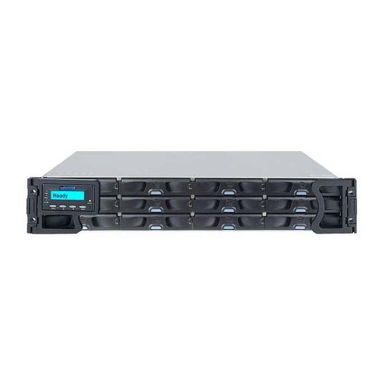
Chapter 1: Introduction supports all advanced RAID technologies and fault tolerance by redundant pairs of other modules. Chassis Overview The S12E RAID storage is housed in a 2U robust chassis that is divided into the front and the rear sections. Key components are respectively accessed through the front and rear panels. -
Page 18: Hard Drive Numbering
EonStor S12E-R1132-4/G1133-2 Installation and Hardware Reference Manual 1.2.2 Hard Drive Numbering The front section of the S12E enclosure houses twelve (12) hard drives in a 4x3 configuration. (See Figure 1-3) When viewed from the front, the drive bays (slots) are numbered 1 to 12 from left to right and then from top to bottom. -
Page 19: Backplane Board
Chapter 1: Introduction Figure 1-5: S12E-G1133-2 Rear View The enclosure rear section accommodates the following components: • RAID controller module(s): The RAID controller module manages all functionalities provided with the subsystem, and all interface connectors are provided on the controller faceplates. -
Page 20: Subsystem Components
EonStor S12E-R1132-4/G1133-2 Installation and Hardware Reference Manual module slot. Feel the contact resistance and use slightly more pressure to ensure the module connectors are correctly mated. If the module comes with ejection levers or retention screws, use them to secure the module. -
Page 21: Drive Trays
Chapter 1: Introduction center; gently press the handles until a click sound is heard. The latches will lock the handles in place. Figure 1-8: Closing the Front Handles 1.3.2 Drive Trays Figure 1-9: Drive Tray Front View The subsystem comes with twelve (12) drive trays designed to accommodate separately purchased standard 1-inch pitch, 3.5-inch SAS/SATA-II (3Gbps) disk drives. -
Page 22: Mux Kit
MUX Kit The MUX kit is a pre-installed item for the drive trays on the dual- controller model: S12E-R1132-4. It enables partner RAID controllers to access individual SATA-II hard drives in a dual-controller configuration. If the SAS hard drives are preferred, there is no need for a MUX kit on each drive tray. -
Page 23: The Raid Controller Module
1.3.4 The RAID Controller Module Figure 1- : RAID Controller Within S12E-R1132-4 Figure 1- : RAID Controller Within S12E-G1133-2 The RAID controller module that came with your subsystem contains a controller board, a BBU module bay, an interface faceplate, and a pre-installed 512MB DIMM module. -
Page 24: 1.3.4.1 Controller Module Interfaces
The S12E system is managed by the RAID controller(s). The controller of S12E-R1132-4 comes with four (4) GbE Ethernet host ports, and that of S12E-G1133-2 comes with two (2) GbE host ports. The subsystem connects to the host through RJ-45 connectors, while... - Page 25 Chapter 1: Introduction Figure 1-15: S12E-G1133-2 Controller Module Interfaces ․ Host ports: S12E-R1132-4 features four (4) Gigabit Ethernet host ports (indicated as CH0 to CH3 in Figure 1-14), while S12E-G1133-2 comes with two (2) Gigabit Ethernet host ports (indicated as CH0 and CH1 in Figure 1-15). These host ports connect the EonStor subsystem to the networked iSCSI initiators through RJ-45 connectors.
- Page 26 EonStor S12E-R1132-4/G1133-2 Installation and Hardware Reference Manual ․ After you upgrade the controller DIMM module to 2GB, use this button to restore firmware defaults. This is to ensure firmware’s embedded 1GB threshold for internal settings, such as the supported no. of logical drives, is upgraded.
-
Page 27: Dimm Module
The controller module comes with a preinstalled 512MB capacity or above DDR RAM DIMM module and the allocable size can reach 2GB. The memory socket is located on the side of the controller board. 1.3.6 Figure 1-16: Pre-installed BBU for S12E-R1132-4 1-13... - Page 28 EonStor S12E-R1132-4/G1133-2 Installation and Hardware Reference Manual Figure 1-17: Optional BBU for S12E-G1133-2 An optional, separately purchased Li-Ion battery backup unit (BBU) module (see Figure 1-16 and Figure 1-17) can sustain cache memory for days during the event of power outage. The battery...
-
Page 29: Power Supply Units
Figure 1-18: PSU Module of S12E-R1132-4 Figure 1-19: PSU Module of S12E-G1133-2 The S12E-R1132-4 is equipped with two (2) 530W PSUs (Figure 1- 18), while S12E-G1133-2 is equipped with two (3) 350W PSUs (Figure 1-19). The redundant, hot-swappable PSU modules are located at the rear of the enclosure. -
Page 30: Cooling Modules
For the PSU specifications, please refer to Appendix A.3. 1.3.8 Cooling Modules Figure 1-20: Cooling Module of S12E-R1132-4 Figure 1-21: Cooling Module of S12E-G1133-2 Both S12E-R1132-4 and S12E-G1133-2 come with redundant cooling modules (See Figure 1-20 and Figure 1-21). Below are the details about the cooling modules: 1-16... -
Page 31: Subsystem Monitoring
Location cooling fans in cooling status of status modules each modules LEDs LEDs module S12E-R1132-4 Refer to On PSU Figure 1-4 faceplates S12E-G1133-2 Refer to On cooling Figure 1-5 module faceplates Intelligent Dual Speed Operation The cooling fans in the cooling module operate with two rotation speeds. -
Page 32: Led Indicators
-- 2 GbE host port LEDs for each port -- 1 LED for the Re store Default functionality • Each BBU (1 LED) • Each cooling module (2 LEDs on S12E-R1132-4; 1 LED on S12E-G1133-2) • Each PSU module (1 LED) 1.4.3 Audible Alarms... -
Page 33: Hot-Swappable Components
1.5.2 Components The following components are hot-swapp able: • Controller module (S12E-R1132-4) • Cooling mo dules (S12E-G1133-2) • BBU(s) • PSUs •... - Page 34 EonStor S12E-R1132-4/G1133-2 Installation and Hardware Reference Manual NOTE: Instructions on how to replace these hot-swappable components are given in Chapter 5. 1-20...
-
Page 35: Chapter 2 Hardware Installation
Chapter 2 Hardware Installation Introduction This chapter provides detailed instructions on how to install the subsystem into the rack, and how to install hard drives, drive trays and optional BBU into the subsystem. Installation into a rack or cabinet should occur before the hard drives or drive trays can be installed into the subsystem. - Page 36 One (1) or two (2) Ethernet cables to the 10/100BasetT management port. Please see Section 4.2 for sample topologies and configuration options. As to the accessory info, please visit Infortrend webpage www.infortrend.com 5. Memory modules: If you wish to replace the pre-installed DDR RAM DIMM module, please refer to Section 5.3.
-
Page 37: Safety Precautions
3Gbps speed using its the jumpers or configuration utility. 10. Rack installation: The enclosure chassis can be installed into a rack cabinet using separately purchased mounting rails, rear- attached brackets, or Infortrend’s rackmount rails. (See Section 2.6) Safety Precautions 2.3.1... - Page 38 EonStor S12E-R1132-4/G1133-2 Installation and Hardware Reference Manual detergent. Please use a slightly moistened paper towel or cloth instead. If it is necessary to transport the subsystem, remove and repackage all disk drives separately using the original foam boxes. The subsystem is intended to be rack-mounted. The following concerns should be heeded when you install the enclosure into a rack cabinet.
- Page 39 Chapter 2: Hardware Installation components. 6. Because hard drives are prone to damage due to shock and vibration during operation, all hard drives should be installed in a rack cabinet prior to powering up. 7. Drives must not be stacked on top of each other without their protective drive trays.
-
Page 40: Static-Free Installation
EonStor S12E-R1132-4/G1133-2 Installation and Hardware Reference Manual kilograms (44 lbs.). Two people will be required to install or relocate the subsystem. 16. Handle system modules by the retention screws, ejection levers, or the module’s metal frame/faceplate only. Avoid touching the PCB boards or connector pins. -
Page 41: Unpacking The Subsystem
Chapter 2: Hardware Installation 3. Install hard drives: Separately purchased SAS or SATA-II hard drives must be individually installed into the drive trays. (See Section 2.7) 4. Install drive trays: After the hard drives have been secured in the drive trays, the drive trays must be installed into the enclosure itself. -
Page 42: Preinstalled Components
EonStor S12E-R1132-4/G1133-2 Installation and Hardware Reference Manual NOTE: Do not rely on the non-definitive, summarized unpacking list shown below -- it is for reference only. A detailed unpacking list can be found in your product shipping package or product CD. -
Page 43: Components To Be Installed
The enclosure is designed to fit into a variety of 19-inch wide rack cabinets or racks. If you would like to purchase the rackmount rail kit from Infortrend, please contact your vendor. See the matching table below to find the suitable rail kit for your subsystem. - Page 44 EonStor S12E-R1132-4/G1133-2 Installation and Hardware Reference Manual Figure 2-3 Rackmount Kit Contents Item Description Quantity Left-side rackmount rail assembly Right-side rackmount rail assembly M5 x 30mm Pan Head screws M5 x 9mm Flat Head screws # 6-32 x 6mm Flat Head screws...
- Page 45 Chapter 2: Hardware Installation Step 3. Secure the left-side and right-side rails to the rack with two (2) M5 flathead screws on the front and the rear rack posts. (See Figure 2-4) Step 4. Attach two (2) M5 cage nuts to both sides of the front rack posts.
-
Page 46: Rackmounting Procedure For S12E-G1133-2
EonStor S12E-R1132-4/G1133-2 Installation and Hardware Reference Manual Figure 2-7: Locations of the Rivets and the Stoppers CAUTION! At least two people are required to install the subsystem. Step 8. There are two (2) screw holes on each side of the chassis ears. - Page 47 Chapter 2: Hardware Installation Figure 2-9 Rackmount Kit Contents Item Description Quantity Left-side front bracket Right-side front bracket Left-side rear bracket Right-side rear bracket Inner brackets M5 x 10mm Truss Head screws M5 x 30mm Pan Head screws #6-32 x 6mm Flat Head screws M5 cage nuts Table 2-2: Rackmount Kit Components Step 2.
- Page 48 EonStor S12E-R1132-4/G1133-2 Installation and Hardware Reference Manual Figure 2-10: Fitting Enclosure Support Brackets Step 3. Determine the position where the subsystem is going to be installed on the rack. Attach four (4) M5 cage nuts to both of the front rack posts and two (2) to both of the rear rack posts.
- Page 49 Chapter 2: Hardware Installation Figure 2-12: Adjusting Support Bracket Length Step 5. Pass two (2) M5 x 10mm Truss Head screws through the middle two (2) screw holes on front and rear sides of the support brackets, and then fasten the screws. There are cage nuts behind the screw holes.
- Page 50 EonStor S12E-R1132-4/G1133-2 Installation and Hardware Reference Manual Figure 2-14: Attaching Inner Brackets to the Chassis Step 7. Slide the enclosure into the rack. When mounting the enclosure into the rack, carefully orient the protruding edges of inner brackets so that they fit into the metal grooves on the support brackets.
-
Page 51: Hard Drive Installation
Drive type: The subsystem is designed to accommodate SAS or SATA-II hard drives. MUX kit: For the dual-controller S12E-R1132-4 subsystem, SAS-to- SATA MUX kits come with the drive trays as default equipments. Only with MUX kits can SATA drives be used in the subsystem. If... -
Page 52: Drive Installation Procedure
EonStor S12E-R1132-4/G1133-2 Installation and Hardware Reference Manual SAS drives are preferred, you have to remove the MUX kits. (For the removal procedure of MUX kits, refer to Section 5.8, step 1-3) The single-controller S12E-G1133-2 subsystem can work with both SAS and SATA hard drives without MUX kits. -
Page 53: Drive Tray Installation
Chapter 2: Hardware Installation without a MUX board are different. Please refer to Figure 2-18. Figure 2-18: Drive Locations with and without the MUX Step 3. Secure the disk drive with four (4) of the supplied 6/32 flat-head screws. Step 4. Once the hard drives are installed into drive trays, install all drive trays into the enclosure. - Page 54 EonStor S12E-R1132-4/G1133-2 Installation and Hardware Reference Manual Figure 2-19: Front View of a Drive Tray whose Bezel Lock in Unlocked Position Step 2. Open the front flap on the drive tray by pushing the release button on the front flap (see Figure 2-20). The front flap will automatically spring open.
-
Page 55: Bbu Installation
The BBU is an optional item for the S12E-G1133-2 and can be ordered separately from your subsystem vendor. You may skip this section if you are using an S12E-R1132-4 redundant-controller subsystem because two (2) BBUs come as pre-installed components. 2.9.1 BBU Warnings and Precautions ․... -
Page 56: Bbu Installation Procedure
EonStor S12E-R1132-4/G1133-2 Installation and Hardware Reference Manual ․ Do not use or leave the BBU near a heat source. Heat can melt the insulation and damage other safety features of the battery cells, possibly causing an acid leak and may result in a fire or explosion. - Page 57 Chapter 2: Hardware Installation Figure 2-25: Installing the BBU Step 3. Secure the BBU to the subsystem by fastening the retention screws on the BBU. (See Figure 2-25) Step 4. The LED should start flashing to indicate that the BBU is being charged.
- Page 58 EonStor S12E-R1132-4/G1133-2 Installation and Hardware Reference Manual This page is intentionally left blank. 2-24...
-
Page 59: Chapter 3 Subsystem Monitoring
Chapter 3 Subsystem Monitoring Overview The S12E subsystem is equipped with a variety of self-monitoring features that help keep system managers informed of the subsystem operational statuses. These monitoring features provide vital feedback to help you maintain the operational integrity of the subsystem. -
Page 60: Status-Indicating Leds
EonStor S12E-R1132-4/G1133-2 Installation and Hardware Reference Manual ․ Inter-Integrated Circuit (I C): An I C bus connects to temperature sensors and presence detection circuits that reside on PSUs, backplane, cooling modules, RAID controller board, and the BBU. If any problem is detected, it will be reported in the ways stated above. -
Page 61: Drive Tray Leds
Chapter 3: Subsystem Monitoring the host/drive channels. indicates that component failure/status event has occurred. ATTEN (Attention) OFF indicates that the subsystem and all its components are operating correctly. Table 3-1: LCD Panel LED Definitions NOTE: During the power-on process, the ATTEN LED will light up steadily. -
Page 62: Controller Module Leds
Controller Module LEDs The controller faceplate is shown below. There are seventeen (17) LEDs of different types on the controller of S12E-R1132-4 (See Figure 3-3) and thirteen (13) on the controller of S12E-G1133-4 (See Figure 3-4). Their respective meanings are described in the following sub-sections. -
Page 63: System Status Leds
Chapter 3: Subsystem Monitoring Figure 3-4: Controller LEDs on S12E-G1133-2 3.2.3.1 System Status LEDs The controller status LEDs are numbered from 1 to 6 and located on the controller’s rear-facing faceplate. (See Figure 3-3 and Figure 3-4) The definitions are shown in Table 3-3. Name Color Status... -
Page 64: Restore Default Led
EonStor S12E-R1132-4/G1133-2 Installation and Hardware Reference Manual range). - Battery is not present. OFF indicates that the cache is clean, and that the battery backup unit is capable of sustaining memory in case of power loss. This signal is local to each controller. -
Page 65: Bbu Module Led
LAN Activity Green transmission. Table 3-5: 10/100BaseT Management Port LED Definitions 3.2.4 BBU Module LED The BBU module has an LED on its faceplate. Its location is shown in Figure 3-7 and Figure 3-8. Figure 3-7: BBU LEDs on S12E-R1132-4... - Page 66 EonStor S12E-R1132-4/G1133-2 Installation and Hardware Reference Manual Figure 3-8: BBU LED on S12E-G1133-2 The function is the same as the similar LED on the controller module. The LED is off when the BBU is functioning normally and is able to sustain the cache memory.
-
Page 67: Psu Leds
The PSU is not turned on and the power cord is disconnected. Table 3-6: PSU Module LED Definitions 3.2.6 Cooling Module LEDs On S12E-R1132-4, each cooling module has two (2) amber LEDs located on the PSU canister. Each LED corresponds to an individual... - Page 68 EonStor S12E-R1132-4/G1133-2 Installation and Hardware Reference Manual cooling fan. (See Figure 3-11) On S12E-G1133-2, each cooling module has one (1) red LED located on the right upper corner of the module itself (See Figure 3-12) Please refer to the cooling module LED definitions shown in Table 3-7.
-
Page 69: Audible Alarm
Chapter 3: Subsystem Monitoring Color Status ON: The cooling fan has failed. Static Amber (S12E-R1132-4)/ OFF: The cooling fan operates normally. Static Red (S12E- G1133-2) Table 3-7: Cooling Module LED Definitions Audible Alarm 3.3.1 Overview Different controller environmental and operational parameters (such as temperature and voltage) have been assigned a range of values between which they can fluctuate. - Page 70 EonStor S12E-R1132-4/G1133-2 Installation and Hardware Reference Manual • Sensors and presence detection circuits NOTE: When temperature exceeds a preset threshold, the controller’s charger circuits will stop charging. You will then receive a message that reads “Thermal Shutdown/Enter Sleep Mode.” When the temperature falls back within normal range, the battery will resume charging.
-
Page 71: Chapter 4 Subsystem Connection And Operation
Chapter 4 Subsystem Connection and Operation Connection Overview 4.1.1 Cabling Following are the requirements on the type of cables used to connect the subsystem’s iSCSI host ports: ․ Ethernet cables are user-supplied. Cat5e shielded STP type network cables or better performance types (important for meeting the requirements imposed by emission standards). -
Page 72: Network Topologies
Ethernet. Data flow and access management should therefore be implemented to avoid access contention. Infortrend’s EonPath ™ software can be implemented in order to access a RAID volume through an alternate data link in the event of cabling failure. - Page 73 2 or more fault-tolerant paths A GbE network switch iSCSI ports on a RAID controller; the one with 4 ports signifying the controller on S12E-R1132-4, and the one with 2 ports signifying the controller on S12E-G1133-2 A logical drive consisting of multiple physical drives A physical data link A logical association, e.g., that between a logical...
-
Page 74: Sample Topology - High Availability Ip San With Redundant Raid Controllers
EonStor S12E-R1132-4/G1133-2 Installation and Hardware Reference Manual Component Description RAID system: iSCSI RAID managed by a single controller, with 2 S12E-G1133-2 host ports GbE cables GbE network cables iSCSI initiators, better be PCI-E TOE cards RAID configuration 2 logical drives (each has 6 member drives) - Page 75 Chapter 4: Subsystem Connection and Operation GbE switch GbE networking device used to connect network components Software EonPath to manage the fault-tolerant paths with failover/failback and load balance capabilities. Use EonPath multi-pathing software so that your operating system can identify alternate paths to the same logical drive.
-
Page 76: Sample Topology - High Availability Ip San With Multiple Connections Per Session (Firmware Revision 3.64)
EonStor S12E-R1132-4/G1133-2 Installation and Hardware Reference Manual NOTE: In the event of single controller failure, a logical drive is accessed through the host IDs managed by the alternate RAID controller. Host IDs and port IPs do not fail-over to the surviving controller. Therefore, the EonPath multi- pathing driver is necessary for path redundancy and controller failover. - Page 77 Chapter 4: Subsystem Connection and Operation Figure 4-3: High Availability IP SAN with Multiple Connections per Session NOTE: In the event of single controller failure, a logical drive is accessed through the host IDs managed by the alternate RAID controller. Host IDs and port IPs do not fail-over to the surviving controller.
-
Page 78: Expansion Links
8470 4.3.1 Expansion Configuration 4.3.1.1 Dual-controller RAID to dual-controller JBOD The redundant-controller model, S12E-R1132-4, can connect up to 3 JBODs. Expansion Link Considerations: ․ A 120cm cable may be necessary as an expansion link if you route the fault-tolerant cables from opposite directions. Routing cables... -
Page 79: Single-Controller Raid To Single-Controller Jbod
Chapter 4: Subsystem Connection and Operation Figure 4-4: Connecting Dual-controller JBODs with S12E-R1132-4 4.3.1.2 Single-controller RAID to single-controller JBOD The single-controller model, S12E-G1133-2, can connect up to 4 JBODs. Figure 4-5: Connecting Single-controller JBODs with S12E-G1133-2... -
Page 80: Enclosure Id Settings
EonStor S12E-R1132-4/G1133-2 Installation and Hardware Reference Manual 4.3.2 Enclosure ID Settings There is a rotary ID switch on every expansion enclosure that is manually configured using a flat blade screwdriver. The configurable IDs start from 1 to 6. Usually the numbering starts from the one closest to the managing RAID enclosure. -
Page 81: Power On
-- SAS and SATA drives come with different capacities. Do not include drives of different capacities in a logical drive. Otherwise, some part of the larger drives’ capacity will be wasted. Infortrend firmware always uses the maximum capacity of the smallest drive as the standard capacity of all member drives when composing a logical drive. -
Page 82: Power On Procedure
EonStor S12E-R1132-4/G1133-2 Installation and Hardware Reference Manual BBU Modules – If BBU module is used, make sure that it has been installed correctly. Hard Drives – Hard drives have been correctly installed on the drive trays. Drive Trays – ALL the drive trays, whether or not they have a hard drive, have been installed into the subsystem. -
Page 83: Power On Status Check
Chapter 4: Subsystem Connection and Operation Figure 4-8: Power Sockets and Power Switches on S12E-R1132-4 Figure 4-9: Power Sockets and Power Switches on S12E-G1133-2 CAUTION! Although the PSUs are redundant and a single PSU can provide sufficient power to the system, it is advisable to turn on both power supplies. -
Page 84: Power Off Procedure
EonStor S12E-R1132-4/G1133-2 Installation and Hardware Reference Manual drives. The Drive Busy LEDs should also start blinking, indicating that system is attempting to access hard drives. 3. LEDs on LCD keypad panel: The blue LED on the LCD keypad panel should illuminate after the system initialization process, indicating that system status is ready. - Page 85 Chapter 4: Subsystem Connection and Operation Locate the Cache_Dirty LED on the back of controller module to check if there is data cached in the memory. Use the “Shutdown Controller” function to flush all cached data. This prepares the RAID subsystem to be safely powered down. Step 3.
- Page 86 EonStor S12E-R1132-4/G1133-2 Installation and Hardware Reference Manual This page is intentionally left blank. 4-16...
-
Page 87: Overview
Chapter 5 Subsystem Maintenance Upgrading 5.1. Overview 5.1.1 Maintenance Constant monitoring and maintenance of your S12E-R1132- 4/G1133-2 subsystem will minimize system downtime and preserve the working integrity of the system for a longer period of time. If any of the system components fails, they must be replaced as soon as possible. -
Page 88: Replacing A Controller Module
EonStor S12E-R1132-4/G1133-2 Installation and Hardware Reference Manual including the PSU modules (along with the cooling modules within), BBU, and drive trays, are hot-swappable and can be replaced while the subsystem is still in operation. ․ Qualified engineers who are familiar with the subsystem should be the only ones who make component replacements. -
Page 89: Notes On Controller Maintenance
Chapter 5: Subsystem Maintenance and Upgrading ․ DIMM Module The DIMM module can be replaced when a DIMM module fails or if a larger capacity DIMM is required. ․ If the BBU has lost its ability to hold electric charge, replace it with a certified module. With the new BBU that comes with ASIC400 models, an EEPROM is implemented and that system administrators will be notified by... - Page 90 EonStor S12E-R1132-4/G1133-2 Installation and Hardware Reference Manual Disconnect all cables from the failed controller module. Step 2. These may include the Ethernet cables connected to the network, and any cable connected to the RS-232C audio jack connector. Remove the screws that secure the ejection levers to Step 3.
- Page 91 Chapter 5: Subsystem Maintenance and Upgrading Figure 5-2: Removing Controller Install the replacement controller. Make sure the Step 5. ejection levers are at its lowest position. Align the controller module with the controller module bay. Gently slide the controller module in. Carefully push the controller until you feel the contact resistance when the back-end connectors are engaging the backplane.
-
Page 92: Replacing A Controller Module On S12E- R1132-4
EonStor S12E-R1132-4/G1133-2 Installation and Hardware Reference Manual Figure 5-4: Using the Ejection Levers to Secure Controller Secure the controller module to the chassis. Fasten Step 7. the two (2) screws that secure the ejection levers. Re-attach all cables that were removed. These include Step 8. - Page 93 Chapter 5: Subsystem Maintenance and Upgrading Figure 5-5: Loosening the Controller Captive Screws Remove the failed controller by simultaneously pulling Step 4. the captive screws on both sides. Place the controller module on the clean, static-free work pad or container previously prepared.
-
Page 94: Replacing Or Upgrading Memory Modules
EonStor S12E-R1132-4/G1133-2 Installation and Hardware Reference Manual WARNING! ․ Unnecessary tampering with the controller module can cause damage. Remove the controller ONLY when it is absolutely necessary. ․ When you remove a controller module from the chassis, all anti-static preventative measures should be strictly adhered to. - Page 95 Chapter 5: Subsystem Maintenance and Upgrading De f a u lt Va lu e Feature <1GB DIMM > 1GB DIMM 64-bit LBA Support (>2TB) Number of LDs 32 (Max.) 16 (Max.) 16 (Max.) Number of LVs 8 (Max.) Number of Partitions per LD 16 (Max.) 64 (Max.) 8 (32 Max.)
- Page 96 EonStor S12E-R1132-4/G1133-2 Installation and Hardware Reference Manual Work Procedures: Upgrade memory in a single-controller system (512MB to Case 1: 1/2GB) 1-1. Shut down host computer(s). 1-2. Power OFF the RAID system. 1-3. Remove the RAID controller and replace its memory with a 1GB or 2GB DIMM.
-
Page 97: Selecting The Memory Modules
DIMM modules: ․ Purchasing a DIMM module: To avoid the compatibility issues, it is recommended to contact Infortrend or your subsystem vendor for an updated list of compatible DIMM modules. We provide tested modules from reliable vendors with reliable chips. -
Page 98: Dimm Module Installation Procedure
EonStor S12E-R1132-4/G1133-2 Installation and Hardware Reference Manual 5.3.3 DIMM Module Installation Procedure To replace the DIMM module: WARNING! The pre-installed modules must be removed prior to installing new modules. Do this with care. Sensitive components can be damaged during the process. -
Page 99: Replacing A Faulty Bbu
Chapter 5: Subsystem Maintenance and Upgrading Figure -9: Removing a DIMM Module on S12E-G1133-2 Step 5. Insert the replacement module into the DIMM socket. Make sure the white clips of the DIMM socket are in the open positions. Align the DIMM module with the DIMM socket by checking its “keyed”... -
Page 100: Bbu Warnings And Precautions
EonStor S12E-R1132-4/G1133-2 Installation and Hardware Reference Manual A BBU failure can result from the following: ․ A BBU has lost its ability to hold electrical charge. This may be the case after the battery cells have been recharged for many times regardless of how long the module has been used. -
Page 101: Bbu Replacement Procedure
If this is discovered when you first use the BBU, return it to Infortrend or your subsystem vendor. 5.4.3 BBU Replacement Procedure... - Page 102 EonStor S12E-R1132-4/G1133-2 Installation and Hardware Reference Manual Install the replacement BBU. Align the BBU with the Step 2. module bay, and then gently push the BBU into the bay. When you feel the contact resistance, use sl ightly more force for the back-end connector to mate with corresponding connector on the backplane.
-
Page 103: Replacing A Faulty Psu
Chapter 5: Subsystem Maintenance and Upgrading Figure 5-14: BBU LEDs on S12E-R1132-4 Figure 5-15: BBU LED on S12E-G1133-2 NOTE: ․ A new or replaced BBU takes at most twelve (12) hours to charge to its full capacity. Reset the subsystem whenever a BBU is replaced or added in order for the new BBU to take effect. -
Page 104: Psu Module Replacement Procedure
․ PSU canister: The PSU module is housed in a robust steel canister. In S12E-R1132-4, the power supply converter unit is in the front section of the canister and the cooling fan module in the rear section. In S12E-G1133-2, the power supply... - Page 105 Loosen the PSU retention screw that secures the Step 3. extraction handle to the chassis. (See Figure 5-18 and Figure 5-19) Figure 5-18: Loosening the PSU Retention Screw on S12E-R1132-4 Figure 5-19: Removing the PSU Retention Screw on S12E-G1133-2 5-19...
- Page 106 EonStor S12E-R1132-4/G1133-2 Installation and Hardware Reference Manual For S12E-R1132-4, remove the PSU by grabbing the Step 4. extraction handle and pulling the handle upwards. For S12E-G1133-2, remove the PSU by pushing the handle downwards. The extraction handle should gracefully disconnect the PSU from the backplane connectors.
-
Page 107: Cooling Module Maintenance
5.6.1 Notes on Cooling Module Maintenance ․ Redundant cooling modules: S12E-R1132-4 is equipped with four (4) cooling fans, two (2) within each cooling module, while S12E-G1133-2 is equipped with three (3) cooling fans, one (1) within each cooling module. These cooling modules control the operating temperature within the chassis;... -
Page 108: Cooling Module Replacement Procedure
Please refer to Section 5.5.2, Step 1-4 for how to remove a PSU. Step 2. Use a small-size Phillips screwdriver to remove the six securing screws of cooling modules from the top. (See Figure 5-22) Figure 5-22: Removing the Cooling Module on S12E-R1132-4 5-22... - Page 109 Chapter 5: Subsystem Maintenance and Upgrading Remove the retention screw on the side of PSU canister Step 3. and push the release tab forward to disengage the cooling module. Step 4. Remove the cooling fan module by the following steps: Step 4-1.
-
Page 110: Replacing A Hard Drive
EonStor S12E-R1132-4/G1133-2 Installation and Hardware Reference Manual Install the replacement module by aligning it with the Step 3. module bay and gently pushing it in. Push the cooling module until it reaches the end of the module bay. Use slightly more force when feeling the contact resistance to engage the back-end connectors. - Page 111 Chapter 5: Subsystem Maintenance and Upgrading WARNING! Hard drives are fragile; therefore, always handle them with extreme care. ․ Do not drop the hard drive. ․ Always be slow, gentle, and careful when handling a hard drive. ․ Handle a hard drive only by the edges of its metal cover, and avoid touching its circuits part and interface connectors.
-
Page 112: Replacing Amux Kit
EonStor S12E-R1132-4/G1133-2 Installation and Hardware Reference Manual Figure -25: Opening the Drive Tray Front Bezel Remove the drive tray by pulling it one inch away Step 4. from the drive bay. Wait for at least 30 seconds for the disk drive to spin down (if the disk drive is removed not... - Page 113 Chapter 5: Subsystem Maintenance and Upgrading Remove the hard drive from the drive tray, after the Step 2. drive tray has been removed from the subsystem. (See Section 5.7.2, step 5) Turn the drive tray over and remove the two (2) Step 3.
- Page 114 EonStor S12E-R1132-4/G1133-2 Installation and Hardware Reference Manual This page is intentionally left blank. 5-28...
-
Page 115: Appendix A Specifications
Without Forearm With Forearm Handles Handles (Not including rear-end protrusions) Height 88mm 88mm Width 446mm 482mm Depth 498mm (S12E-R1132-4) 516mm (S12E-R1132-4) 490mm (S12E-G1133-2) 505mm (S12E-G1133-2) Package dimensions: 390H x 575W x 780D mm (S12E-R1132-4) 390H x 570W x 780D mm (S12E-G1133-2) - Page 116 EonStor S12E-R1132-4/G1133-2 Installation and Hardware Reference Manual System Weight 18.7 kg (S12E-R1132-4) 23.5 kg (S12E-G1133-2) Gross 25.9kg (S12E-R1132-4) 25 kg (S12E-G1133-2) Shock Half-sine Operating: 5G peak, 11ms half-sine Non-operating: 15G, 11ms, half-sine Vibration Operating 0.5oct/min, 5 to 500Hz, sinewave, 0.2G Non- 0.5oct/min, 5 to 500Hz, sinewave, 1.0G...
-
Page 117: Functional Specifications
Memory Yes; with transparent reset of non-responsive Drive Hot-swap drives Controller Hot- S12E-R1132-4 only swap capability Architectural Specifications PowerPC RISC processor DIMM Slot Female, 180 degree Memory Module ECC DIMM Supported ASIC Infortrend 64-bit chipset (ASIC400) Flash ROM 64Mbit (8MB) -
Page 118: Power Supply Specifications
EonStor S12E-R1132-4/G1133-2 Installation and Hardware Reference Manual 32KB with RTC (with embedded RAIDWatch NVRAM utility) Hardware XOR For event messages with time record and task Real-time Clock scheduling Power Supply Specifications Specifications 530W with active PFC (S12E-R1132-4) Nominal Power 350W with active PFC (S12E-G1133-2) S12E-R1132-4 12.0V: 43A (Max.) -
Page 119: Raid Management
Appendix A: Specifications S12E-R1132-4 13.2 / 7.68W max Input power S12E-G1133-2 9 / 3.12W max. DC 12V Rated Voltage S12E-R1132-4 Operating: -10 to +70ºC Storage: -30 to +70ºC Temperature S12E-G1133-2 Operating: -10 to +60ºC Storage: -30 to +70ºC RAID Management Specifications •... -
Page 120: Fault Tolerance Management
EonStor S12E-R1132-4/G1133-2 Installation and Hardware Reference Manual Fault Tolerance Management Specifications Yes, with user-configurable detect-only, clone and Drive S.M.A.R.T Support replace, and perpetual clone functions. Yes, life expectancy and Battery Back-up Option charge level aware Sensors and module presence detection through an I... -
Page 121: Gbe Ethernet Port Pinouts (Iscsi Host Ports)
Appendix B Pinouts GbE Ethernet Port Pinouts (iSCSI Host Ports) Figure B-1: GbE Ethernet Port Automatic MDI/MDI-X Crossover: Crossover can be implemented internally at hub or switch or externally through twisted pair media. Pin Name Color Match BI_DA+ Orange BI_DA- Orange/white BI_DB+ Green... -
Page 122: 10/100B Aset Ethernet Port Pinouts (Management Port
EonStor S12E-R1132-4/G1133-2 Installation and Hardware Reference Manual 10/100BaseT Ethernet Port Pinouts (Management Port) Figure B-2: 10/100BaseT Ethernet Port Pin Name Color Match LAN_TXP Orange LAN_TXN Orange/white LAN_RXP Green Blue/white Blue LAN_RXN Green/white Brown Brown/white Table B-2: 10/100BaseT Ethernet Port Pinouts STP Ethernet Cable (Optional Accessory) This shielded twisted pair cable is an optional accessory item. -
Page 123: Com1 Serial Port Cable: Db9 And Audio Jack Pinouts
Appendix C: Pinouts metal shield – braided wire – metal shield Figure B-3: STP Ethernet Cable Pinouts COM1 Serial Port Cable: DB9 and Audio Jack Pinouts The COM 1 Cable is used to connect a PC running terminal emulation program. Figure B-4: COM1 Serial Port Cable... -
Page 124: Com2 Serial Port Cable To Ups: Db9 And Audio Jack Y-Cable Pinouts
EonStor S12E-R1132-4/G1133-2 Installation and Hardware Reference Manual P2 Pin Number Pin Name P1 Pin Number Pin Name DTR (Shorted) DSR (Shorted) RTS (Shorted) CTS (Shorted) Table B-3: COM1 Serial Port Cable Pinout Definitions COM2 Serial Port Cable to UPS: DB9 and... -
Page 125: Sas Expansion Port Pinouts
Appendix C: Pinouts CN1 Pin Number Pin Name Table B-4: COM2 Adapter Cable CN1 and CN2 Pinout Definitions SAS Expansion Port Pinouts The Mini SAS host ports comply with SFF-8088 specification. Figure B-6: Mini SAS SFF-8088 Connector Description Description RX0+ TX0+ RX0- TX0-... -
Page 126: Ift-9011 Null Modem
EonStor S12E-R1132-4/G1133-2 Installation and Hardware Reference Manual RX3- TX3- Table B-5: SAS Expansion Port Pinout Definitions IFT-9011 Null Modem A null modem is used for wire-swap and is necessary for connecting COM1 CN2 to a PC serial port. Figure B-7: Null Modem Pinouts...
Need help?
Do you have a question about the EonStor S12E-R1132-4 and is the answer not in the manual?
Questions and answers