
Related Manuals for Infortrend EonStor S12S-G1033


Summary of Contents for Infortrend EonStor S12S-G1033
- Page 1 Installation and Hardware Reference Manual ® EonStor S12S-G1033 S12S-G1033P 2U Profile SAS-to-SAS/SATA RAID Subsystem Version 1.4 (November, 2011)
-
Page 2: Contact Information
EonStor S12S-G1033/P Installation and Hardware Reference Manual Contact Information Customer Support Contact your system vendor or visit the following support sites. EonStor DS Support ESVA Support EonNAS Support Headquarters Infortrend Technology, Inc. (Taiwan) 8F, No. 102, Sec. 3, Jhongshan Rd., Jhonghe Dist., New Taipei City 235,... - Page 3 Infortrend, the Infortrend logo, SANWatch, ESVA, EonStor, Trademarks EonStor DS, EonNAS, and EonPath are registered trademarks of Infortrend Technology, Inc. Other names prefixed with “IFT” and “ES” are trademarks of Infortrend Technology, Inc. Windows is a registered trademark of Microsoft Corporation.
-
Page 4: Warnings And Certifications
EonStor S12S-G1033/P Installation and Hardware Reference Manual Warnings and Certifications Restricted Access Location: This equipment is intended to be installed in a RESTRICTED ACCESS LOCATION only. Electric Shock Warning! To Prevent Electric Shock: Access to this equipment is granted only to trained operators and... - Page 5 EonStor S12S-G1033/P Installation and Hardware Reference Manual interference, and 2) this device must accept any interference received, including interference that may cause undesired operation. Warning! A shielded power cord is required in order to meet FCC emission limits and also to prevent interference with nearby radio and television reception.
- Page 6 EonStor S12S-G1033/P Installation and Hardware Reference Manual This device is in conformity with UL standards for safety. This device is in conformity with Russia GOST-R standards for safety. Инструкция по безопасности Модель: FC to SAS/SATA 2U/12Bay RAID Subsystem, Models ESS12F- R1432xxxxxx, ESS12F-G1433xxxx, where “x”...
- Page 7 European directive, RoHS (2002/95/EC), on or before the specific dates set forth in those applicable laws and regulations. Infortrend is applying its own internal efforts and expertise and is working closely with customers and suppliers to achieve compliance while maintaining an uninterrupted supply of quality products.
-
Page 8: Table Of Contents
EonStor S12S-G1033/P Installation and Hardware Reference Manual Table of Contents ....................II ONTACT NFORMATION ........................III POYRIGHT ................IV ARNINGS AND ERTIFICATIONS ....................X AFETY RECAUTIONS Precautions and Instructions....................x ESD Precautions.........................x ....................XI BOUT ANUAL Revision History .........................xi Who should read this manual?...................xi Related Documentation .....................xi... - Page 9 EonStor S12S-G1033/P Installation and Hardware Reference Manual 3.1.1 Host Link Cables ..................3-1 3.1.2 Other Concerns..................3-2 ..................3-4 AMPLE OPOLOGY ..................3-5 XPANSION INKS CHAPTER 4 ....................4-1 OWER 4.1.1 Check List ....................4-1 4.1.2 Power On Procedure .................. 4-1 4.1.3...
-
Page 10: Safety Precautions
EonStor S12S-G1033/P Installation and Hardware Reference Manual Safety Precautions Precautions and Instructions Provide a soft, clean surface to place your subsystem on before working on it. Servicing on a rough surface may damage the exterior of the chassis. ... -
Page 11: Esd Precautions
EonStor S12S-G1033/P Installation and Hardware Reference Manual ESD Precautions Observe all conventional anti-ESD methods while handling system modules. The use of a grounded wrist strap and an anti-static work pad are recommended. Avoid dust and debris in your work area. -
Page 12: Related Documentation
Naming From this point on and throughout the rest of this manual, the EonStor series may frequently be referred to as simply the “subsystem” or the “system.” The EonStor S12S-G1033 subsystem name is abbreviated as S12S-G1033. Lists Bulleted Lists: Bulleted lists are statements of non-sequential facts. -
Page 13: Software And Firmware Updates
These messages inform readers of essential but non-critical information. They should be read carefully as any directions or instructions contained therein can help you avoid making mistakes. Software and Firmware Updates Please contact your system vendor, visit Infortrend’s FTP site (ftp.infortrend.com), Room website (http://viproom.infortrend.com.tw/) for the latest software or firmware... -
Page 14: Product Overview
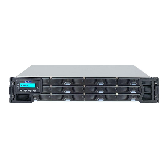
Chapter 1 Introduction Product Overview This hardware manual briefly introduces the EonStor S12S-G1033 SAS to Serial Attached SCSI (SAS) RAID subsystem. The 12-bay model comes with two (2) SAS host channels and supports twelve (12) hot-swappable SAS or SATA II hard drives in an 2U chassis. The core of the subsystem is the RAID controller module boosted by the ASIC400 RAID engine. -
Page 15: Chassis Overview
EonStor S12S -G1033/P Installation and Hardware Reference Manual NOTE: On receiving and unpacking your subsystem, please check the package contents against the included Unpacking List. If any module is missing, please contact your subsystem vendor immediately. Chassis Overview The subsystem chassis is an enhanced 2U storage chassis divided into front and rear sections, which are respectively accessed through front and rear panels. -
Page 16: Rear Panel Overview
Chapter 1: Introduction ˙ LCD keypad panel: The LCD panel is mounted on the left-side forearm handle. The panel comes with status LEDs, function keys, and a mute button. (See Section 1.3.1) 1.2.2 Rear Panel Overview The enclosure rear view is shown below. The rear panel provides access to all enclosure components. -
Page 17: Physical Dimensions
EonStor S12S -G1033/P Installation and Hardware Reference Manual WARNING! Accessing the backplane board may lead to fatal damage of the RAID subsystem. Also, a physical contact with the backplane may cause electrical hazards. For example, short-circuiting may occur if you accidentally touch the backplane with a screwdriver. -
Page 18: Drive Tray
Chapter 1: Introduction configuration and monitoring options. After the subsystem is powered up, the initial screen displays the subsystem model name. A different name can be manually assigned to the subsystem or to different RAID arrays. This enables easier identification in a topology consisting of numerous arrays. -
Page 19: Raid Controller Module
EonStor S12S -G1033/P Installation and Hardware Reference Manual drive swapping. There are screw holes on the sides of the drive tray for securing hard drives to the drive tray. WARNING! Be careful not to warp, twist, or contort the drive tray in any way (e.g., by dropping it or resting heavy objects on it). -
Page 20: Controller Module Interfaces
(1) host link cable. ˙ SAS Expansion Port: The SAS Exp. port is meant to connect to expansion enclosures, i.e., Infortrend’s S12S-J1000-G. The subsystem can connect to the maximum of four (4) expansion enclosures. For the expansion connection, you have to separately purchase SFF-8088 to SFF-8470 SAS cable. - Page 21 EonStor S12S -G1033/P Installation and Hardware Reference Manual Press and hold the button down while powering on the subsystem will restore firmware default settings. CAUTION! The Restore NVRAM Default push button is a function that carries some risks. Firmware restoration will not affect the existing logical drive configurations;...
-
Page 22: Dimm Module
Chapter 1: Introduction How to use the button? After the subsystem is powered down, you can use a straightened paper clip to press the button. Press and hold the button down, power on the subsystem, and wait for the associated LED and the subsystem Ready LED to light up. -
Page 23: Psus
EonStor S12S -G1033/P Installation and Hardware Reference Manual 1.3.5 PSUs Figure 1-11: PSU Canister The subsystem is equipped with two (2) redundant, hot-swappable, 350W PSUs, which are located at the enclosure’s rear section. (See Figure 1-3) The PSU is permanently mounted into a 2U canister especially designed to contain both the PSU and a cooling module. -
Page 24: Enclosure Monitoring
Chapter 1: Introduction The enclosure is equipped with three (3) redundant, single-fan, cooling modules. (See the figure above) The LED on each canister indicates the cooling fan’s operating status. Intelligent Dual Speed Operation The cooling fans in the cooling modules operate with two rotation speeds. -
Page 25: Led Indicators
EonStor S12S -G1033/P Installation and Hardware Reference Manual will be reported in various ways, such as through the embedded firmware utility or SANWatch Enclosure View. 1.4.2 LED Indicators The following active components come with LEDs to indicate the status of individual components. Please refer to Chapter 4 for more information on System Monitoring. -
Page 26: Hot-Swappable Components
Chapter 1: Introduction Event notification messages indicate the completion or status of array configuration tasks and are always accompanied by two (2) or three (3) successive and prolonged beeps. WARNING! Failing to respond when an audible alarm is heard can lead to permanent damage of the enclosure components. - Page 27 EonStor S12S -G1033/P Installation and Hardware Reference Manual ˙ Power supplies ˙ Hard disk drives ˙ Battery modules NOTE: Instructions on how to replace these hot-swappable components are given in Chapter 5. 1-14...
-
Page 28: Introduction
Chapter 2 Hardware Installation Introduction This chapter provides detailed instructions on how to install the subsystem into the rack, and how to install hard drives and optional BBU into the subsystem. Installation into a rack or cabinet should occur before the hard drives or drive trays can be installed into the subsystem. -
Page 29: Safety Precautions
6. BBU: If you wish to install the optional BBU, do it before you power on the subsystem. (See Section 2.9) 7. Rack installation: The enclosure chassis can be installed into a rack cabinet using separately purchased rackmount brackets, or Infortrend’s IFT-9272CSlider28 and IFT-9272CSlider36 brackets. (See Section 2.6) Safety Precautions 2.3.1 Precautions and Instructions 1. - Page 30 Chapter 2: Hardware Installation obstructed. Ensure proper circulation is available at your installation site and heated air exhausted from the chassis is brought away. d. The rack cabinet into which this enclosure is installed must support over-current protection and must not be overloaded by the modules installed.
-
Page 31: Static-Free Installation
EonStor S12S -G1033/P Installation and Hardware Reference Manual cables so that power cords are not resting against data cables. 11. If the enclosure is not used for a long time, disconnect it from mains to avoid transient over-voltage. 12. Never open the enclosure chassis. For safety reasons, only qualified service personnel should open the equipment. -
Page 32: Preparation
Chapter 2: Hardware Installation connector pins. 2.3.3 Preparation ˙ Make sure you are aware of the related positions of each plug-in module and interface connector. ˙ Cables must be handled with care and must not be bent. To prevent emission interference within a rack system and accidental cable disconnection, the routing path must be carefully planned. -
Page 33: Unpacking The Subsystem
EonStor S12S -G1033/P Installation and Hardware Reference Manual Figure : Installation Flowchart Unpacking the Subsystem Compare the Unpacking List against the actual package contents to confirm that all required materials have been received. Carefully check the items contained in each box before proceeding with installation. -
Page 34: Preinstalled Components
Chapter 2: Hardware Installation 2.5.1 Preinstalled Components The following are pre-installed components: ˙ 1 - LCD keypad panel ˙ 2 - Forearm handles ˙ 1 - Backplane board ˙ 1 - Controller module ˙ 1- DDR RAM DIMM module (in the controller module) ˙... - Page 35 EonStor S12S -G1033/P Installation and Hardware Reference Manual Figure 2-2 Rackmount Kit Contents Item Description Quantity Inner brackets Right-side front bracket Left-side front bracket Right-side rear bracket Left-side rear bracket M5 x 10mm Truss Head screws M5 x 30mm Pan Head screws #6-32 x 6mm Flat Head screws M5 clip nuts Table 2-1: Rackmount Kit Components...
- Page 36 Chapter 2: Hardware Installation Figure 2-3: Fitting Enclosure Support Brackets Step 3. Determine the position where the subsystem is going to be installed on the rack. Attach four (4) M5 clip nuts to each side of the front rack posts and two (2) to each side of the rear rack posts.
- Page 37 EonStor S12S -G1033/P Installation and Hardware Reference Manual Figure 2-5: Adjusting Support Bracket Length Step 5. Pass two (2) M5 x 10mm Truss Head screws through the middle two (2) screw holes on the front side of the support brackets and the middle two clip nuts on the front rack posts, and then fasten the screws.
- Page 38 Chapter 2: Hardware Installation Figure 2-7: Attaching Inner Brackets to the Chassis Step 7. Slide the enclosure into the rack. When mounting the enclosure into the rack, carefully orient the protruding edges of inner brackets so that they fit into the metal grooves on the support brackets.
-
Page 39: Hard Drive Installation
EonStor S12S -G1033/P Installation and Hardware Reference Manual Step 8. There are two (2) screw holes on each side of the chassis ears. To secure the subsystem to the rack, fasten two (2) M5 x 30mm Pan Head screws through the holes. (See the figure below) Figure 2-9: Securing the Subsystem Hard Drive Installation... -
Page 40: Drive Installation
Chapter 2: Hardware Installation WARNING! 1. Handle hard drives with extreme care. Hard drives are very delicate. Dropping a drive onto a hard surface (even over a short distance) and hitting or touching the circuits on the drives with your tools may damage the hard drives. 2. - Page 41 EonStor S12S -G1033/P Installation and Hardware Reference Manual trays are ready to be installed into the subsystem. WARNING! All drive trays must be installed into the enclosure even if they do not contain hard drives. If any drive bays are left empty, the ventilation required for cooling will not be normalized and the subsystem will overheat.
- Page 42 Chapter 2: Hardware Installation Figure 2- : Installing a Drive Tray CAUTION! Slamming the drive tray into the chassis can damage the back-end connector. Step 4. Close the front flap of the drive tray. Close the front flap properly so that the connector at the back of the hard drive can be firmly connected to the corresponding connector on the backplane board.
-
Page 43: Optional Battery Module Installation
EonStor S12S -G1033/P Installation and Hardware Reference Manual Figure 2- : Drive Tray Lock Rotation Optional Battery Module Installation The BBU can sustain cache memory in the event of a power failure or in the extremely unlikely event of failing both PSUs. The use of a BBU is highly recommended in order to avoid data inconsistency. -
Page 44: Installation Procedure
If this is discovered when you first use the BBU, return it to Infortrend or your system vendor. 2.9.2 Installation Procedure To install a BBU into the controller module, please follow these steps: Step 1. - Page 45 EonStor S12S -G1033/P Installation and Hardware Reference Manual Figure 2-18: BBU LED NOTE: A new or replaced BBU takes at least 12 hours to charge to its full capacity. You may check the BBU-related event messages on the LCD screen or your terminal console to make sure a BBU is successfully installed and starts charging.
-
Page 46: Host Connection Prerequisites
Shown below are some details of the included SAS external cable: Figure 3-1: External SAS Cable Infortrend’s part numbers for cables of different lengths are: IFT-9270CmSASCab01: SAS external cable, SAS 4x to SAS 4x (SFF-8088), 50cm. -
Page 47: Other Concerns
EonStor S12S-G1033/P Installation and Hardware Reference Manual can be secured to chassis receptacle using thumb screws or latching mechanism. CAUTION! All SAS cables are sensitive and must be handled with care. To prevent interference within a rack system, the cable routing paths must be carefully planned and the cables must not be bent exceeding the specified radius. - Page 48 Chapter 3: Subsystem Connection mechanical performance of individual disk disks should be considered. It is advisable to calculate performance against the host port bandwidth when you design an application topology. As shown below, if all twelve (12) members are included in a logical drive, this logical drive should be associated with a host ID, and made available through a host channel.
-
Page 49: Sample Topology
EonStor S12S-G1033/P Installation and Hardware Reference Manual ˙ A spare drive should have a minimum capacity that is equivalent to the largest drive that it is expected to replace. If the capacity of the spare is less than the capacity of the drive it is expected to replace, the controller will not proceed with the failed drive rebuild. -
Page 50: Expansion Links
Figure 3-4: Fault-Tolerant Host Connection Expansion Links Expansion enclosures, i.e., Infortrend’s S12S-J1000-G for both EonStor and EonStor DS series, are connected with the subsystem through the “SAS Exp.” port. Please see the figure below for the... - Page 51 EonStor S12S-G1033/P Installation and Hardware Reference Manual connection between the RAID and the JBOD, you should use SFF- 8088 to SFF-8470 SAS cable. As to the connection between JBODs, you should use SFF-8470 to SFF-8470 SAS cables. Figure 3-5: Connecting SAS JBODs with the Subsystem Enclosure ID Settings: ˙...
- Page 52 Chapter 3: Subsystem Connection ˙ Figure 3-6: Setting the Enclosure ID...
- Page 53 EonStor S12S-G1033/P Installation and Hardware Reference Manual This page is intentionally left blank.
-
Page 54: Power On
Chapter 4 System Operation and Monitoring Power On Once all of the disk drives have been properly installed and the I/O ports or management interfaces have been connected, the subsystem can be powered on. 4.1.1 Check List BEFORE powering on the subsystem, please check the following: ... -
Page 55: Power On Status Check
EonStor S12S-G1033/P Installation and Hardware Reference Manual To power on the subsystem please follow the procedures below. ˙ Using the included power cords, connect both power sockets on the subsystem’s power supplies to the main power source. ˙ Power on by using the two (2) power switches on power supplies. -
Page 56: Lcd Screen
Chapter 4: Subsystem Operation and Monitoring the power-on self-test may take up to five minutes and the system fault LED may light up during the process. The system fault LED will turn off after a successful boot-up process. 4. SAS port LEDs: The Link LED near the SAS ports should illuminate green, indicating successful connection has been established. -
Page 57: Power Off Procedure
EonStor S12S-G1033/P Installation and Hardware Reference Manual Initializing… This screen appears when the PSUs Please Wait... are turned on. Power On Self System is performing a self-test. Test, Please Wait Power on The self-test has been completed. Init Completed.. System is accessing various S12S-G1033 interfaces. -
Page 58: System Monitoring Overview
Chapter 4: Subsystem Operation and Monitoring Power off the subsystem using the power switch on each PSU. Once the subsystem is powered down, other devices/enclosures that are connected to the subsystem can be sequentially powered down. System Monitoring Overview The subsystem is equipped with a variety of self-monitoring features that help keep system administrators informed of the subsystem’s operational status. -
Page 59: Status-Indicating Leds
EonStor S12S-G1033/P Installation and Hardware Reference Manual SANWatch to determine the cause of the alarm and take the appropriate corrective measures. C: An I C bus connects to temperature sensors and presence detection circuits that reside on PSUs, backplane, cooling modules, RAID controller board, and the BBU. -
Page 60: Drive Tray Leds
Chapter 4: Subsystem Operation and Monitoring OFF indicates that no power is supplied to the subsystem or the subsystem/RAID controller has failed. FLASHING indicates that there is active traffic on the host/drive channels. BUSY White OFF indicates that there is no activity on the host/drive channels. -
Page 61: Controller Module Leds
EonStor S12S-G1033/P Installation and Hardware Reference Manual GREEN indicates that drive electrically connected in the drive tray. Power Green/ Status RED indicates that a drive has failed or is missing. Table 4-2: Drive Tray LED Definitions 4.4.4 Controller Module LEDs The controller faceplate is shown below. -
Page 62: Sas Port Leds
Chapter 4: Subsystem Operation and Monitoring Name Color Status GREEN indicates that the controller is active and operating normally. Green/ Ctrl Status AMBER indicates the controller is Amber being initialized or has failed. The controller is not ready. ON indicates that data is currently C_Dirty Amber cached in memory or is supported... -
Page 63: Lan Port Leds
EonStor S12S-G1033/P Installation and Hardware Reference Manual successfully restored, the restore default LED will light green. Then you can release the button. 4.4.4.4 LAN Port LEDs A shielded Ethernet cable is recommended for connecting the RJ-45 Ethernet management port to a local network after you configure an IP address. -
Page 64: Psu Leds
Chapter 4: Subsystem Operation and Monitoring The BBU is fully charged and is able to sustain cached data. Table 4-6: BBU LED Definitions 4.4.6 PSU LEDs Each PSU comes with a LED (see the figure below) located near the power switch. This LED indicates the operational status of the PSU. Please refer to the PSU LED definitions shown in the table below. -
Page 65: Audible Alarm
EonStor S12S-G1033/P Installation and Hardware Reference Manual Figure 4-9: Cooling Module LEDs and Cooling Fan Locations Color Status Static Red OFF: The cooling fan operates normally. ON: The cooling fan has failed. Table 4-8: Cooling Module LED Definitions Audible Alarm 4.5.1... -
Page 66: Failed Devices
Chapter 4: Subsystem Operation and Monitoring WARNING! If an alarm is triggered it is necessary for you to determine the cause of the problem. If the audible alarm is ignored and the problem is not rectified, unexpected damages may ensue. 4.5.2 Failed Devices If any of the following devices fail, the audible alarm will be triggered:... - Page 67 EonStor S12S-G1033/P Installation and Hardware Reference Manual This page is intentionally left blank. 4-14...
-
Page 68: Overview
Chapter 5 System Maintenance Overview 5.1.1 About Subsystem Maintenance Regular monitoring and maintenance of your subsystem minimizes system downtime and helps ensure the working integrity of the system for a longer period of time. If any of the components fails, they must be replaced as soon as possible. -
Page 69: Replacing A Controller Module
EonStor S12S-G1033/P Installation and Hardware Reference Manual subsystem component, even if it has failed, should not be removed from the subsystem until a replacement is readily at hand and can be quickly installed. Removing subsystem components without a replacement can lead to permanent damage. -
Page 70: Controller Module Replacement Procedure
Chapter 5: System Maintenance S12S-G1033 is a single controller model. ˙ When replacing the controller module, always remember that the controller board is one of the most sensitive components in the subsystem. All previously stipulated safety precautions (see Section 2.3) must be strictly adhered to. Failure to adhere to these precautions can result in permanent damage to the controller board, resulting in lengthy delays. -
Page 71: Replacing Adimm Module
EonStor S12S-G1033/P Installation and Hardware Reference Manual module with the module bay. Gently slide the controller module in and use slightly more force to engage the back-end connectors. (See the figure below) Figure 5-3: Installing the Controller Module Step 6. -
Page 72: Dimm Module Upgrade/Replacement Procedure
Chapter 5: System Maintenance 512MB to 2GB. ˙ The physical size: The controller only supports the DDR RAM DIMM modules smaller than 30.5mm wide (1.2 inches). ˙ Installation considerations: When you install the new DIMM module, it is necessary to remove the controller from the chassis and then remove the old module from the controller. -
Page 73: Replacing A Faulty Bbu
EonStor S12S-G1033/P Installation and Hardware Reference Manual the DIMM module into the socket, making sure the module is completely seated in the socket. The ejector tabs on each end of the socket will snap into proper positions. (See the figure below) Figure 5-5: Inserting a DIMM Module Step 5. - Page 74 Chapter 5: System Maintenance ˙ The charger circuitry implemented within the controller has failed. There are other conditions that might trigger the BBU fault events and the BBU fault LED: ˙ The temperature sensor embedded with the charger circuit reports a temperature reading exceeding the preset threshold. The charger circuits will enter a low-power and self-protection state.
-
Page 75: Bbu Replacement Procedure
EonStor S12S-G1033/P Installation and Hardware Reference Manual use, recharging or storage, immediately remove it from the subsystem and stop using it. If this is discovered when you first use the BBU, return it to Infortrend or your subsystem vendor. 5.4.2 BBU Replacement Procedure To replace a BBU, please follow these steps: Step 1. -
Page 76: Replacing A Faulty Psu
˙ The new BBU with Infortrend’s ASIC400 subsystem series comes with an EEPROM for recording FRU data. By checking against the system real time clock, firmware will generate a “Charge is low, replacement is recommended”... -
Page 77: Psu Replacement Procedure
EonStor S12S-G1033/P Installation and Hardware Reference Manual removable. If the canister is removed from the chassis, both the PSU and the cooling module will be removed. ˙ Immediate replacement: When a PSU fails, it should be replaced immediately. However, do not remove the PSU unless a replacement is readily available. - Page 78 Chapter 5: System Maintenance Figure 5-10: Removing the PSU Retention Screw Step 4. Remove the PSU by grabbing the extraction handle and pulling the handle downwards. The extraction handle should gracefully disconnect the PSU from the backplane connectors. Once the PSU is dislodged, gently pull it out of the subsystem.
-
Page 79: Replacing A Cooling Module
EonStor S12S-G1033/P Installation and Hardware Reference Manual saddle notches on the sides of the handle can snap onto the metal protrusions along the interior walls of the PSU bay. Push the PSU into chassis. When you feel the contact resistance, use slightly more force to engage the back-end connectors. -
Page 80: Cooling Module Replacement Procedure
Chapter 5: System Maintenance 5.6.2 Cooling Module Replacement Procedure If a cooling module fails, it must be replaced as soon as possible. The cooling modules are secured to the PSU canister with retention latch mechanism. To replace a cooling module, follow the steps below: WARNING! ˙... -
Page 81: Hard Drive Replacement Procedure
EonStor S12S-G1033/P Installation and Hardware Reference Manual ˙ Front flap: Once the front flap of the drive tray has been opened, the drive tray must be removed from the subsystem. Failure to remove the drive tray from the subsystem after the front flap has been opened may cause data errors. - Page 82 Chapter 5: System Maintenance Figure 5-13: Drive Tray Bezel Lock Rotation Step 3. Open the front flap by pushing the release button on the front flap of the drive tray. (See the figure below) The front flap will automatically spring open. Figure 5-14: Opening the Front Flap Step 4.
- Page 83 EonStor S12S-G1033/P Installation and Hardware Reference Manual sides of the drive tray (two on each side). (See the figure below) Figure 5-16: Removing the Hard Drive Step 6. Install the replacement drive. Please refer to the complete hard drive installation procedures in Section 2.7.2.
-
Page 84: Technical Specifications
Appendix A Specifications Technical Specifications Environmental Specifications Operating: 5% to 90% (non-condensing) Humidity Non-operating: 5% to 95% (non-condensing) Operating: 0º to 40ºC (32º F to 104º F) Temperature Non-operating: -40º to 60ºC (-40º F to 149º F) Operating: Sea level to 3660m (12,000 ft.) Altitude Non-operating: Sea level to 12,192m (40,000 ft.) -
Page 85: Functional Specifications
EonStor S12S-G1033/P Installation and Hardware Reference Manual Shock Half-sine Operating: 5G peak, 11ms duration Non-operating: 15G, 11ms, half-sine Vibration Operating 0.5oct/min, 5 to 500Hz, sinewave, 0.2G Non- 0.5oct/min, 5 to 500Hz, sinewave, 1.0G operating Certifications CE/FCC Class B ... -
Page 86: Power Supply Specifications
PowerPC RISC processor DIMM Slot Female, right angle Memory Module ECC DIMM Supported ASIC Infortrend 64-bit chipset (ASIC400) Flash ROM 64Mbit (8MB) 128KB with RTC (with embedded SANWatch NVRAM utility) Hardware XOR For event messages with time record and task... -
Page 87: Cooling Module Specifications
EonStor S12S-G1033/P Installation and Hardware Reference Manual Cooling Module Specifications Specifications 4000 Max. Rotation RPM Max. Air Flow (each High speed: 31.8CFM; module) Low speed: 20.1CFM 9 / 3.12W max. Input power DC 12V Rated Voltage Operating: -10 to +60ºC Temperature Storage: -20 to +70ºC... - Page 88 Appendix A: Specifications Yes, life expectancy and Battery Back-up Option charge level aware Sensors and module presence detection through an I C serial bus Automatic Drive Failure Detection Automatic Rebuild on Spare Drives Regenerate Logical Drive Parity Bad Block Reassignment Automatic Rebuild upon Failed Drive Replacement Manual Clone of Suspected Failed...
- Page 89 EonStor S12S-G1033/P Installation and Hardware Reference Manual This page is intentionally left blank.
-
Page 90: Sas Connector Pinouts
Appendix B Pinouts SAS Connector Pinouts The Mini SAS host ports comply with SFF-8088 specification. Figure C-1: Mini SAS SFF-8088 Connector Description Description RX0+ TX0+ RX0- TX0- RX1+ TX1+ RX1- TX1- RX2+ TX2+ RX2- TX2- RX3+ TX3+ RX3- TX3- Table C-1: SAS Port Pinout Definitions... -
Page 91: Com1 Serial Port Cable
EonStor S12S-G1033/P Installation and Hardware Reference Manual COM1 Serial Port Cable The COM 1 Cable is used to connect a PC running terminal emulation program. Figure C-2: COM1 Serial Port Cable Pinouts P2 & P3 Pin Pin Name Number P1 Pin Number... - Page 92 Appendix C: Pinouts Figure C-3: COM2 Adapter Cable Connector Pinouts CN1 Pin Number Pin Name CN2 Pin Number Pin Name NA(Shorted with Pin6) NA(Shorted with Pin4) NA(Shorted with Pin8) NA(Shorted with Pin7) Table C-3: COM2 Adapter Cable CN1 and CN2 Pinout Definitions...
-
Page 93: Ift-9011 Null Modem
EonStor S12S-G1033/P Installation and Hardware Reference Manual IFT-9011 Null Modem A null modem is used for wire-swap and is necessary for connecting COM1 CN2 to a PC serial port. Figure C-4: Null Modem Pinouts Swap pin 2 and pin 3... -
Page 94: Ethernet Port Pinouts
Appendix C: Pinouts Ethernet Port Pinouts Figure C-5: Ethernet Port Pinouts Pin Name Pin Name LAN_TXP LAN_TXN LAN_RXN LAN_RXP Table C-5: Ethernet Port Pinouts Power Connectors IEC-type receptacle. - Page 95 EonStor S12S-G1033/P Installation and Hardware Reference Manual This page is intentionally left blank.
Need help?
Do you have a question about the EonStor S12S-G1033 and is the answer not in the manual?
Questions and answers