Table of Contents
Advertisement
Advertisement
Table of Contents

Related Manuals for Gerima SMA 50?E1


Summary of Contents for Gerima SMA 50?E1
- Page 1 Operating Manual GERIMA SMA 50‐E12 SMA 50‐E12 V.02 .22.03.10.ENG...
- Page 2 If you have questions regarding the use or opera‐ quainted with the machine. Learning to use the tion of the machine, or if you need our support or machine properly will save you time and money, advice regarding specialized applications, our team will save your employees time and effort, and will of specialist retailers and application technicians improve the quality of your products. would be pleased to offer their assistance. Your machine was subjected to thorough inspec‐ 2. Servicing and repair issues tion and testing before being packed and If you need to make a guarantee claim, if the ma‐ shipped. chine needs to be repaired or if you need to order Should you need to contact us for assistance, spare parts, please contact our specialist retailers please always have the machine identification for help. number available. 3. Sales Our specialist retailers are also the people to con‐ The machine identification number is printed on tact if you wish to purchase additional GERIMA the machine’s rating plate. machines, accessories or consumable items. To help us provide quick and efficient assistance, Machine identification no. please always have your machine identification number to hand. We hope you enjoy working with your precision‐ made GERIMA machine. The GERIMA Team V.02 .22.03.10.ENG...
-
Page 3: Table Of Contents
7. Replacing the milling head and Changing the milling head and the guide bearing DL/DS guide bearings 26 Radius milling cutter 28 8. GERIMA spare parts Adapter 32 Guide stop 34 ... -
Page 4: Adjusting The Bevel Height
Quick reference guide 1. Quick reference guide Working direction: Always mill against the direction of rotation of the milling head (‘up‐cut milling’) 1 Changing the milling head: Lock spindle 2 6 Move machine ONLY in the direction of the arrow! Adjusting bevel height (a): The bevel height (a) – see page 12 – is set by ad‐ justing the height of the machine’s guide plate. The height setting can be read from the fixed 3 7 main scale and the vernier collar. ... -
Page 5: Changing The Guide Bearing
Quick reference guide Changing the guide bearing and the indexable cutting inserts: 1 4 Lock spindle 2 5 3 6 V.02 .22.03.10.ENG... -
Page 6: General Safety Information
Safety information 2. Safety information General safety information: Electrocution hazard! • Always disconnect the machine from the power supply before servicing. • Before each use, always check the plug, ca‐ ble and machine for signs of damage. • The machine must be kept dry. Do not use in damp locations or humid environments. Before using the machine, the operating manual • If used out of doors, the machine must be and safety information must have been read and protected by a residual‐current circuit‐ understood in their entirety. The instructions breaker with a maximum tripping current of contained therein must be followed. 30 mA. Safety regulations such as DIN, VDE, CEE, AFNOR and others applicable in the country of use must be observed. These instructions cover the operation and han‐ dling of the machine, including tools, accessories Improper use can cause serious injury! and machine maintenance. • Always wear safety goggles, ear protectors, ... -
Page 7: Specific Safety Instructions
Never lift or carry the machine by its chine is running. power cable. • Never use the machine above head height. • Make sure the cable is directed behind • The machine should only be used for con‐ and away from the machine. Do not lay ventional up‐cut milling. the cable over sharp edges. • Servicing and testing must only be carried out by appropriately qualified technicians. • Always use genuine GERIMA spare parts and accessories. Important The manufacturer reserves the right to make technical changes. V.02 .22.03.10.ENG... -
Page 8: Functional Components
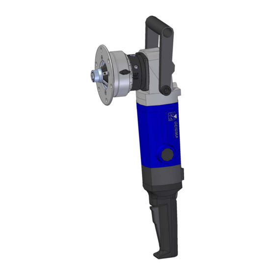
1 On/Off switch 7 Grip 2 Switch lock 8 Milling head with DL guide bearing 3 Speed adjustment 9 Height clamping screw 4 Motor 10 Vernier scale on collar 5 Spindle lock 11 Main scale 6 Guide plate Intended use: To avoid injury and damage to health, please The GERIMA SMA 50‐E is a hand‐held, electrically powered milling machine intended: observe the following: • for machining workpieces made of steel, cast steel, fine‐grained steel, stainless The machine may only be used for work and ma‐ steel, aluminium, aluminium alloys, brass terials described in the section ‘Intended use’. and plastics; • for commercial use in industrial settings and in the skilled trades; •... -
Page 9: Technical Data
Technical data Technical data: SMA 50‐E22 SMA 50‐E12 230 V 110/120 V Line voltage 50/60 Hz 50/60 Hz Mains frequency 2.200 W 1.800 W Rated power consumption ... - Page 10 Noise emissions Vibrations Noise emission values in accordance with the DIN EN 60745‐1 standard Noise emission Value Uncertainty Emission sound pressure level in dB(A) (in idle mode, speed pA setting: 4 of 6) pGpeak Peak emission sound pressure level at workplace (during milling operations) in dB(A) Sound power level ...
-
Page 11: Power-On Time
Power‐on time To avoid damaging the machine, it is essential The power‐on time is always expressed as a per‐ to be monitor how long the machine has been centage of one hour. operating continuously (‘power‐on time’). Example: If the power‐on time is specified as 50 %, then you All electric brushed motors generate large can use the machine to mill bevels for a maximum amounts of heat in the rotor and stator. Al‐ of 30 minutes in an hour and must then leave the though the machine is fitted with a fan cooler machine to cool for 30 minutes. If the machine is that dissipates the heat produced, if the ma‐ subjected to heavy loads, the power‐on time chine is subjected to extreme loads (e.g. milling might be 20 %, which means it can be used for large bevels, very hard or tough materials) and/ 12 minutes in any hour and must be left to cool or is run continuously for a long period of time, for 48 minutes. Before completely switching off the cooling system may not be able to cope with the machine, we recommend running the machine the amount of heat generated. If the operator for one or two minutes in idle mode (unloaded) so continues to use the machine, the rotor that fan can continue to draw cool air through the (armature) may overheat to such an extent that machine. the winding insulation melts causing a short cir‐ cuit. Power‐on time Speed adjustment ... -
Page 12: Adjusting The Bevel Height
Adjusting the bevel height 4. Machine adjustments Material and Bevel height (a) Bevel width tensile strength α = 30° α = 45° α = 60° C mm mm mm mm Aluminium 1 – 13.0 1 – 10.6 1 – 7.5 1.2 – 15.0 Steel up to 1 – 13.0 1 – 10.6 1 – 7.5 ... - Page 13 Adjusting the bevel height Small guide bearing (DS) Large guide bearing (DL) If the small guide bearing has been fitted, please If you have fitted the large guide bearing (DL), use the fixed main scale S (‘Skala S’) to determine please use the fixed main scale L (‘Skala L’) to the bevel height. With the DS guide‐bearing fitted, determine the bevel height. the cutting inserts can be indexed only four times, With the DL guide‐bearing fitted, type M cutting however it permits the machining of larger bevel inserts can be indexed a total of eight times. widths or smaller bore holes. Fixed main scale L Fixed main scale S ...
-
Page 14: Indexable Cutting Inserts For Milling Bevels
Indexable cutting inserts for milling bevels Eight‐fold indexable cutting inserts: The eight‐fold indexable cutting inserts are the Our universal B02 coating is a useful general‐ actual tools that perform the bevelling and de‐ purpose coating that can cope with all the above burring operations. They can be used to machine materials. plastic, steel, stainless steels and non‐ferrous metals such as copper aluminium and brass. They We also offer inserts with special coatings for ma‐ are suitable for cutting bevels at a variety of an‐ chining other more specialized materials. Please gles. contact us for details. Indexable cutting Type of coating Material strength Type B 00 Plastic B 00 Aluminium, copper or brass B 02 Steel up to 400 N/mm² B 02 ... - Page 15 Indexable cutting inserts for milling bevels Adjusting the eight‐fold indexable cutting inserts: CAUTION! It is extremely important to ensure that the lower corner of the cutting insert is always covered by the guide bearing DL or DS. The cutting inserts for milling edges must be fas‐...
- Page 16 Indexable cutting inserts for milling bevels Positioning of inserts on the milling head: 3 The type M indexable inserts have four cutting edges each 11 mm long. Our new technique of ‘rotating, flipping and shifting’ the inserts makes it possible to index each insert eight times if ma‐ chining bevels with widths of up to about 5 mm. If machining bevel widths greater than 5 mm, the cutting inserts can be indexed four times in Small guide bearing total. DS 1 The small guide bearing DS is used for milling con‐ tours and drilled holes with diameters ≥ 45 mm and for bevel widths in the range 1–10.0 mm. Large guide bearing 4 DL Large guide bearing DL fitted to milling head and cutting inserts fastened via locating hole 1. This configuration can be used to mill bevels with widths of up to 5.0 mm. Large guide bearing DL 2 Another option is to stagger the arrangement of the cutting inserts. By fixing the inserts alternately ...
-
Page 17: Indexable Cutting Inserts For Radius Milling
Indexable cutting inserts for radius milling Eight‐fold indexable radius‐milling inserts: The new indexable inserts used for radius milling operations can also be indexed a total of eight times before requiring replacement. They can be used for machining plastic, steel, stainless steel, as well as non‐ferrous metals such as aluminium, copper and brass. Material strength Type Radius 2 3 4 5 6 8 RM Type of coating Plastic B 00 B 00 B 00 B 00 B 00 B 00 Aluminium and aluminium alloys up to ... - Page 18 Indexable cutting inserts for radius milling Radius: 2.0 mm and 3.0 mm The indexable radius‐milling inserts RM 2 and RM 3 are designed with eight cutting edges. Our new technique of ‘rotating, flipping and shifting’ the inserts makes it possible to index these cut‐ Radius 2 mm/RM 2 Radius 3 mm/RM 3 ting inserts a total of eight times. Always use the original locking screws to fasten the radius‐milling inserts to the mounting seat on the milling head (max. tightening torque: 4.0– 5.0 Nm) Large guide bearing DL After shifting the radius‐milling inserts from locat‐ ing hole 1 to locating hole 2, the inserts can then be rotated and flipped a further four times. Large guide bearing DL ...
- Page 19 Indexable cutting inserts for milling bevels M Indexable cutting inserts for radius milling RM 3 Milling head MH‐45/R3‐A43.1 To mill 45° bevels, combine with a DL‐45/R3‐ A43‐1 guide bearing and fit type M indexable cutting inserts. To mill 3 mm radii, combine with the same guide bearing but fit RM 3 radius‐ milling inserts. ≤ 5mm = 8‐fold Standard 45° bevel, large guide bearing DL > 5mm = 4‐fold DL= large Combining the large DL‐45/R3‐A43.1 guide bear‐ ing with type M indexable cutting inserts, en‐ ables the inserts to be indexed a total of eight times if the bevel widths being machined are ≤ 5 mm, or indexed four times if the bevel widths are > 5 mm. or RM 3 = 8‐fold Radius: 3.0 mm The same DL guide‐bearing is used with the ...
- Page 20 Indexable cutting inserts for radius milling Adjusting the radii: Please note that only the position of the upper edge of the radius can be adjusted by rotating the guide plate. The lateral position of the radius on the workpiece end face is determined by the guide bearing fitted and cannot be altered. too low Guide plate set too low (Radius incomplete) ...
- Page 21 Indexable cutting inserts for radius milling Notes on radius milling: Choosing the right guide bearing to ensure the too large correct lateral position of the radius is just as important as setting the correct height of the guide plate. If the wrong guide bearing is used, the machined radius will not form a smooth transition with the Guide bearing too large (radius incomplete) end face of the workpiece. If the guide bearing used is too large, the ap‐ pearance of the resulting radius is similar (but too small rotated by 90°) to that created when the guide plate is set too low. If the guide bearing used is too small, the ap‐ pearance of the resulting radius is similar (but rotated by 90°) to that created when the guide Guide bearing too small (radius cuts into material) plate is set too high. The same phenomenon arises if the end and up‐...
-
Page 22: Working With The Machine
Machine operation 5. Machine operation Working with the bevelling machine: 1 Damage to equipment from incorrect supply voltage! • Check the mains (line) voltage. The mains voltage must agree with the details on the machine’s rating plate. Improper use can cause serious injury! • Make sure you always have a firm footing when working with the machine. 2 • Never touch the milling head when the machine is running. 1 Push the switch lock to the front of the ma‐ Risk of damage to equipment and property! chine and then depress the on/off switch 2 • Working with worn or damaged indexable until it clicks into place. cutting inserts or milling heads will cause the machine to fail. Motor starts • Avoid collisions when working with the Bring the machine slowly into contact with the machine. ... - Page 23 Machine operation Two‐handed operation: Whatever the position of the machine, always use two hands to control the machine. Ensure that the workpiece is securely clamped! • for safety reasons • to improve the service life of the cutting inserts • to prevent damage to the milling machine. Important! Before you begin machining the workpiece, When working with the machine, make sure that make sure that it is securely clamped so that it the machine is always held with two hands and in cannot slip. This should be done to ensure safe such a way that both hands are kept away from ...
-
Page 24: Maintenance Plan
Hot cutting inserts and milling head! Improperly repaired machines are a hazard! • Burn hazard! • Increased risk of injury! • Wear protective gloves when changing the • Machine does not function correctly. milling head. Repairs must only be carried out by a GERIMA‐ trained technician. 2 1 2 3 4 ... -
Page 25: Servicing
45 g grease Unscrew the brush holder caps. Caution! The guarantee will be void if re‐greasing is car‐ ried out by anyone other than a certified GERIMA service technician. Replenish with about 45 g of the high‐ performance lubricating grease Use a screwdriver to lever out the old brushes and 0101.204.04‐00018. then insert the new brushes. Reclose the opening by screwing the brush holder caps back into place. Service procedure 2 Service procedure 4 To ensure that the machine can be cooled prop‐ erly, the ventilation slots must be kept clean. To avoid damaging the motor windings, it is impor‐ tant that no foreign matter (e.g. chippings) enter the motor compartment. Clean the motor com‐... - Page 26 Replacing the milling head 7. 1 Replacing the milling head and guide bearing Lock spindle! 2 4 ...
- Page 27 Changing the guide bearing Changing the guide bearing Lock spindle! 1 2 1 Hex key (5 mm) 2 Guide bearing 3 Milling head 3 ...
-
Page 28: Radius Milling Cutter
Accessories: RM 2 Milling head MH‐45/R2‐A43.1 8. GERIMA spare parts Can be combined with a DL‐45/R2‐A43‐1 guide bearing and fitted with type M indexable cutting inserts for milling 45° bevels, or fitted with RM 2 radius‐milling inserts for milling 2 mm radii. 45° bevel, large guide bearing DL Combining the large DL‐45/R3‐A43.1 guide bear‐ ≤ 5 mm = 8‐fold ing with type M indexable cutting inserts, en‐ > 5 mm = 4‐fold ables the inserts to be indexed a total of eight Standard times if the bevel widths being machined are ≤ 5 mm, or indexed four times if the bevel DL= large widths are > 5 mm. Or RM 2 = 8‐fold Radius: 2.0 mm The same DL guide bearing is used with the eight‐fold indexable RM 2 radius‐milling inserts. ... - Page 29 Accessories: RK 4 Milling head MH‐45‐R4‐A44.1 fitted with a DL‐R4‐A44.1 guide bearing and RK 4 radius‐milling inserts for cutting 4 mm radii. Standard Radius: 4.0 mm DL= large RK 4 = 8‐fold DL‐R4‐44.1 guide bearing used with the eight‐ fold indexable RK 4 radius‐milling inserts. ...
- Page 30 Accessories: RL 6 Milling head MH‐R6‐A45.1 fitted with a DL‐R6‐A45.1 guide bearing and RL 6 radius‐milling inserts for cutting 6 mm radii. Standard DL= large Radius: 6.0 mm RL 6 = 8‐fold DL‐R6‐A45.1 guide bearing used with the eight‐ fold indexable RL 6 radius‐milling inserts ...
- Page 31 Accessories: RL 8 Milling head MH‐R8‐A45.1 fitted with a DL‐R8‐A45.1 guide bearing and RL 8 radius‐milling inserts for cutting 8 mm radii. Standard DL= large Radius: 8.0 mm RL 8 = 4‐fold DL‐R8‐A45.1 guide bearing used with the four‐ fold indexable RL 8 radius‐milling inserts. ...
-
Page 32: Adapter
Accessories: Adapter Adapter SK21.9 / M14 An adapter is required if special milling heads or 1 milling heads with a M14x1 threaded mount are to be used with the machine. The hexagonal adapter post is pushed into the socket that forms part of the drive shaft and then attached to the shaft by two hex socket cap screws. 3 2 By using the adapter, the former standard mill‐ ing heads with a M14x1 threaded mount are compatible with the new push‐on connection system. 3 In order to adjust the height correctly and to be able to use the scale when the adapter is fitted, the 20‐mm spacer ring m ust also be fitted. 6 4 ... - Page 33 Accessories: Adapter Attaching the adapter: 1. Loosen the four countersunk head screws on the guide‐plate and remove it from the adjuster ring. Place the 20‐mm spacer ring on the adjuster ring and secure it by tighten‐ Always disconnect from the power supply before ing the four screws. Now fasten the guide‐ working on the machine! plate unit onto the spacer ring. 2. Loosen the screws at the side of the guide plate unit and lift it off from the gear hous‐ ing. CAUTION 3. Place the adapter into the hexagonal socket that forms part of the drive shaft and fasten Do not lock by means of the two hex socket cap screws. spindle! To ensure a safe and secure fitting, use a medium‐strength thread locking sealant when tightening the screws. 1 4 4. Once the adapter has been fitted, place the milling head with the M14x1 threaded ...
-
Page 34: Guide Stop
Guide stop Guide stop The guide stop is used when milling bevels at an angel in the range 0°–80°on straight workpiece edges 8 7 1 2 3 6 Guide stop is simply and easily mounted on the 4 5 guide plate. 1 Retaining bracket ... -
Page 35: Grinding Systems
Accessories: Grinding heads 5. Grinding head B – single 1. Grinding adapter B (GAB 2.0) Grinding adapter B (GAB‐2.0) with grinding quill 40 mm comprising: with 1 x sleeve mounting drum BB 45/40 grinding adapter GAB‐2.0 ... - Page 36 Accessories: Diamond grinding heads 1. Grinding adapter GAD‐1.0 3. Diamond grinding head comprising: Possible configurations comprising: grinding adapter GAD‐1 grinding adapter D (GAD) diamond crown DC 0/28 locking bolt S1 ...
-
Page 37: Overview Of Indexable Cutting Inserts
Consumables 9. Consumables Overview and order numbers Material strength Indexable cutting inserts Aluminium Steel Steel Stainless Copper up to 600 up to 900 steel Type M indexable cutting insert Brass N/mm² N/mm² Order number Name of part Type Coating M‐B00‐A1.1 ... - Page 38 Consumables Overview and order numbers Material strength Indexable cutting inserts Alumin‐ Steel Steel Stainless Radius‐plate RM 2 ium up to 600 up to 900 steel Copper N/mm² N/mm² Order number Name of part Coating Brass RM2‐B00‐A1.1 B 00 x ...
-
Page 39: Gear Unit
Mechanical parts 28.01.2010 0101.153.09‐00012 Gear unit SMA 50‐E02 Exploded drawing GERIMA GERIMA Number number Order no. Name of part required 0101.143.09‐00035 Countersunk‐head screw M5x8 ... - Page 40 Spare parts list page 2 to 4 Mechanical parts 28.01.2010 Exploded drawing GERIMA GERIMA Number number Order no. Name of part required 0101.143.09‐00021 Cap head screw M5x12 ...
- Page 41 Exploded drawing of the gear unit V.02 .22.03.10.ENG...
-
Page 42: Drive Motor
28.01.2010 0101.293.08‐00002 Drive unit SMA 50‐E1 Exploded drawing GERIMA GERIMA Number number Order no. Name of part required 0101.203.08‐00073 Cap head screws M14x30 ... - Page 43 Elctromechanical parts 28.01.2010 Exploded drawing GERIMA GERIMA Number number Order no. Name of part required 0101.323.07‐00004 Brush holder ‐ 110 V‐ ...
- Page 44 Exploded drawing of the drive motor V.02 .22.03.10.ENG...
-
Page 45: 11. Guarantee
Guarantee 11. Guarantee GERIMA shall guarantee a new machine for a period of twelve months beginning on the damage arising from overloading the machine date the machine was purchased from the or from the incorrect use of the grinding tool; GERIMA production facility in 66606 the use of non‐genuine, unauthorized or de‐ St. Wendel, Germany. fective parts; damage caused by the machine to the workpiece; use of excessive force; con‐ Any further guarantees shall require the sequential damage arising from improper or prior written agreement of both the ma‐ inadequate maintenance by the customer or a chine owner and the manufacturer. third‐party; damage caused by unauthorized The guarantee provides that the machine is third‐parties or by the presence of foreign free from defects in materials and/or work‐ matter; damage arising from a failure to com‐ manship. Any performance data contained ply with the manufacturer’s operating instruc‐ in information or promotional materials or tions, e.g. connecting the machine to the included in quotations are understood to be wrong power supply. for guidance only and are not guaranteed, as Services provided under the guarantee are these values depend very strongly on the understood to be ‘ex works’ (66606 St. material worked and the particular machin‐ Wendel, Germany). ing operation used. Any additional costs, such as travel costs for Any guarantee claim submitted must state ... -
Page 46: Ec Declaration Of Conformity
This declaration will cease to be valid if any modifi‐ cations are made to the machine without our ex‐ press approval. The equipment complies with the essential re‐ quirements of the following EC directives: 2006/42/EC. ________________________________________________ Dipl. Ing. Stephan Rieth Managing Director ALME‐GERIMA GmbH Weimarer Str. 12 66606 St. Wendel Germany V.02 .22.03.10.ENG...
Need help?
Do you have a question about the SMA 50?E1 and is the answer not in the manual?
Questions and answers