Table of Contents
Advertisement
Quick Links
Advertisement
Table of Contents

Related Manuals for Gerima SMA 20?P 62


Summary of Contents for Gerima SMA 20?P 62
- Page 1 Operating Manual GERIMA SMA 20‐P 62 SMA 20‐P 62 V62.1.2 . 27.09.10.ENG ...
- Page 2 Your machine was subjected to thorough inspec‐ of specialist retailers and application technicians tion and testing before being packed and would be pleased to offer their assistance. shipped. 2. Servicing and repair issues Should you need to contact us for assistance, please always have the machine identification If you need to make a guarantee claim, if the ma‐ number available. chine needs to be repaired or if you need to order spare parts, please contact our specialist retailers for help. The machine identification number is printed 3. Sales on the machine’s rating plate. Our specialist retailers are also the people to con‐ tact if you wish to purchase additional GERIMA machines, accessories or consumable items. To help us provide quick and efficient assistance, Machine‐No. please always have your machine identification number to hand. We hope you enjoy working with your precision‐ made GERIMA machine. The GERIMA Team V62.1.2 . 27.09.10.ENG ...
-
Page 3: Table Of Contents
7. Replacing the milling head and Changing the milling head and the guide bearing DL/DS guide bearings 26 8. GERIMA spare parts Radius milling cutter 28 9. Consumables Overview of indexable cutting inserts 29 10. Spare and wearing parts ... -
Page 4: Adjusting The Bevel Height
Quick reference guide 1. Quick reference guide Working direction: Separate air connection Always mill against the direction of rotation of the milling head (‘up‐cut milling’) Changing the milling head: Move machine ONLY in the direction of the arrow! Adjusting bevel height (a): The bevel height (a) – see page 12 – is set by ad‐ justing the height of the machine’s guide plate. The height setting can be read from the fixed main scale and the vernier collar. On/Off 1. Release clamping screw ... -
Page 5: Changing The Guide Bearing
Quick reference guide Changing the indexable inserts: Separate air connection V62.1.2 . 27.09.10.ENG ... -
Page 6: General Safety Information
Safety information 2. Safety information General safety information: Only use the recommended lubricants. Check pneumatic tubing and air pressure. When the machine is running, the air pressure at the tool inlet should not exceed 7 bar (= 700 kPa = 100 psi), or a lower maximum operating air pressure if Before using the machine, the operating manual specified. and safety information must have been read and understood in their entirety. The instructions Avoid hazards associated with vibrating contained therein must be followed. pneumatic tubing. Check the condition of the These operating instructions are based on the tubing, tube connectors and tube clamps relevant parts of the European Machinery regularly. Directive (98/37/EC) and the CEN TC 255 regulations “Hand‐held, non‐electric power tools Make sure that the exhaust air vent is positioned – Safety”. so that dust or air drawn from the workpiece is not directed toward the operator or any other person. These instructions cover the operation and han‐ A safety screen should, if possible, be positioned dling of the machine, including tools, accessories between the operator and the and machine maintenance. ... -
Page 7: Specific Safety Instructions
Never lift or carry the machine by its chine is running. power cable. • Never use the machine above head height. • Make sure the cable is directed behind • The machine should only be used for con‐ and away from the machine. Do not lay ventional up‐cut milling. the cable over sharp edges. • Servicing and testing must only be carried out by appropriately qualified technicians. • Always use genuine GERIMA spare parts and accessories. Important The manufacturer reserves the right to make technical changes. V62.1.2 . 27.09.10.ENG ... -
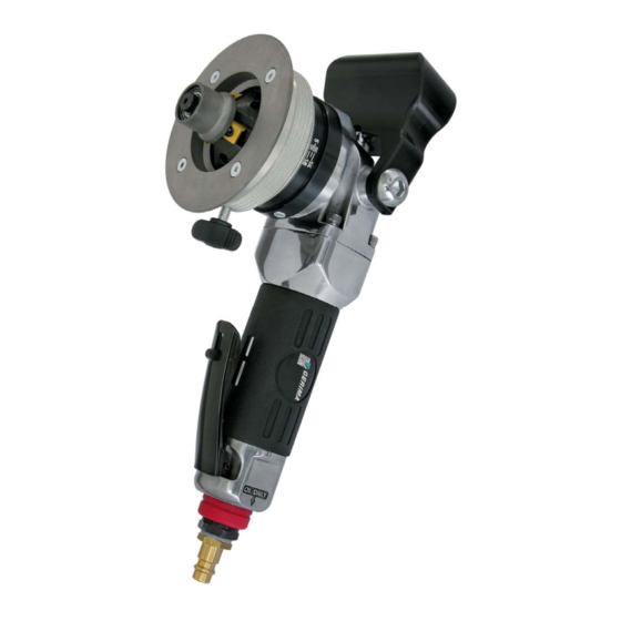
Page 8: Functional Components
Air‐Motor 2 9 Height clamping screw 3 Main scale 10 Paddle switch (starter lever) 4 Guide plate 5 Grip Intended use: The GERIMA SMA 20‐P is a hand‐held, pneumati‐ cally driven device intended: To avoid injury and damage to health, please • for machining workpieces made of steel, observe the following: cast steel, fine‐grained steel, stainless steel, aluminium, aluminium alloys, brass and plastics; The machine may only be used for work and • for commercial use in industrial settings materials described in the section ‘Intended and in the skilled trades; • for preparing K, V, X and Y‐shaped welding use’. ... -
Page 9: Technical Data
Technical data SMA 20 ‐ P 62 Technical data: 6‐7 bar Air pressure 20 l/s Required air flow rate 800 W Rated power consumption 8.000 1/min Motor speed when idling 2,5 kg Weight (approx.) ... - Page 10 Noise emissions Vibrations Noise emission values in accordance with the DIN EN 60745‐1 standard Noise emission Value Uncertainty Emission sound pressure level in dB(A) 83 3 (in idle mode, speed set‐ pA Peak emission sound pressure level at workplace 101 3 pGpeak (during milling operations) in dB(A) 94 3 Sound power level ...
-
Page 11: Power-On Time
Power‐on time The power‐on time is always expressed as a percentage of one hour. The compressed air that powers a pneumatic Example: drive also serves to cool the motor as well. Pneu‐ matic tools can therefore be operated for longer If the power‐on time is specified as 50 %, then you periods than electrically powered tools. can use the machine to mill bevels for a maximum However, if the machine is subjected to particu‐ of 30 minutes in an hour and must then leave the larly extreme loads (e.g. when machining wide machine to cool for 30 minutes. If the machine is bevels or very hard or tough materials) and/or if subjected to heavy loads, the power‐on time the machine is run for very long periods, the air might be 20 %, which means it can be used for cooling may still be insufficient to prevent over‐ 12 minutes in any hour and must be left to cool for heating of the milling drive unit. If the operator 48 minutes. continues to use the machine, the milling drive unit may overheat and be damaged as a result. Material strength Power‐on time ... -
Page 12: Adjusting The Bevel Height
Adjusting the bevel height 4. Machine adjustments Material and ten‐ Bevel height (a) Bevel width sile strength Material and ten‐ α = 30° α = 45° sile strength mm mm Aluminium 1-8,7 1-7,1 1,2-10... -
Page 13: Indexable Cutting Inserts For Milling Bevels
Indexable cutting inserts for milling bevels Eight‐fold indexable cutting inserts: The eight‐fold indexable cutting inserts are the Our universal B02 coating is a useful general‐ actual tools that perform the bevelling and de‐ purpose coating that can cope with all the above burring operations. They can be used to machine materials. plastic, steel, stainless steels and non‐ferrous metals such as copper aluminium and brass. We also offer inserts with special coatings for ma‐ They are suitable for cutting bevels with angles chining other more specialized materials. Please of 30° or 45°. contact us for details Indexable cutting insert Type of coating Material strength Type Plastic B 00 M Aluminium, copper ... -
Page 14: Indexable Cutting Inserts For Radius Milling
Indexable cutting inserts for milling bevels Adjusting the eight‐fold indexable cutting inserts: CAUTION! It is extremely important to ensure that the lower corner of the cutting insert is always covered by the guide bearing DL or DS. The cutting inserts for milling edges must be fas‐ tened to the mounting seat on the milling head by Locating hole 1 means of the original locking screws (max. tighten‐ ing torque: 4.0–5.0 Nm). As each insert has four cutting edges, it can each ... - Page 15 Indexable cutting inserts for milling bevels Positioning of inserts on the milling head: 3 The type M indexable inserts have four cutting edges each 11 mm long. Our new technique of ‘rotating, flipping and shifting’ the inserts makes it possible to index each insert eight times if ma‐ chining bevels with widths of up to about 5 mm. If machining bevel widths greater than 5 mm, the cutting inserts can be indexed four times in small guide bearing total. DS 1 The small guide bearing DS is used for milling con‐ tours and drilled holes with diameters ≥ 45 mm Large guide bearing and for bevel widths in the range 1–10.0 mm ...
- Page 16 Indexable cutting inserts for radius milling Eight‐fold indexable radius‐milling inserts: The new indexable inserts used for radius milling operations can also be indexed a total of eight times before requiring replacement. They can be used for machining plastic, steel, stainless steel, as well as non‐ferrous metals such as aluminium, copper and brass. Radius Type Material strength 2 3 RM Type of coating Aluminium and aluminium alloys up to B 00 B 00 250 N/mm² Steel up to 400 N/mm² B 02 B 02 Steel up to 600 N/mm² B 02 B 02 Steel up to 900 N/mm² B 05 B 05 ...
- Page 17 Indexable cutting inserts for radius milling Radius: 2.0 mm and 3.0 mm The indexable radius‐milling inserts RM 2 and RM 3 are designed with eight cutting edges. Our new technique of ‘rotating, flipping and shifting’ the inserts makes it possible to index these cut‐ Radius 2 mm/RM2 Radius 3 mm/RM 3 ting inserts a total of eight times. Always use the original locking screws to fasten the radius‐milling inserts to the mounting seat on the milling head (max. tightening torque: 4.0– 5.0 Nm) Large guide bearing DL ...
- Page 18 Indexable cutting inserts for milling bevels M Indexable cutting inserts for radius milling RM 3 Milling head MH‐45/R3‐AB33.1 To mill 45° bevels, combine with a DL‐45/R3‐B33‐1 guide bearing and fit type M indexable cutting in‐ serts. To mill 3 mm radii, combine with the same ≤ 5 mm = 8‐fold guide bearing but fit RM 3 radius‐milling inserts. > 5 mm = 4‐fold 45° bevel, large guide bearing DL Combining the large DL‐45/R3‐B33.1 guide bearing Standard with type M indexable cutting inserts, enables the DL= large inserts to be indexed a total of eight times if the bevel widths being machined are ≤ 5 mm, or in‐ dexed four times if the bevel widths are > 5 mm. or RM3 = 8‐fold Radius: 3.0 mm The same DL guide‐bearing is used with the eight‐ fold indexable RM 3 radius‐milling inserts. Alternativ ...
- Page 19 Indexable cutting inserts for radius milling Adjusting the radii: Please note that only the position of the upper edge of the radius can be adjusted by rotating the guide plate. The lateral position of the radius on the workpiece end face is determined by the guide bearing fitted and cannot be altered too low Guide plate set too low (Radius incomplete) too high Guide plate set too high (Radius cuts into material) ...
- Page 20 Indexable cutting inserts for radius milling Notes on radius milling: Choosing the right guide bearing to ensure the correct lateral position of the radius is just as important as setting the correct height of the too large guide plate. If the wrong guide bearing is used, the machined radius will not form a smooth transition with the end face of the workpiece. If the guide bearing used is too large, the ap‐ pearance of the resulting radius is similar (but Guide bearing too large (radius incomplete) rotated by 90°) to that created when the guide plate is set too low. If the guide bearing used is too small, the ap‐ pearance of the resulting radius is similar (but rotated by 90°) to that created when the guide too small plate is set too high. The same phenomenon arises if the end and up‐ per faces of the workpiece are not aligned at right angles to one another. ...
-
Page 21: Working With The Machine
Machine operation 5. Machine operation Working with the bevelling machine: Excessive air pressure can damage equipment! • The input air pressure must agree with the details on the machine’s rating plate. Improper use can cause serious injury! • Make sure you always have a firm footing when working with the machine. • Never touch the milling head when the machine is running. 10 Risk of damage to equipment and property! • Working with worn or damaged indexable cutting inserts or milling heads will cause Depress the switch 10 the machine to fail. • Avoid collisions when working with the Motor starts machine. Bring the machine slowly into contact with the workpiece only after the selected tool speed has been reached. ... - Page 22 Machine operation Two‐handed operation: Whatever the position of the machine, always use two hands to control the machine. Ensure that the workpiece is securely clamped! • for safety reasons • to improve the service life of the cutting inserts • to prevent damage to the milling machine. Important! When working with the machine, make sure that Before you begin machining the workpiece, the machine is always held with two hands and in make sure that it is securely clamped so that it such a way that both hands are kept away from ...
-
Page 23: Maintenance Plan
Make sure that the machine is completely depressurized before attempting to change the justing the indexable cutting inserts. cutting tool or carry out maintenance work. Improperly repaired machines are a hazard! • Increased risk of injury! Hot cutting inserts and milling head! • Machine does not function correctly. • Burn hazard! • Wear protective gloves when changing the Repairs must only be carried out by a GERIMA‐ milling head. trained technician. 1 2 Wartungs‐Plan Type of maintenance Servicing to be ... -
Page 24: Servicing
Servicing Service procedure Service procedure 2 1a Re‐greasing Caution! The guarantee will be void if the air motor rotor To re‐grease the gear head, use only GERIMA vanes are replaced by anyone other than a certi‐ fied GERIMA service technician. special lubricating grease (0109.007.10‐00002) and inject the grease into the gearing head using Service procedure 3 a high‐pressure push‐type grease gun with a conical nozzle. Place the nozzle of the grease gun into the gear box lubrication opening and carefully discharge one or two units of grease into the gear housing. • Unscrew and remove the guide plate, • rotate and remove the guide‐plate mount‐ ing flange, • clean the mounting thread, lubricate the ... - Page 25 Servicing Use only genuine GERIMA spare parts and For simple fast delivery of these items, please consumables when servicing your machine. contact us and quote the following order num‐ bers: Bestell‐Nr. High‐pressure push‐type 0109.007.10‐00001 grease gun Special lubricating grease 0109.007.10‐00002 100 ml. ...
- Page 26 Replacing the milling head . Replacing the milling head and guide bearing Separate air connection 1 4 ...
- Page 27 Changing the guide bearing Changing the guide bearing 1 2 1 Hex key (3 mm) 2 Guide bearing 3 3 Milling head 4 ...
-
Page 28: Radius Milling Cutter
Accessories: RM 2 8. GERIMA spare parts Milling head MH‐45/R2‐B33.1 Can be combined with a DL‐45/R2‐B33‐1 guide bearing and fitted with type M indexable cutting inserts for milling 45° bevels, or fitted with RM 2 radius‐milling inserts for milling 2 mm radii. 45° bevel, large guide bearing DL Combining the large DL‐45/R3‐B33.1 guide bearing Standard ≤ 5 mm = 8‐fold with type M indexable cutting inserts, enables the inserts to be indexed a total of eight times if the > 5 mm = 4‐fold DL= large bevel widths being machined are ≤ 5 mm, or in‐ dexed four times if the bevel widths are > 5 mm. Or Radius: 2.0 mm The same DL guide bearing is used with the eight‐ RM 2 = 8‐fold fold indexable RM 2 radius‐milling inserts. Alternative ... -
Page 29: Overview Of Indexable Cutting Inserts
Consumables 9. Consumables Overview and order numbers Material strength Indexable cutting inserts Aluminium Steel Steel Copper up to up to Brass 600 N/ 900 N/ Type M indexable cutting insert Order number mm² mm² Name of part Type Coating M‐B00‐A1.1 M B 00 x 0101.404.09‐00001 ... -
Page 30: Gear Unit
Mechanical parts 11.02.2010 0101.243.09‐00005 Gear unit SMA 20‐P Exploded drawing GERIMA GERIMA Number number Order no. Name of part required 1 0101.243.08‐00007 Countersunk‐head screw M4x10 4 2 0101.243.08‐00001 Guide plate SMA 20‐P 1 1 3 0101.243.08‐00008 O‐Ring 52,07x2,62 1 ... - Page 31 Spare parts – Gear unit V62.1.2 . 27.09.10.ENG ...
- Page 32 pneumatic 23.03.2010 0101.243.08‐00018 pneumatic drive unit SMA 20‐P Exploded drawing GERIMA GERIMA Number number Order no. Name of part required 100 0109.113.09‐00018 spring washer 4 101 0109.113.09‐00017 screw 4 102 0109.113.09‐00010 set screw 1 103 ...
- Page 33 SMA 20‐P62_1.1 Spare parts list Page 3 of 3 pneumatic 23.03.2010 exploded drawing‐ GERIMA GERIMA Required no. oder‐ No. Description Quantity 121 0109.113.09‐00029 rotor blade 1 122 0109.113.09‐00030 rotor 1 123 0109.113.09‐00031 rear plate 1 124 ...
-
Page 34: Pneumatic Motor
Pneumatikmotor V62.1.2 . 27.09.10.ENG ... -
Page 35: 11. Guarantee
Guarantee 11. Guarantee GERIMA shall guarantee a new machine for a period of twelve months beginning on the damage arising from overloading the machine date the machine was purchased from the or from the incorrect use of the grinding tool; GERIMA production facility in 66606 the use of non‐genuine, unauthorized or de‐ St. Wendel, Germany. fective parts; damage caused by the machine to the workpiece; use of excessive force; con‐ Any further guarantees shall require the sequential damage arising from improper or prior written agreement of both the ma‐ inadequate maintenance by the customer or a chine owner and the manufacturer. third‐party; damage caused by unauthorized The guarantee provides that the machine is third‐parties or by the presence of foreign free from defects in materials and/or work‐ matter; damage arising from a failure to com‐ manship. Any performance data contained ply with the manufacturer’s operating instruc‐ in information or promotional materials or tions, e.g. connecting the machine to the included in quotations are understood to be wrong power supply. for guidance only and are not guaranteed, as Services provided under the guarantee are these values depend very strongly on the understood to be ‘ex works’ (66606 St. material worked and the particular machin‐ Wendel, Germany). ing operation used. Any additional costs, such as travel costs for Any guarantee claim submitted must state ... -
Page 36: Ec Declaration Of Conformity
EC Declaration of Conformity 12. EC Declaration of Conformity We hereby declare SMA 20‐P62 that the equipment conforms to the relevant fundamental safety and health requirements of the EC Machinery Directive 2006/42/EC, both in its basic design and construction as well as in the version marketed by us. The equipment complies with the essential requirements of the following EC directives: 2006/42/EC, DIN EN 111 48. Technical documents by: ALME GERIMA GmbH Department: D‐Tech Weimarer Str. 12 66606 St. Wendel St. Wendel, den 27.09.2010 Dipl.‐Ing. Stephan Rieth Managing Director ALME‐GERIMA GmbH Weimarer Str. 12 66606 St. Wendel Germany ...
Need help?
Do you have a question about the SMA 20?P 62 and is the answer not in the manual?
Questions and answers