
Related Manuals for Gerima SMA 30-p 62


Summary of Contents for Gerima SMA 30-p 62
- Page 1 Opera ng Manual GERIMA SMA 30‐P 62 SMA 30‐P 62 Star ng with the machine iden fica on number 11‐157‐00013 V01_157_ 01.01.2014.ENG ...
- Page 2 2. Servicing and repair issues shipped. If you need to make a guarantee claim, if the ma‐ Should you need to contact us for assistance, chine needs to be repaired or if you need to order please always have the machine iden fica on spare parts, please contact our specialist retailers number available. for help. 3. Sales The machine iden fica on number is printed Our specialist retailers are also the people to con‐ on the machine’s ra ng plate. tact if you wish to purchase addi onal GERIMA machines, accessories or consumable items. To help us provide quick and efficient assistance, please always have your machine iden fica on number to hand. Machine‐No. We hope you enjoy working with your precision‐ made GERIMA machine. The GERIMA Team ...
-
Page 3: Table Of Contents
Servicing 7. Replacing the milling head and Changing the milling head and the guide bearing DL/DS guide bearings 25 8. GERIMA spare parts Radius milling cu er 27 9. Consumables Overview of indexable cu ng inserts 29 10. Spare and wearing parts Gear unit ... -
Page 4: Adjus Ng The Bevel Height
Quick reference guide 1. Quick reference guide Changing the milling head: Working direc on: Seperate air connec on 1 Adjustment Move machine ONLY in the direc on of the 2 5 Arrow! Adjus ng bevel height: The bevel height is set by adjus ng the height of the machine’s guide plate. The height se ng can be read from the fixed main scale and the vernier collar. ... -
Page 5: Changing The Guide Bearing
Quick reference guide Changing the indexable inserts: Seperate air connec on 1 4 Adjustment 4-5 Nm 5 2 6 3 V01_157_ 01.01.2014.ENG ... -
Page 6: General Safety Informa On
Safety informa on 2. Safety informa on Check pneuma c tubing and air pressure. General safety informa on: When the machine is running, the air pres‐ sure at the tool inlet should not exceed 7 bar (= 700 kPa = 100 psi), or a lower maxi‐ mum opera ng air pressure if specified. Avoid hazards associated with vibra ng Before using the machine, the opera ng manual pneuma c tubing. Check the condi on of and safety informa on must have been read and the tubing, tube connectors and tube understood in their en rety. The instruc ons clamps regularly. contained therein must be followed. Make sure that the exhaust air vent is posi‐ These opera ng instruc ons are based on the oned so that dust or air drawn from the ... -
Page 7: Specific Safety Instruc Ons
Never li or carry the machine by its pow‐ er cable. Make sure the cable is directed behind and away from the machine. Do not lay the cable over sharp edges. Servicing and tes ng must only be carried out by appropriately qualified technicians. Important Always use genuine GERIMA spare parts and accessories. The manufacturer reserves the right to make technical changes. V01_157_ 01.01.2014.ENG ... -
Page 8: Func Onal Components
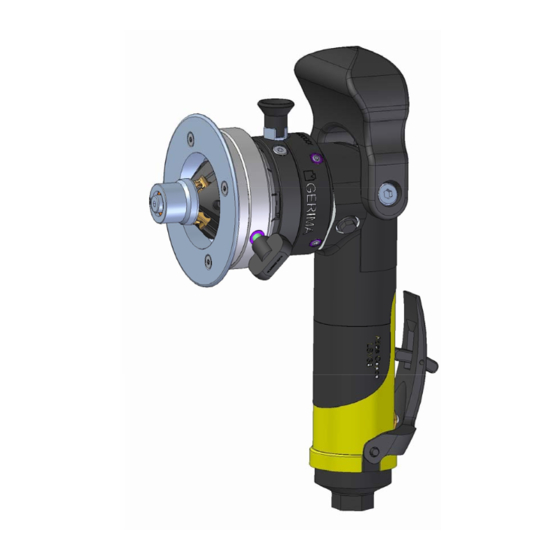
Milling head 3 Main scale 8 (DL) guide bearing 4 Guide plate 9 Height clamping screw 5 Grip 10 Paddle switch (starter lever) Intended use: The GERIMA SMA 30‐P is a hand‐held, pneuma ‐ To avoid injury and damage to health, please cally driven device intended: observe the following: for machining workpieces made of steel, fine‐grained steel, aluminium, aluminium The machine may only be used for work and alloys, brass and plas cs; materials described in the sec on ‘Intended for commercial use in industrial se ngs use’. and in the skilled trades; ... -
Page 9: Technical Data
Technical data Technical data: SMA 30 ‐ P 62 6 bar Air pressure 28 l/s Required air flow rate 1300 W Rated power consump on 8.500 1/min Motor speed when idling 2,5 kg Weight (approx.) Bevel width (material‐dependent) ... - Page 10 Noise emissions Vibra ons Noise emission values in accordance with the DIN EN 60745‐1 standard Noise emission Value Uncertainty Emission sound pressure level (in idle mode, speed in dB(A) 83 3 pA 101 3 Peak emission sound pressure level at workplace pGpeak (during milling opera ons) in dB(A) 94 3 Sound power level Vibra ons: Determined as per EN 60745: ...
-
Page 11: Power-On Me
On – Time The power‐on me is always expressed as a percentage of one hour. The compressed air that powers a pneuma c Example: drive also serves to cool the motor as well. Pneu‐ If the power‐on me is specified as 50 %, then you ma c tools can therefore be operated for longer can use the machine to mill bevels for a maximum periods than electrically powered tools. of 30 minutes in an hour and must then leave the However, if the machine is subjected to par cu‐ machine to cool for 30 minutes. If the machine is larly extreme loads (e.g. when machining wide subjected to heavy loads, the power‐on me bevels or very hard or tough materials) and/or if might be 20 %, which means it can be used for the machine is run for very long periods, the air 12 minutes in any hour and must be le to cool for cooling may s ll be insufficient to prevent over‐ 48 minutes. hea ng of the milling drive unit. If the operator con nues to use the machine, the milling drive ... -
Page 12: Adjus Ng The Bevel Height
Adjus ng the bevel height 4. Machine adjustments Material and tensile Bevel height (a) Bevel width strength α = 30° α = 45° mm mm Aluminium 1-8,7 1-7,1 1,2-10 Steel up to 1-3,5 1-2,8 1,2-4,0 400 N/mm² a length of adjacent leg = bevel height (a) b length of opposite leg = bevel height (b) Steel up to 1-2,6 1-2,1 1,2-3,0 600 N/mm² C bevel width Steel up to 1-1,7 1-1,4 1,2-2,0 α bevel angle ... -
Page 13: Indexable Cu Ng Inserts For Milling Bevels
Indexable cu ng inserts for milling bevels Eight‐fold indexable cu ng inserts: The eight‐fold indexable cu ng inserts are the Our universal B02 coa ng is a useful general‐ actual tools that perform the bevelling and de‐ purpose coa ng that can cope with all the above burring opera ons. They can be used to machine materials. plas c, steel, stainless steels and non‐ferrous metals such as copper aluminium and brass. We also offer inserts with special coa ngs for ma‐ They are suitable for cu ng bevels with angles chining other more specialized materials. Please of 30° or 45°. contact us for details ... - Page 14 Indexable cu ng inserts for milling bevels Adjus ng the eight‐fold indexable cu ng inserts: CAUTION! It is extremely important to ensure that the lower cor‐ ner of the cu ng insert is always covered by the guide bearing DL or DS. Loca ng hole 1 The cu ng inserts for milling edges must be fas‐ ...
- Page 15 Indexable cu ng inserts for milling bevels Posi oning of inserts on the milling head: 3 The type M indexable inserts have four cu ng edges each 11 mm long. Our new technique of ‘rota ng, flipping and shi ing’ the inserts makes it possible to index each insert eight mes if ma‐ chining bevels with widths of up to about 5 mm. If machining bevel widths greater than 5 mm, the cu ng inserts can be indexed four mes in Small guide bearing total. DS 1 ...
-
Page 16: Indexable Cu Ng Inserts For Radius Milling
Indexable cu ng inserts for radius milling Eight‐fold indexable radius‐milling inserts: The new indexable inserts used for radius milling opera ons can also be indexed a total of eight mes before requiring replacement. They can be used for machining plas c, steel, stainless steel, as well as non‐ferrous metals such as aluminium, copper and brass. Material strength Typ Type of coa ng RM 2 3 Plas c B 00 B 00 Aluminium and aluminium alloys up B 00 B 00 To 250 N/mm² Steel up to 400 N/mm² B 02 B 02 Steel up to 600 N/mm² B 02 B 02 ... - Page 17 Indexable cu ng inserts for radius milling Radius: 2.0 mm and 3.0 mm The indexable radius‐milling inserts RM 2 and RM 3 are designed with eight cu ng edges. Our new technique of ‘rota ng, flipping and shi ing’ the inserts makes it possible to index these cu ng inserts a total of eight mes. Large guide bearing Always use the original locking screws to fasten DL the radius‐milling inserts to the moun ng seat on the milling head (max. ghtening torque: 4.0– 5.0 Nm) A er shi ing the radius‐milling inserts from lo‐ ca ng hole 1 to loca ng hole 2, the inserts can ...
- Page 18 Indexable cu ng inserts for milling bevels M Indexable cu ng inserts for radius milling RM 3 Milling head MH‐45/R3‐L‐B33.1 To mill 45° bevels, combine with a DL‐45/R3‐B33‐1 guide bearing and fit type M indexable cu ng in‐ serts. To mill 3 mm radii, combine with the same ≤ 5 mm = 8‐fold guide bearing but fit RM 3 radius‐milling inserts. > 5 mm = 4‐fold Standard DL= large 45° bevel, large guide bearing DL Combining the large DL‐45/R3‐B33.1 guide bearing with type M indexable cu ng inserts, enables the inserts to be indexed a total of eight mes if the RM3 = 8‐fold bevel widths being machined are ≤ 5 mm, or in‐ dexed four mes if the bevel widths are > 5 mm. ...
- Page 19 Indexable cu ng inserts for radius milling Adjus ng the radii: Please note that only the posi on of the upper edge of the radius can be adjusted by rota ng the guide plate. The lateral posi on of the radius on the workpiece end face is determined by the guide bearing fi ed and cannot be altered Too low Guide plate set too low (Radius incomplete) Too high Guide plate set too high (Radius cuts into material) ...
- Page 20 Indexable cu ng inserts for radius milling Notes on radius milling: Choosing the right guide bearing to ensure the correct lateral posi on of the radius is just as important as se ng the correct height of the too large guide plate. If the wrong guide bearing is used, the machined radius will not form a smooth transi on with the end face of the workpiece. Guide bearing too large (radius incomplete) If the guide bearing used is too large, the ap‐ pearance of the resul ng radius is similar (but rotated by 90°) to that created when the guide plate is set too low. too small If the guide bearing used is too small, the ap‐ pearance of the resul ng radius is similar (but ...
-
Page 21: Working With The Machine
Machine opera on 5. Machine opera on Working with the bevelling machine: Excessive air pressure can damage equipment! 10 The input air pressure must agree with the details on the machine’s ra ng plate. Improper use can cause serious injury! Make sure you always have a firm foo ng when working with the machine. Never touch the milling head when the machine is running. Depress the switch 10 Risk of damage to equipment and property! Motor starts Working with worn or damaged indexable cu ng inserts or milling heads will cause Bring the machine slowly into contact with the the machine to fail. workpiece only a er the selected tool speed has ... - Page 22 Machine opera on Two‐handed opera on: Whatever the posi on of the machine, always use two hands to control the machine. Ensure that the workpiece is securely clamped! for safety reasons to improve the service life of the cu ng inserts to prevent damage to the milling ma‐ chine. Important! When working with the machine, make sure that Before you begin machining the workpiece, the machine is always held with two hands and in ...
-
Page 23: Maintenance Plan
Hot cu ng inserts and milling head! Improperly repaired machines are a hazard! Burn hazard! Increased risk of injury! Wear protec ve gloves when changing the Machine does not func on correctly. milling head. Repairs must only be carried out by a GERIMA‐ trained technician. 1 2 Maintenance plan Type of maintenance Servicing to be Maintenance proce‐... -
Page 24: Servicing
Service procedure 3 Service procedure 1 Unscrew and remove the guide plate, Full grease replacement rotate and remove the guide‐plate moun ng flange, Full replacement of the lubrica ng grease re‐ clean the moun ng thread, lubricate the quires removing the gearing housing from the thread with teflon spray and then re‐ machine and should therefore only be carried assemble in reverse order. out by a cer fied GERIMA service technician. Service procedure 2 motor lamina ons replacement ... - Page 25 Replacing the milling head . Replacing the milling head and guide bearing DO NOT PRESS! Separate air connec on Remove the 3 locking screws and with‐ 2 draw the guide plate unit. A erwards you can 1 arrest the axle drive sha vie the ming tool. Then you can detach the milling head ...
- Page 26 Changing the guide bearing Changing the guide bearing PRESS! 1 1 Hex key (3 mm) 2 2 Guide bearing ...
-
Page 27: Radius Milling Cu Er
Accessories: RM 2 Milling head MH–45/R2‐L‐B33.1 8. GERIMA spare parts Can be combined with a DL‐45/R2‐B33‐1 guide bearing and fi ed with type M indexable cu ng inserts for milling 45° bevels, or fi ed with RM 2 radius‐milling inserts for milling 2 mm radii. 45° bevel, large guide bearing DL Standard ≤ 5 mm = 8‐fold > 5 mm = 4‐fold Combining the large DL‐45/R3‐B33.1 guide bearing DL = large with type M indexable cu ng inserts, enables the inserts to be indexed a total of eight mes if the bevel widths being machined are ≤ 5 mm, or in‐ dexed four mes if the bevel widths are > 5 mm. Or ... - Page 28 Accessories: RM 4 Milling head MH–R4‐L‐B34.1 GERIMA spare parts ist mit einem Führungslager DL‐R4‐B34.1 zum Fräsen von Radius 4 mm mit Radius‐Wendeschneidpla e RK4 ausgerüstet. Standard RK 4 = 8‐fold DL= large Radius 4,0 mm Das DL wird genutzt für den 8‐fachen Einsatz der Radius ‐Wendeschneidpla en Typ RK 4. ...
- Page 29 Consumables 9. Consumables Overview and order numbers Material strength Indexable cu ng inserts Aluminium Steel Steel Copper up to up to Type M indexable cu ng insert Brass 600 N/ 900 N/ Order number mm² mm² Name of part Typ Coa ng x ...
-
Page 30: Gear Unit
Mechanical parts 11.02.2011 0109.173.10‐00038 Gear unit SMA 30‐P Exploded drawing GERIMA GERIMA Number number Order no. Name of part required 1 0109.173.10‐00048 Countersunk‐head screw M4x10 4 2 0109.173.10‐00049 Wing bolt 1 3 0109.173.10‐00050 Threaded insert M6x7,5 1 4 ... - Page 31 Spare parts – Gear unit V01_157_ 01.01.2014.ENG ...
-
Page 32: Pneuma C Motor
Pneuma c drive 11.02.2011 0109.173.10‐00039 Pneuma c drive unit SMA 30‐P Exploded drawing GERIMA GERIMA Number number Order no. Name of part required 100 0109.173.10‐00001 Cover cap 1 101 0109.173.10‐00002 Screw 4 102 0109.173.10‐00003 Spring washer 1 ... - Page 33 Spare parts list Pneuma c drive 11.02.2011 Exploded drawing GERIMA GERIMA Number number Order no. Name of part required 120 (121‐122) 0109.173.10‐00012 Oil stopper, complete 1 121 O‐ Ring 1 Service Kit 122 stopper 1 No selling part 123 ...
- Page 34 Spare parts ‐ pneuma c drive V01_157_ 01.01.2014.ENG ...
- Page 35 Spare parts list Pneuma c drive 11.02.2011 Exploded drawing GERIMA GERIMA Number number Order no. Name of part required 133 0109.173.10‐00015 Bevel wheel 1 134 Ball bearing 1 Service Kit 135 O‐ Ring 1 Service Kit 136 ...
- Page 36 Spare parts ‐ pneuma c drive V01_157_ 01.01.2014.ENG ...
- Page 37 Spare parts list Pneuma c drive 11.02.2011 Exploded drawing GERIMA GERIMA Number number Order no. Name of part required 147 (148‐153) 0109.173.10‐00023 Spare parts ‐ air intrance 1 148 0109.173.10‐00024 Body housing ‐ air intrance 1 149 O‐ Ring 1 Service Kit 150 ...
- Page 38 Spare parts ‐ pneuma c drive V01_157_ 01.01.2014.ENG ...
-
Page 39: Guarantee
Services provided under the guarantee are for guidance only and are not guaranteed, as understood to be ‘ex works’ (66606 St. Wen‐ these values depend very strongly on the del, Germany). material worked and the par cular machin‐ Any addi onal costs, such as travel costs for ing opera on used. technical personnel, shipping costs etc. are Any guarantee claim submi ed must state not covered by the guarantee and will be the machine iden fica on number and must charged. be accompanied by the relevant delivery A er receiving a defec ve machine, GERIMA note or invoice. shall compile a cost es mate of the repairs Repairs under guarantee may only be carried and shall provide no fica on of the extent to out by GERIMA or by one of its authorized which these repairs are covered by the guar‐ specialist retailer or representa ves. antee. Once accepted, the machine will be repaired Guarantee claims can be made only for gen‐ and then either dispatched with invoice or uine GERIMA parts and if the machine was ... -
Page 40: Ec Declara On Of Conformity
EC Declara on of Conformity 12. EC Declara on of Conformity We hereby declare SMA 30‐P62 that the equipment conforms to the relevant fundamental safety and health requirements of the EC Machinery Direc ve 2006/42/EC, both in its basic design and construc on as well as in the version marketed by us. The equipment complies with the essen al requirements of the following EC direc ves: 2006/42/EC, DIN EN 111 48. Technical documents by: GERIMA GmbH Department: D‐Tech Weimarer Str. 12 66606 St. Wendel St. Wendel, den 01.01.2014 Dipl.‐Ing. Stephan Rieth Managing Director GERIMA GmbH Weimarer Str. 12 66606 St. Wendel Germany V01_157_ 01.01.2014.ENG ...
Need help?
Do you have a question about the SMA 30-p 62 and is the answer not in the manual?
Questions and answers