Table of Contents
Advertisement
Quick Links
Advertisement
Table of Contents

Related Manuals for Lightware MX4x4DVI


Summary of Contents for Lightware MX4x4DVI
- Page 1 MX4x4DVI MX4x4DVI-DL User's Manual ..
-
Page 2: Safety Instructions
SAFETY INSTRUCTIONS Class I apparatus construction. This equipment must be used with a main power system with a protective earth connection. The third (earth) pin is a safety feature, do not bypass or disable it. This equipment should be operated only from the power source indicated on the product. To disconnect the equipment safely from power, remove the power cord from the rear of the equipment, or from the power source. -
Page 3: Declaration Of Conformity
MX4x4DVI-DL User’s Manual DECLARATION OF CONFORMITY Lightware Kft. 1071 Budapest Peterdy str. 15 HUNGARY as manufacturer declare, that the product MX4x4DVI MX4x4DVI-DL (Computer Matrix Switcher) in accordance with the EMC Directive 49/336/EEC and the Low Voltage Directive 73/23/EEC amended by the CE-marking Directive 93/64/EEC are in conformity with the following standards: EMI/EMC .... - Page 4 Table of contents Version 1.0 Page 4 / 43...
-
Page 5: General Description
User’s Manual General description Lightware MX4x4DVI ( single link) and MX4x4DVI-DL ( dual link ) is a DVI matrix switcher with 4 DVI inputs and 4 DVI outputs, that routes any input(s) to any combination of output(s). The router conforms to DVI 1.0 specification, and switches signals between 25 - 165 MHz pixel clock frequency: from 640x480@60Hz to 1920x1200@60Hz or 2048x1080@60Hz PC resolutions single link, and up to 3440x2400 pixel in dual link mode. - Page 6 MX 4x4 DVI DL routes any DVI single link or dual link signal between 25 and 165 MHz pixel clock frequency conforming to DVI 1.0 standard. MX4x4DVI-DL model only. Supports all HDTV resolutions: 720p, 1080i and 1080p etc. without HDCP...
-
Page 7: Control Lock
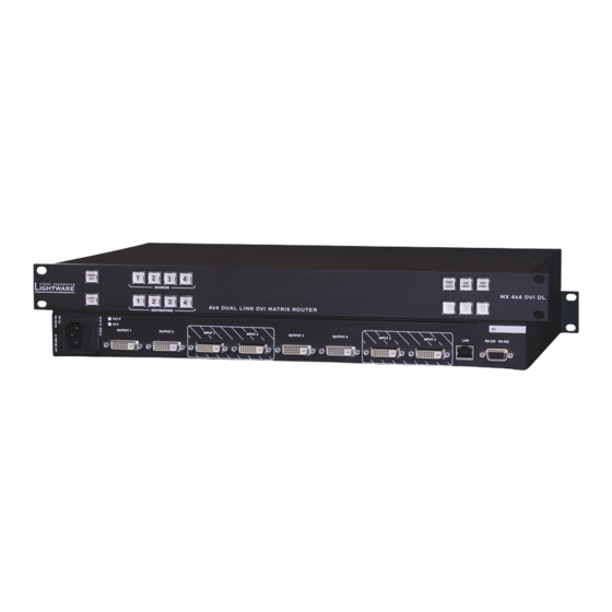
MX4x4DVI-DL User’s Manual Front Panel view CONTROL LOCK Sources 1 to 4 Take/ Load Save Autotake Preset Preset OUTPUT LOCK Destinations 1 to 4 Disables or enables front panel operation. When red Control Lock illuminated, operations on front panel are prohibited. - Page 8 Rear Panel view Signal presence LED-s INPUT connectors 1 to 4 AC Power DC Power OUTPUT Connectors1 to 4 Ethernet RS 232/422 connector Fuse LED's control port port Standard IEC power connector. The router works with 90 to 264 AC Power Volts, 50 or 60 Hz power sources.
- Page 9 MX4x4DVI-DL User’s Manual RS 232/422 contr ol port Lightware MX 4x4 DVI and MX 4x4 DVI DL can be remote controlled through industry standard 9 pole sub-D female connector located on the rear panel of the unit. The router can be ordered with RS232 or RS422 control port.
- Page 10 DVI cables or active DVI repeaters/extenders. Fiber Cable pow ering As special feature MX4x4DVI and MX4x4DVI-DL on DDC +5V output (pin 14 on output connectors) is able to supply 500 mA current to power fiber optical DVI cables.
-
Page 11: Edid Management
EDID readout failure or missing EDID the source will not output DVI video signal. MX4x4DVI and MX4x4DVI-DL provides an advanced EDID Management feature with advanced functions that helps system integration. The built in EDID Router stores and emulates 100 EDID data and all monitor's EDID's that are connected to the output connectors. -
Page 12: Front Panel Operations
Operation POWER Connect the power cord to the router’s IEC standard power input connector. The unit is immediately powered on when the power cord is connected to the AC source. The router does not have a power switch, it remains powered on, until AC line voltage is present. - Page 13 MX4x4DVI-DL User’s Manual SWITCHING Creating a connection or multiple connections in TAKE mode First press and release the selected source button. The pressed source button and all destination buttons which are currently connected to this source will light up. The dark remaining destination buttons are not connected to this source.
-
Page 14: Save Or Load Presets
"no signal" message or automatically will turn off. SAVE or LOAD PRESETS MX4x4DVI and MX4x4DVI-DL has 4 front panel programmable presets. Each preset stores a configuration regarding all input connections for all outputs. All presets are stored in a non volatile memory, the router keeps presets even in case of power down. - Page 15 MX4x4DVI-DL User’s Manual Loading a Preset in AUTOTAKE mode Press and release LOAD PRESET button. Press and release the desired source (memory address) button (source 1 to 4). Now the selected preset is loaded. Info Loading a preset always modifies all output states.
- Page 16 OUTPUT LOCK Using the router there is a possibility to lock a destination. This feature prevents an accidental switching to the locked destination in case of important signal. Locking a destination means, that no input configuration can be changed or deselected on that particular destination.
- Page 17 1. Changing and viewing protocols MX4x4DVI and MX4x4DVI-DL is equipped with multiple router protocols. Switch the router in TAKE mode if used prevoiously in AUTOTAKE mode by pressing TAKE button for 2 seconds. ( TAKE will not light continuously)
- Page 18 Control commands: Legend : input number in 2 digit ASCII format (01,05,07 etc.) output number in 2 digit ASCII format CrLf = Carriage return, Line feed (0x0D,0x0A) space character (0x20) notes: From firmware version 1.13 one digit input, output, and preset numbers are accepted, characters are case-insensitive 1.
- Page 19 MX4x4DVI-DL User’s Manual 4. View connection on all outputs ( Audio / DVI / RGB / SDI / Video) Command {VC} Response (ALL O1 O2 O3 O4 O5 O6 O7 O8)CrLf Description: Response length depends on the number of outputs installed in the router.
- Page 20 8. Save preset to the specified memory position ( Audio / DVI / RGB / SDI / Video) Command {$zz} Response (SPRzz)CrLf Description:Save current ties to preset zz. Example:Save current connections to preset memory 7. Command {$07} Response (SPR07)CrLf 9. Load preset from the specified position ( Audio / DVI / RGB / SDI / Video) Command {%zz} Response...
- Page 21 MX4x4DVI-DL User’s Manual 12. View Firmware version ( Audio / DVI / RGB / SDI / Video) Command Response (FIRMWARE_VERSION)CrLf Example: Command Response (FW:1.11)CrLf The connected router has a firmware version of 1.11. 13. Error responses ( Audio / DVI / RGB / SDI / Video)
-
Page 22: Installing Matrix Controller
Software control - Lightware Matrix Controller The unit can be controlled using Lightware Matrix Controller from a PC computer or Laptop through RS 232 or Ethernet port. INSTALLING MATRIX CONTROLLER Info Windows firewall should be switched off to enable the IP search feautre! - Page 23 If you want to create desktop icon click Yes in the next pop-up window: After finishing the installation of Lightware Matrix Controller the following message appears: To run Lightware matrix control software find and click from Start menu- >Programs->Lightware->LW_matrix_controller_vXXX.jar from desktop ikon (if this option was selected) via shortcut: To uninstall the control software double click on: Start menu ->Programs-...
-
Page 24: Using Lightware Matrix Controller
After starting the Lightware Matrix Controller, it automatically searches for Lightware devices connected to the LAN. If finds one picks its IP address and puts into the Comm Port menu. If there are no matrix switchers connected to the PC only comm ports will be shown in this menu. - Page 25 MX4x4DVI-DL User’s Manual MENU Description Matrix Controller contains following menus and submenus: LW Matrix Controller File -Synchronize matrix -Add new IP address -Exit View -Edid router Comm Port -Serial ports -IP addresses Help File menu File menu contains 3 items:...
- Page 26 More than one units can be connected to one Local Area Network HELP menu After a successful connection to a Lightware router all identifying information is shown under the Help menu. The connected matrix router’s name (MX8x8DVI_PRO), installed firmware revision (2.1.1) and serial number (format: year and week of production, and the serial...
-
Page 27: Save Preset
PRESET operations Preset operations can be done via the right panel named PRESET. Each Lightware matrix switcher has 32 preset memories, that can be loaded and saved any time. Front panel Preset operations effect only the first 8 preset memories, all others from 9 to 32 are available only via Matrix Controller software. - Page 28 RENAME a preset: Each preset has its own label (by default: Preset1..Preset32) which can be renamed. To modify these labels right-click on the preset list. The following window appears: Example: Select Preset3 and type the new preset name "new label", and click rename. The new name appears in the list.
-
Page 29: Edid Management: Using Edid Router
To provide proper EDID data for DVI sources MX 8x8 DVI PRO has an advanced built in EDID router, that can manage the emulated EDID on it’s all inputs indpendently. EDID can be managed using Lightware Matrix Controller software from a PC computer or Laptop through RS232 connection or Ethernet port. - Page 30 About EDID router EDID router contains a 116 block non volatile memory bank. EDID List is structured as follows: 1..50 ..............Factory Preset EDID list 51..100 ............User programmable memories 101..108 ( DVI_OUT_1...8) ......Attached monitor’s EDID list 109..116 ( DVI_IN_1...8).......emulated EDID at input conenctors Info The first 50 EDID (1…50 inclusive) are factory preprogrammed and cannot be modified.
-
Page 31: Control Software
If you want to connect via ethernet then you can also find IP address(es) in this drop-down menu. No IP addresses will be shown if no Lightware LAN enabled matrix switcher is connected to the same network as the PC. - Page 32 After the MATRIX CONTROLLER found the hardware a button matrix should appear. Select View->EDID router window. Info After a successful connection all identifying information is shown under the Help menu. Version 1.0 Page 32 / 43...
- Page 33 MX4x4DVI-DL User’s Manual The EDID ROUTER window appears and the software starts to synchronize EDID list with the Matrix switcher. After synchronization process the current status of the MATRIX SWITCHER EDID are shown on the two text area. The Emulated EDID window contains the resolutions and the vendor names of the EDID reported to the PC for each input separately.
- Page 34 EDID menu EDID menu contains 1 section: Syncronize EDID Selecting Synchronize EDID menu the Lightware Matrix Controller (PC) software rereads all EDID information from the connected MATRIX SWITCHER. While normal operation it is not necessary to use this menu item because the MATRIX SWITCHER always automatically reports every status change.
- Page 35 MX4x4DVI-DL User’s Manual Change emulated EDID at one or all inputs All EDID are enumerated in the switch EDID list. If you want to modify the current emulated resolution you can select one from this list. There is static EDID emulation or dynamic EDID emulation.
- Page 36 Select the output ( or ALL outputs) where the desired EDID will be emulated Press TAKE button. Now the EDID has been changed on selected input(s). After selecting a new EDID from the switch EDID list, selecting a output (or the ALL item) and pressing the TAKE button the MATRIX SWITCHER will modify that (or all) input(s) EDID.
- Page 37 MX4x4DVI-DL User’s Manual Learn EDID from attached display device The MATRIX SWITCHER can learn the EDID from the connected display device and store it in one of user programmable memory. All EDID is enumerated in the „Learn monitor EDID at output” list according to the router’s outputs.
- Page 38 Download EDID from file to memory The MATRIX SWITCHER is able to learn and store EDID from attached PC computer. EDID is stored in *.dat files. Select File-> Download EDID from file to memory. In the pop-up window browse your hard drive to find EDID file. The software checks if the selected file is a valid EDID file, than continue with step 3.
-
Page 39: Error Messages
MX4x4DVI-DL User’s Manual ERROR Messages During remote operation there may happen some trouble with the communication. This cases the Matrix Controller software displays error messages on the screen. Below there are listed the error messages. Unable to open Socket to the Server!!! Trigger: More than one user tries to access the router via LAN. -
Page 40: Firmware Upgrade
Firmware upgrade The unit can be upgraded with new firmware versions via RS232 port using a PC computer or Laptop. Please contact Lightware for the latest firmware version at sales@lightware.hu Before upgrading the new firmware, run the " LW_matrix_bundle.exe " wich installs the current "... -
Page 41: Specifications
MX4x4DVI-DL User’s Manual Specifications Inputs DVI input signals ..................4x DVI-D Connectors ................24 pole DVI-D digital only Auto equalization: ....................No Input cable equalization: ..................No EDID Management .............Yes for each input connector Signal Data rate: ...........all between 25 Mbps and1.65 Gbps /colour Channels: ............1x TMDS Clock + 6x TMDS Colours... - Page 42 Control Front Panel ..................YES, buttons Serial Port ............9pole Dsub Female RS232 or RS422 Baud rate ............9600 Baud, 4 bit, 1stop bit, no parity LAN ........TCP/IP Ethernet 10Base-T or 100Base TX Auto-Sensing General Power ..............100-240 V AC 50/60 Hz 1.4..1.0 A Compliance ......................CE EMI/EMC ................EN 55103-1, EN 55103-2 Safety ....................EN 60065 Class I...
- Page 43 MX4x4DVI-DL User’s Manual Production Quality Model name Serial number Date of manufacture Checked 1. Hardware Card BIOS Card BIOS MX 4x4 DVI CD ROM EDID Router Control P MAC ADDR IP ADDR Subnet Mask 2. Final check GND/EARTH Inputs +3.3V & +5V...
Need help?
Do you have a question about the MX4x4DVI and is the answer not in the manual?
Questions and answers