Table of Contents
Advertisement
Quick Links
Advertisement
Table of Contents

Related Manuals for GRAPHTEC CS400


Summary of Contents for GRAPHTEC CS400
- Page 1 400/300 COLOR IMAGE SCANNER USER’S MANUAL MANUAL NO. CS400-UM-152...
-
Page 3: Conventions Used In This Manual
TO ENSURE SAFE AND CORRECT USE • To ensure safe and correct use of your Image Scanner, read this Manual thoroughly before use. • After having read this Manual, keep it in a handy location for quick reference as needed. •... -
Page 4: Safety Precautions
Unplug the power • Request repair by contacting your sales representa- cord from the socket tive or nearest Graphtec vendor. • Never try to perform repair yourself. Repair work by inexperienced personnel is extremely danger- ous. - Page 5 Safety Precautions (Continued) WARNING Do not connect the scanner to a non-rated power supply. • Use of a different supply voltage may result in a fire hazard or electrical shock. Prohibited CAUTION Be sure to ground the earth terminal. • Unless the scanner is grounded, the operator could suffer an electrical shock in case of current leakage.
- Page 6 Safety Precautions (Continued) CAUTION Be careful not to damage the power cord or the interface cable and never use a damaged cord or cable. • Do not use unnecessary force to bend, pull, twist, or bind the cord and cable, place a heavy object Never damage or on them, nor remodel them.
- Page 7 Safety Precautions (Continued) CAUTION Do not install, use, or store the scanner in a loca- tion that does not meet the specified temperature and humidity ranges. • Such location may impair the scanner’s perform- ance and cause the scanner to malfunction or break down.
- Page 8 Safety Precautions (Continued) CAUTION Do not use sharp, pointed articles on the scanner. • Such action may impair the scanner’s performance and cause the scanner to malfunction or break down. Prohibited Do not exert pressure on the scanner. • Such action may impair the scanner’s performance and cause the scanner to malfunction or break down.
-
Page 9: Introduction
INTRODUCTION Thank you for purchasing the CS400/300 Image Scanner. The CS400/300 is capable of accurately performing high-speed scanning of documents ranging in size from ISO A4 to ANSI E. This User’s Manual describes how to operate the CS400/300, and also includes usage precautions. - Page 10 (Refer to Section 5.1, “Opening and Closing the Top Cover”.) Scanner Warm-up A warm-up period is not usually required for the CS400/300. However, if you plan to scan a color document (in particular a document with many light colors), we recommend that you allow the CS400/300 to warm up for 10 minutes before scanning the document.
-
Page 11: Table Of Contents
Contents TO ENSURE SAFE AND CORRECT USE ............ Conventions Used in This Manual ................Description of Safety Symbols ................. Safety Precautions ....................Introduction ......................... 1. OVERVIEW ......................Features ......................1-1 Unpacking the Scanner ................. 1-2 2. PREPARATION ....................Assembling the Scanner ................2-1 Part Names and Functions ................ - Page 12 6. TROUBLESHOOTING PROCEDURES ............. The Scanner Is Turned On But Doesn’t Operate at All ......6-1 The Scanner Operates Improperly After Connection to the Computer ..6-1 The Control Panel’s Red ERROR Lamp Is Lit ........... 6-2 The Control Panel’s Red ERROR Lamp Is Flashing ......... 6-2 The Document Isn’t Properly Fed to the Initial Scanning Position ...
-
Page 13: Overview
Compatible with document sizes from ISO A4 up to ANSI E Capable of color and grayscale scanning Capable of scanning in color (24-bit color*, 8-bit color) or grayscale (256 shades) * CS400 only Capable of reading long-axis data Scanning of long-axis images is supported. -
Page 14: Unpacking The Scanner
After unpacking the Image Scanner, check its outer casing and check that the standard accessories listed below are all present. If you detect a surface flaw or a missing accessory, please promptly contact your sales representative or nearest Graphtec vendor. Standard Accessories Power cable User’s Manual... -
Page 15: Preparation
(2) Attach the center bar to the side stays temporarily using the four screws provided. Side stay Side stay Center bar Groove Caster Caster Attach the center bar loosely. Tighten the bolts securely after the scanner unit has been mounted on the stand. CS400/300 2 – 1... - Page 16 Side cover Rubber feet Fixing plate Fixing plate Coin screw Coin screw Center bar Notch Fixing plate Groove (4) Secure the side stays in place by tightening up the four center bar fixing screws (see (2) above). 2 – 2 CS400/300...
- Page 17 Screw A Screw A Frame 3 (7) Always ensure that you remove the cushion material that is included below the document hold-down unit before using the product. (Refer to Section 5.1, “Opening and Closing the Top Cover”.) CS400/300 2 – 3...
-
Page 18: Part Names And Functions
Document guides Use these guides to determine the position of a document when you load the document. These guides are a sliding type for the CS400 and a magnetic type for the CS300. Control panel Use the keys to operate the scanner and the LEDs to monitor the operating status. - Page 19 Used to connect the IEEE 1394 interface cable. The USB and IEEE 1394 connectors cannot be used at the same time. Do not connect both the USB and IEEE 1394 cables to a computer, or to two separate computers, at the same time. CS400/300 2 – 5...
- Page 20 Feeds the document toward you. When this key is pressed in Scan READY status, the Scan READY status is cancelled and the document is ejected toward the front of the scanner. STOP key Compulsorily stops scanning of the document. 2 – 6 CS400/300...
-
Page 21: Attaching The Document Support Wires
Attaching the document support wires (1) Insert one end of the document support wire provided into the slot at the rear of the scanner. (2) Squeeze the document support wire, and insert the other end. CS400/300 2 – 7... - Page 22 (3) Press down on both sides of the document support wire. (4) Attach the other document support wires in the same manner. Detach the document support wires when moving or packing the scanner. Squeeze softly and lift them to detach. 2 – 8 CS400/300...
-
Page 23: Preparing To Operate The Scanner
USB 2.0 interface, please contact your sales representative or nearest Graphtec vendor for information on supported add-on cards. Graphtec does not guarantee correct scanner operation with every IEEE 1394 computer interface or add-on card. Please contact your sales representative or nearest Graphtec vendor for information on supported add-on cards. -
Page 24: Connecting The Scanner To A Power Supply
Ensure that the scanner’s Power switch is in the Off position. Make sure that your scanner is properly grounded. If it is not grounded, there is a possibility that noise will cause incorrect operation, or that the scanned image may be distorted. 3 – 2 CS400/300... - Page 25 When the scanner has been initialized, the POWER lamp lights up. When resetting the scanner by turning it off then back on again, wait at least five seconds before turning it back on. CS400/300 3 – 3...
-
Page 26: Connecting The Scanner To A Computer
(1) Ensure that you have a USB 2.0 interface cable that works with your computer. Plug the USB 2.0 interface cable into the USB connector socket situated on the right-hand side of the scanner unit. USB connector To the computer USB 2.0 interface cable 3 – 4 CS400/300... - Page 27 Plug the IEEE 1394 interface cable (6-pin) into the IEEE 1394 connector socket situated on the right-hand side of the scanner unit. IEEE 1394 connector To the computer IEEE 1394 interface cable IEEE 1394 (6-pin) connector CS400/300 3 – 5...
-
Page 28: Installing The Driver Software
The following procedure assumes that you are using the CS400 as part of your system, and that you are using the USB interface. If you are using the IEEE 1394 interface, GRAPHTEC CS400-10 IEEE 1394 SBP2 Device will be displayed where CS400-10 is displayed when the USB interface is used. - Page 29 (6) Select the check box entitled “Specify a location” and click Next. Click Browse and select the DRIVER folder in the CD-ROM drive or enter a CD-ROM drive name and \DRIVER using the keyboard. Example: For drive E, enter “E:\DRIVER.” CS400/300 3 – 7...
- Page 30 Click Yes to continue the installation. (9) The screen shown below is displayed when the wizard has finished installing the driver. Click the Finish button. (10) The Windows 2000 Desktop appears and the Scanner is acknowledged by the computer. 3 – 8 CS400/300...
- Page 31 The following procedure assumes that you are using the CS400 as part of your system, and that you are using the USB interface. If you are using the IEEE 1394 interface, GRAPHTEC CS400-10 IEEE 1394 SBP2 Device will be displayed where CS400-10 is displayed when the USB interface is used.
- Page 32 (7) The screen shown below is displayed when the wizard has finished installing the driver. Click the Finish button to close the “Welcome to the Found New Hardware” wizard. (8) The Windows XP desktop appears, and the scanner is recognized by the computer. 3 – 10 CS400/300...
-
Page 33: Checking The Interface Connection
3.5 Checking the Interface Connection For Windows 2000 The procedure outlined below assumes that the CS400 is connected in your system. Substitute CS300-10 for CS400-10 for guidelines as to how to use the CS300. (1) Launch the Control Panel using the Start menu. - Page 34 3. PREPARING TO OPERATE THE SCANNER For Windows XP The procedure outlined below assumes that the CS400 is connected in your system. Substitute CS300-10 for CS400-10 for guidelines as to how to use the CS300. (1) Launch the Control Panel using the Start menu.
-
Page 35: Installing The Scanning Master 21+ Application
3. PREPARING TO OPERATE THE SCANNER 3.6 Installing the Scanning Master 21+ Application The Scanning Master 21+ “OPS112” is a software application for using a Graphtec scanner to scan image data. Operating Environment Windows 2000 Professional/XP Professional/XP Home Edition Installation Procedure (The following steps are explained using the Windows 2000 windows.) -
Page 37: Loading A Document
Media Thicknesses Observe the following points when scanning a thick medium. • The CS400/300 cannot scan a document that is thicker than 1.5 mm. • When using the carrier sheet, ensure that the combined thickness of both the document and carrier sheet does not exceed 1.5 mm. - Page 38 The document is scanned in the standard paper size determined from the automatically detected document width. Automatic detection—ISO series Automatic detection—ANSI series Automatic detection—ARCH series Automatic detection—DIN series The document is scanned in the paper size of the respective series as determined from the automatically detected document width. 4 – 2 CS400/300...
- Page 39 Insert the document onto the document-scanning table face down so that it presses against the rollers evenly. How to use the document guides CS400 • Move the document guides to the left and right until they are adjusted to the document width.
- Page 40 (see Section 4.6, “Using the Carrier Sheet” for details). • Load the document in the center of the scanner, as the document may be fed in at an angle and not scanned correctly if it is significantly off-center. 4 – 4 CS400/300...
-
Page 41: Making The Document Hold-Down Unit Force Settings
• Always ensure that you check the lever status before using the scanner, because the modes may switch if the scanner has been subjected to a strong vibration as a result of being dropped or shaken. CS400/300 4 – 5... -
Page 42: Handling Documents According To Their Material And Thickness
• The end of the document is not scanned. Such problems may be avoided by taking the following corrective measures. • Lower the scanning speed. • Support the document at the front and the back of the scanner. 4 – 6 CS400/300... -
Page 43: Distance Correction
The values entered here must be within the range of the distance correction. (6) Click the OK button to calculate the correction value. The distance will be corrected the next time a document is scanned. CS400/300 4 – 7... -
Page 44: Using The Carrier Sheet
If this happens, set the document hold-down unit force setting to “High”. Transparent sheet (front surface) Target document (the surface to be scanned faces up) White surface (background surface) When handling the carrier sheet, be very careful not to scratch it or otherwise damage 4 – 8 CS400/300... -
Page 45: Daily Maintenance
90 degrees. Open levers Top cover (3) Close the top cover until the left and right latches on the top cover lock into position, making sure that you don’t get your fingers caught. CS400/300 5 – 1... -
Page 46: Cleaning The Document Hold-Down Unit
(5) Close the top cover as described in Section 5.1 “Opening and Closing the Top Cover”. Take care not to get your fingers caught in the cover. Scanning may be affected if the underside of the document hold-down unit becomes scratched or dirty. It must be cleaned when necessary. 5 – 2 CS400/300... -
Page 47: Cleaning The Image Sensors
(5) Close the top cover as described in Section 5.1 “Opening and Closing the Top Cover”. Take care not to get your fingers caught in the cover. Do not use a commercial cleaner for office equipment, a glass cleaner, or chemical solvents such as solutions containing alcohol. CS400/300 5 – 3... - Page 48 (unexpected white or black streaks in the data) due to scratches on the transparent contact plate or other reasons, please perform the calibration procedure (see Section 5.6, “Calibration”). If the scanning results do not improve after calibration, the transparent contact plate(s) will need to be replaced. 5 – 4 CS400/300...
-
Page 49: Cleaning The Paper Sensors
(4) Close the top cover as described in Section 5.1 “Opening and Closing the Top Cover”. Take care not to get your fingers caught in the cover. Use a cotton swab or something equally soft to gently wipe the paper sensors. Do not use any chemicals to clean the sensors. CS400/300 5 – 5... -
Page 50: Removing A Jammed Document
(4) If the document is jammed at the rear, remove the document from the inside by pulling it toward the rear. (5) Close the top cover as described in Section 5.1 “Opening and Closing the Top Cover”. Take care not to get your fingers caught in the cover. 5 – 6 CS400/300... -
Page 51: Calibration
• The calibration sheet is a paper product. Do not attempt to clean it with any type of liquid cleaner. • The calibration sheet is a consumable item. Replacement sheets can be purchased from your sales representative or nearest Graphtec vendor. Preparation and checks Recommended usage environment Monitor: 1024 ×... - Page 52 (4) Select the connected scanner and click the OK button. (5) Select Calibration on the Scanner menu. (6) Select All in Calibration and click the Execute button. (7) The following message is displayed. Insert the calibration sheet into the scanner as instructed. 5 – 8 CS400/300...
- Page 53 Check that there are no vertical streaks, such as white patches, in the scanned data. (Streaks occur when calibration is not performed correctly due to contamination by dust or dirt.) (13) If the data is normal, calibration is complete. Click the Close button and exit the Scanner Adjustment Program. CS400/300 5 – 9...
- Page 54 (17) Return to step (10) and verify the calibration results. If you perform the calibration procedure several times with no discernible results, there may be a problem with the scanner itself. In this case, please contact your Graphtec vendor. Color Correction Perform color correction if there is any discrepancy in color in parts of the scanned image even after you have calibrated the scanner.
- Page 55 For numbers 1 to 5, click the center of the upper left tile; for number 6, click in the center of the bottom right tile. Align the cursor crosshairs with the printed lines at the sides of the tile. Cursor lines (red) Align with the printed lines, then click. CS400/300 5 – 11...
- Page 56 (11) Click the Fit icon to display the entire image, and check whether there is any discrepancy in color. If there is no discrepancy, color correction is complete. Click the Close button. If there is still some color discrepancy after performing Color Correction, repeat steps (6) through (11). 5 – 12 CS400/300...
-
Page 57: Troubleshooting Procedures
The “Model Setup” settings are not Set the “Model Setup” settings in Scanning correctly set in Scanning Master 21+. Master 21+ to “CS400-10 or CS300-10.” For details, refer to the Scanning Master 21+ User’s manual. Is the “Connection Method” of the Ensure that the “Connection Method”... -
Page 58: The Control Panel's Red Error Lamp Is Lit
Remedy A hardware error at the ROM, RAM, etc. An internal error has occurred. Contact your occurred during the scanner’s self-test. sales representative or nearest Graphtec vendor. 6.4 The Control Panel’s Red ERROR Lamp Is Flashing Cause Remedy The scanner was turned on with a docu- Open the cover and remove the document (see ment left loaded inside it. -
Page 59: After Scanning, Image Data Becomes Black Or White
The transparent contact plates over Clean the transparent contact plates (see the image sensors are dirty Section 5.3, “Cleaning the Image Sensors”) The carrier sheet is not used with Use the carrier sheet. transparent or translucent documents. CS400/300 6 – 3... -
Page 60: The Input Image Data Is Incorrectly Aligned
Moreover, fine adjustment to correct such deviation can be performed using the driver software if the deviation causes are overlapped or missing data. Overlapped data Original document Data overlaps Missing data Original document Data is missing Deviation due to scanner specifications Original document Deviation caused by specifications 6 – 4 CS400/300... - Page 61 Sensor 1 Sensor 4 Sensor 2 Markings on the document scanning table Document feed direction Example: CS2000 Because the document is loaded face down, Sensor 1 is the leftmost sensor in the driver software’s display windows. CS400/300 6 – 5...
-
Page 62: Smudges Not Appearing In The Original Document Appear In The Scanned Data
(Scanning Master 21+) provided with for a document of a different paper type. your scanner, select the Distance Correction The scanning precision varies according function to adjust the precision. to the type of document. 6 – 6 CS400/300... -
Page 63: Stripes Or Moire Patterns Which Are Not In The Original Document Appear In The Scanned Data
Run the “Scanner Adjustment Program” deteriorated. (see Section 5.6, “Calibration”), and perform calibration. You are using a carrier sheet with a color Don’t use the carrier sheet. document. Or, set the document hold-down unit force to “High”. CS400/300 6 – 7... -
Page 64: The Document Cannot Be Fed Correctly
6.17 The Document to be Scanned is Too Short or Too Long in Length Cause Remedy Automatic document size detection was Load the document again. Select a user-defined used, but failed. document size or standard size if the same problem occurs after a number of retries. 6 – 8 CS400/300... -
Page 65: Appendix A. Optional And Miscellaneous Items
APPENDIX A. OPTIONAL AND MISCELLANEOUS ITEMS APPENDIX A. OPTIONAL AND MISCELLANEOUS ITEMS Optional items can be obtained from your sales representative or nearest Graphtec vendor. Optional items Code Item name Software to upgrade OPS112 Scanning Master 21+ to OPS115 Scanning... -
Page 67: Appendix B. Standard Specifications
APPENDIX B. STANDARD SPECIFICATIONS APPENDIX B. STANDARD SPECIFICATIONS Item CS400 CS300 Document size ANSI E to ISO A4 Maximum width: 1090 mm; minimum width: 210 mm Effective scanning area Width : 1016 mm (centered) Length : 16 m Guaranteed scanning ×... -
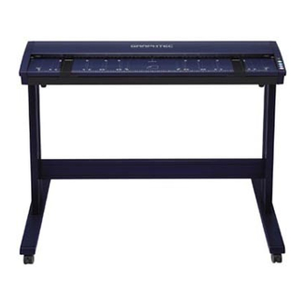
Page 69: Appendix C. External View
APPENDIX C. EXTERNAL VIEW APPENDIX C. EXTERNAL VIEW External Dimensions 1205 Note: The diagrams are of the CS400 model. Unit : mm Dimensional precision error : ± 5 mm CS400/300 C – 1... - Page 71 Troubleshooting .......... 6-1 FORWARD key ........... 2-6 USB connector ........... 2-5 Usage precautions ........viii IEEE 1394 connector ......... 2-5 Image sensors, cleaning the ..... 5-3 Interface ............1-1 Warmup ............viii Missing data ..........6-4 CS400/300 Index – 1...
- Page 73 The specifications, etc., in this manual are subject to change without notice. CS400-UM-152 January 26, 2004 1st edition-01 GRAPHTEC CORPORATION...
Need help?
Do you have a question about the CS400 and is the answer not in the manual?
Questions and answers