jablotron MAESTRO JA-65 Installation Manual
Alarm system
Hide thumbs
Also See for MAESTRO JA-65:
- Installation manual (31 pages) ,
- Installation manual (17 pages)
Table of Contents
Advertisement
Quick Links
Download this manual
See also:
Installation Manual
Advertisement
Table of Contents

Related Manuals for jablotron MAESTRO JA-65


Summary of Contents for jablotron MAESTRO JA-65
- Page 1 JA-65 “MAESTRO” Alarm system Installation manual...
- Page 2 This manual is valid for control panel model (control panel board) (telephone communicator board). The use of Comlink Windows v. 53 software or higher is required for this control panel and can be obtained from our home page at WWW.JABLOTRON.CZ...
-
Page 3: Table Of Contents
Contents: 1. Architecture of the control panel 2. Configuration of the control panel 3. Control panel installation 3.1. Power cable wiring 4. Antenna of the JA-65R module 4.1 Rubber antenna use in the control panel 4.2 External antenna use 5. Connection of a telephone line to the JA-65X module 6. -
Page 4: Architecture Of The Control Panel
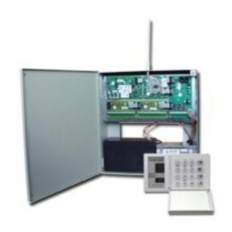
This product is to be installed by professional installers only. The manufacturer assumes no liability for damages caused by incorrect installation or improper use of this system. 1. Architecture of the control panel The JA-65 "Maestro" is a fully programmable control panel with building block architecture. This allows the JA-65 to be tailored to particular installation requirements. -
Page 5: Configuration Of The Control Panel
2. Configuration of the control panel The metal case of the JA-65K control panel is shipped from the factory with a built-in power supply unit and the main board. To be able to work as an alarm system, it should be equipped with interface modules (R, H, X) in the following way: •... -
Page 6: External Antenna Use
JA-65 and the maximum length of the cable can be 500 meters. We recommend use of a CT-04 cable and RJ-44 (Jablotron) crimping connectors to make the keypad cables. The digital data is also available on the terminals: see the following description. -
Page 7: The Ja-65H Hard Wired Input Module Terminals
available on the JA-65H hard-wire modules for easier wiring. All +U terminals are connected in parallel to the +U terminal of the main board. 7. The JA-65H hard wired input module terminals Up to two 65H modules can be used in the control panel. The module with its cable connected directly to the main board provides zone inputs 1 to 8. -
Page 8: Wiring Of The Ja-60 Keypad(S)
8. Wiring of the JA-60 keypad(s) The system can be programmed and operated by JA-60E keypad(s). As a maximum, 5 keypads can be wired to the control panel. The keypads can either be wired by cables equipped with modular jacks to connectors K4 and K5 or by standard cables to terminals 1,2.3 &... -
Page 9: Control Panel Programming
• Switch on the AC power • The keypad will display a "P", confirming that the system is in the programming mode (for system setting, enrollment of wireless items and for testing). Note: if „P“ is not displayed, the control panel is not in the factory default setting. Perform a Factory default reset. (See section 17). 12. -
Page 10: Enrollment (Teaching) Of Wireless Items
12.1. Enrollment (teaching) of wireless items enter: 1 If the control panel has a 65R module, as a maximum 16 wireless detectors and 8 controllers (remote controls & keypads) can be enrolled to the control panel. A wireless siren and an additional JA-60 or JA-65 control panel (a subsystem) can be enrolled as well. -
Page 11: Alarm Duration
12.4. Alarm duration sequence: 2 2 x The alarm duration can be selected from 1 to 8 minutes (or 10 seconds or 15 minutes) entering 22x (where x represents time in minutes, for x=0 the duration will be 10 seconds, for x=9 the duration will be 15 minutes). Example: to select an alarm duration of 5 minutes, enter 225 Factory default setting is 4 minutes 12.5. -
Page 12: Reset Enabled
options: 2 7 1 checking enabled 2 7 0 checking disabled Factory default setting: checking disabled Note: in some locations with a strong radio interference (near radar, TV or radio station etc.) the communication can be jammed periodically. The control panel can detect such a strong interference as a temporary loss of communication with an item. -
Page 13: Hard Wired Siren Alarm Enabled
12.13. Hard wired siren alarm enabled sequence: 3 2 x The SIR siren output is activated when any alarm is triggered (except silent Panic alarm). The siren indication can be disabled with this parameter. options: 3 2 1 siren enabled 3 2 0 siren disabled Factory default setting: siren enabled... -
Page 14: Wireless Siren Alarm
12.19. Wireless siren alarm sequence: 3 8 x The wireless siren alarm function can be disabled with this parameter. This setting will have no influence on the outdoor wireless siren chirp sound function if enabled in the siren. This setting has effect only when the control panel is equipped with a 65R module: options: 3 8 1... -
Page 15: Addressing Of Wireless Controllers To Sections
Notes: • If the control panel is not split, this setting has no effect. • Master code (MC) can not be addressed. If the system is split, the use of MC will arm all sections if no section is armed or it will disarm all sections if any is armed. -
Page 16: Real Time And Date Setting
12.27. Real time and date setting sequence: 4 hh mm dd MM YY The control panel has a built in real time clock. All events are stored to the event memory including the time of the event. The clock should be set after the installation is completed. Time Setting: 4 hh mm dd MM YY where hh = hours (24 hr. -
Page 17: Telephone Number Entering
2 messages 951 = YES 950 = NO Triggering of the dialer with a Technical alarm see 14.5 991 = YES 990 = NO Telephone line checking enabled xx...x = tel. number, y = Store telephone numbers for voice message 7xx..x F y memory 1 to 4, pause = F0 x..x = provider tel. -
Page 18: Voice Message(S) Recording
14.2. Voice message(s) recording sequence: 8 4 The existing message(s) can be played by momentarily pressing the push button on the 65X module. To record your voice message, enter 84 on the keypad and then press and hold the push button on the 65X module while talking into the 65X microphone (max. -
Page 19: To Enable A Remote Computer To Dial In
15. To enable a remote computer to dial in When the user or installer wants to dial in to the installation from their JA-60U modem equipped computer (see 20.), the following parameters should be programmed in the 65X control panel’s telephone dialer. The most convenient programming of the dialer is via a connected PC using the Comlink software (see 19). -
Page 20: Monitoring Station Communication Setting
Internal structure of the CID protocol is shown in the part 18.1. This protocol provides the most in-depth data for the monitoring station and its use is recommended by Jablotron. -
Page 21: Account Code Setting
• The pulse formats are not capable to report zero and numbers above 15. For this reason events in zone 16 or in a subsystem are reported to the Monitoring Station as events in zone 10. This means that from the point of view of the monitoring station zone 10 also covers zone 16 and the subsystem if used. -
Page 22: Phone Number Entering
16.5. Phone number entering sequence: 06 Monitoring station modem phone numbers can be stored by entering the following sequence: 0 6 x x ..x F y xx...x - Monitoring Station phone number (up to 16 digits) 1 for main phone number memory 2 for back up phone number memory Pause (3 sec.) can be inserted into the telephone number by entering F0. -
Page 23: Monitoring Station Report Code Table
18. Monitoring station report code table A two digit report code rc (00 to FFh) can be set for every event. If 00 is programmed as a report code, that event will not be reported. The major events group is marked by Rc. When formats 3/1 or 4/1/1 are used, only 16 of these major events are reported to the Monitoring Station. -
Page 24: Internal Structure Of Contact Id Protocol
18.1. Internal structure of Contact ID protocol The data in the CID protocol has following standardized structure: XXXX 18 Q XYZ 01 CCC where XXXX is the account code of the installation, 18 is the code identification (identical for all events), Q is a number from 1 to 3, XYZ is the event number, 01 is the subsystem number, CCC event source details (see the table below). -
Page 25: Personal Computer Interface With Pc-60A
19. Personal Computer Interface with PC-60A The JA-65 system can be connected to a Personal Computer (PC) locally, using the PC-60A interface cable. It is also possible to dial into the system from a remote PC using the JA-60U modem (see section 20). Comlink software is available for Windows system. User can check and operate the JA-65 system easily via their PC, can read complete events memory with all details, can view the map of the installation (seeing topical triggering of the detectors) etc. -
Page 26: Remote Access To The System
20. Remote access to the system It is possible to dial in to the JA-65 control panel from a remote computer equipped with a JA-60U modem and Comlink SW. The remote access is protected by an 8 digit access code stored in the JA-65 control panel (see 15.2.). After the modem dials in to the remote control panel, the Comlink SW provides identical features as if connected locally (see 19). -
Page 27: Possibilities To Extend The System
The following description includes the basic assortment of accessories. Jablotron is systematically introducing new and improved items to the market. You can get the most current information from your distributor or you can visit Jablotron’s Internet home page at: www.jablotron.com 24.1. - Page 28 PC interface cable PC-60A - can be used to connect the control panel to a serial port (COM) in your computer. Suitable SW, ComLink, is provided on a floppy disk or you can visit Jablotron’s Internet home page at: www.jablotron.com download a beta version of it.
- Page 29 GS-130, GS-133 Gas leak detectors - trigger a Fire alarm when any combustible gas is detected (natural gas, city gas, propane, butane etc.). The detector has a built in siren and an output relay. The relay, for example, can be wired to an electrical valve to turn off the gas supply when a leak is detected.
-
Page 30: Control Panel Specifications
25. Control panel specifications: Electrical Power 110-230 VAC, (built in electronic power supply), supervised Backup battery 12 V, from 1.3 to 7 Ah (external up to 40 Ah), supervised, not included Backup power output for wired items 13VDC, max. 1.5A, supervised Hard-wired inputs module 65H: 8 input zones, up to two 65H modules can be used (16 zones) Zone input triggering...
Need help?
Do you have a question about the MAESTRO JA-65 and is the answer not in the manual?
Questions and answers