Table of Contents
Advertisement
Quick Links
Download this manual
See also:
Instruction Manual
Advertisement
Table of Contents

Related Manuals for Digimerge VB300 SERIES


Summary of Contents for Digimerge VB300 SERIES
- Page 1 DIGIMERGE-BLADE MICRO FORM FACTOR, H.264 DIGITAL VIDEO RECORDER INSTRUCTION MANUAL English Version 1.0 MODELS: VB300 SERIES www.digimerge.com © Copyright 2008 Digimerge Technology Inc.
- Page 3 H.264 compression, Quadplex functionality, Smart Video detection, and full POS/ATM* and Web browser support. To learn more about the Blade DVR, and to learn about our complete range of accessory products, please visit our website at: www.digimerge.com CAUTION RISK OF ELECTRIC SHOCK DO NOT OPEN CAUTION: TO REDUCE THE RICK OF ELECTRIC SHOCK DO NOT REMOVE COVER.
-
Page 4: Important Safeguards
Important Safeguards In addition to the careful attention devoted to quality standards in the manufacture process of your video product, safety is a major factor in the design of every instrument. However, safety is your responsibility too. This sheet lists important information that will help to assure your enjoyment and proper use of the video product and accessory equipment. - Page 5 Service 13. Servicing - Do not attempt to service this video 19. Cleaning - Unplug the video product from the wall equipment yourself as opening or removing covers outlet before cleaning. Do not use liquid cleaners or may expose you to dangerous voltage or other aerosol cleaners.
-
Page 6: General Precautions
However, it is imperative that the user follows this manuals guideline to avoid improper usage which may result in damage to the unit, electrical shock and fire hazard injury In order to improve the feature functions and quality of this product, the specifications are subject to change without notice from time to time. www.digimerge.com... -
Page 7: Table Of Contents
Table of Contents Features ............. 4 Getting Started . - Page 8 RECORD ............. . 33 RECORD SETUP .
- Page 9 How do I enable port forwarding? ..........64 Appendix 4: Setting Up DDNS Service .
-
Page 10: Features
Features • Micro form factor • H.264 compression • Record, playback, backup, and network simultaneously • Mulitple input methods: Remote Control, Front Panel, external keyboard (not included) and PS/ 2 mouse (not included) • Slim 2.4” internal hard drive • Intelligent Search and Playback—playback only video recorded by motion detection •... -
Page 11: Getting Started
Getting Started Getting Started The system comes with the following components: 1 X MOUNTING PLATE 1 X BLADE DIGITAL VIDEO RECORDER 1 X POWER ADAPTOR 1 X CAMERA OCTOPUS CABLE* 1 X REMOTE CONTROL 1 X DVI CABLE 4 X SCREWS 2 X RCA "Y"... -
Page 12: Basic Setup
Basic Setup Basic Setup The Blade DVR is designed to mount securly to the back of LCD monitors with a VESA mount. However, if desired, you can also leave the Blade DVR in a standard horizontal position. ATTENTION: You can only mount the Blade DVR to an LCD monitors with a VESA mount and an independent stand. -
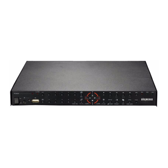
Page 13: Front Panel
Front Panel Front Panel † 1. Power Button: Press to turn the Blade DVR ON/OFF 2. Mini-Jack (2.5mm): Connect an IR module extension cable. 3. LEDs: System power and Alarm LED indicators. 4. Channel Buttons: Press to view channels 1~9; press +10 then 0~6 to select channels 10~16*. 5. -
Page 14: Front Panel (Cont'd.)
Front Panel (cont’d.) Front Panel (cont’d.) 17. SEQ: Start/stop Auto-Sequence mode; increases, decrease, or changes values of selected menu options. 18. Freeze: Press to start Freeze mode; press to focus control of PTZ; increases, decrease, or changes values of selected menu options. 19. -
Page 15: Rear Panel
Rear Panel Rear Panel 1. Camera In: Camera input ports for Camera Octopus Cables*. 2. Video: BNC port for a Spot Monitor. 3. Audio In: Two 3.5" RCA jacks for audio input (Y-cables included); the left port is for audio channels 1 and 2, the right port for audio channels 3 and 4. -
Page 16: Remote Control
Remote Control Remote Control REMOTE CONTROL ID: Press buttons 1~4 to match Remote Control ID entered in the System Menu. IRIS-/+, Z -/+: • IRIS -/+: Press to open/close of a PTZ camera*; press for Frame-by-Frame (field by field) playback •... -
Page 17: Mouse Control
Mouse Control Mouse Control Control scheme for a PS/2 mouse (optional). 1. Left-Button: While in a split-screen display mode. double click an individual channel to view it in full-screen; double click again to return to the split-screen display mode. While navigating menus, click to slect a menu option;... -
Page 18: Using The System
Using the System Using the System Note: Make sure all cameras and cables are properly connected prior to powering on the system. Starting the System Press the POWER button on the front panel to turn the system ON/OFF. At startup, the system performs a basic system check and runs an initial loading sequence.* After a few moments, the system loads a live display view. -
Page 19: On-Screen Display
Using the System On-Screen Display The system shows the following for all of the display views: Figure 3.0 Main system display 1. HDD percentage: The percentage of free space remaining on the hard disk. Other system functions, such a s Freeze, Auto-Sequence, and Playback will display in this top-left corner. 2. -
Page 20: Display Views
Using the System Display Views You can view connected cameras on the system in various configurations. Press the button on the remote control to change between display views. 9-channel* Single channel (full-screen) Quad * 10-channel* 16-channel (grid) 7-channel* *Customize the layout for the five multi-screen display views from Main Menu>Screen>Multi Screen. -
Page 21: Additional Display Functions
Using the System Additional Display Functions The system includes Auto Sequence, Freeze, and Picture-in-Picture to help maximize your security needs. Auto Sequence Auto Sequence allows you to view all channels in sequence. You customize what display modes to include or exclude from Auto Sequence, including full-screen single channels and video loss channels. -
Page 22: Picture-In-Picture
Using the System Picture-in-Picture Monitor a second channel while in full-screen (single channel) mode using Picture-in-Picture (PIP). Figure 3.3 Picture-in-Picture display To enable PIP: 1. Press channel buttons 1~16 on the remote control to view the channel in full screen. 2. -
Page 23: Setting The Time
Setting the Time Setting the Time You should set the time on the system prior to doing any recording. You can set the time manually, or set the time according to an Internet server (Internet connection and DDNS service required). To set the date and time: 1. -
Page 24: Recording
Recording Recording By default, the system is set to immediately record video from connected cameras in Continuous Record Mode. Also, the system is set to record based on a certain Recording Schedule and Record Program. The system uses ten Record Programs that you can customize to best fit your needs. -
Page 25: Playback
Playback Playback View recorded video on the system through playback mode. Figure 5.0 Playback display view To begin playback: 1. Press the button on the remote control. The system will play the last 10 minutes of the most recently recorded video. 1. -
Page 26: Search
Search Search Search for recorded video data on the system according to the following: • Calendar Search • File Search • Search & Copy • Bookmark Search • Time Search • Text Search • Event Search • Log File • Block Search •... -
Page 27: Search & Copy
Search 4. During playback, you have access to the To use Search & Copy: following options: 1. Under SEARCH START TIME, press the buttons to select the year, month, • Press the Playback Buttons on the remote control to pause, fast forward, or day, hour, minute, and second, and then rewind video. -
Page 28: Time Search
Search TIME SEARCH EVENT SEARCH Use Time Search to search for recorded video Use Event Search to quickly search for date from a specific date and time. recorded video according to motion, alarm, or video loss events. Figure 6.3 Time Search screen Figure 6.4 Event Search screen To use Time Search: To use Event Search:... -
Page 29: Block Search
Search BLOCK SEARCH FILE SEARCH Use Block Search to search for recorded video Use File Search to search for video files saved according to blocks on the hard disk. to an external USB drive or USB flash drive (not included). Note: Block Search is recommended in case of a failure when using other search modes. -
Page 30: Bookmark Search
Search BOOKMARK SEARCH To use Bookmark Search: Use Bookmark Search to quickly search 1. From the SEARCH menu, select recorded video according to set bookmarks. BOOKMARK SEARCH and press the Note: You must have set bookmarks while button. in Playback mode in order to use Bookmark 2. -
Page 31: Text Search
Search TEXT SEARCH* LOG FILE Use the Text Search to find recorded data from Use the Log File to see a list of the activities a P.O.S. system. and events on the system. Note: You must connect a USB drive to the system in order to view log files. -
Page 32: Using The Main Menu
Using the Main Menu Using the Main Menu To open the Main Menu: • Press the button on the remote control to open the Main Menu. Figure 7.0 System Main Menu 1. QUICK: Opens up the Quick Setup menu. 2. SCREEN: Adjust display, camera title, multi-screen, covert, spot, and Camera. 3. -
Page 33: Quick
Using the Main Menu QUICK Open the Quick setup menu to easily apply recording parameters for the system. Note: QUICK overrides any recording program you may enable from the RECORD menu. QUICK • REMOTE CONTROL ID: Designate an ID for the remote control to use with the system. -
Page 34: Screen
Using the Main Menu SCREEN Open the Screen Menu to configure the following options: • AUTO SEQUENCE • COVERT • DISPLAY • SPOT • TITLE • CAMERA AUTO SEQUENCE value. Set from 0~60 seconds (by default, 3 seconds). Change the dwell times for both split-screen Auto Sequence and single channel VIDEO LOSS SKIP: Enable/disable (full-screen) Auto Sequence modes. -
Page 35: Display
Using the Main Menu DISPLAY • TITLE DISPLAY: Select ON/OFF to display the channel title. Edit the various elements of the on-screen display. • TITLE MODE: Select TEXT/BITMAP (by deafult, TEXT). You can create bitmap text to use in place of the default titles using DigiClient Remote Client Software. -
Page 36: Title
Using the Main Menu TITLE MULTI SCREEN Edit the titles (names) for each channel. Change the configurations for the five multi-screen display views. Figure 9.3 Title menu To change a channel title: Figure 9.4 Multi Screen menu Press the buttons to select MULTI 4E, 1. -
Page 37: Covert
Using the Main Menu COVERT • LIVE: Selected channels appear hidden during live mode Use the Covert function to conceal recording • NETWORK: Selected channels appear from a camera channel(s). Covert is especially hidden on network viewer screen useful if your monitor is in public view. •... -
Page 38: Spot
Using the Main Menu SPOT CAMERA Adjust the settings for the Spot monitor (not Adjust brightness, contrast, hue, and included). saturation for each camera. Figure 9.6 Spot menu Figure 9.7 Camera menu Press the buttons to select a menu option. Press the buttons to change the Press the buttons to select a menu... -
Page 39: Record
Using the Main Menu RECORD Use the Record menu to set options for recording, image quality, audio recording, and holiday recording. RECORD SETUP RECORD PROGRAM Use the Record Setup menu to set a recording By default, there are 10 different predefined schedule using predefined programs (0~9). - Page 40 Using the Main Menu RECORD PROGRAM (cont’d.) IPS cannot exceed the total IPS on the system. • CH-SUM: Displays the total amount of frames available system (non-selectable). • QUALITY: Set the recording quality for each channel for Normal and Event recording.
-
Page 41: Preview Quality
Using the Main Menu PREVIEW QUALITY AUDIO RECORD View the size of each image and how long you Enable/disable recording for the four audio can record on the installed hard disk. channels. Note: Recording must be off in order to see the Preview Quality screen. -
Page 42: Repeat Record
Using the Main Menu REPEAT RECORD HOLIDAY Set overwrite options for the installed hard Set a unique recording schedule for holidays. disk. With Holiday Recording enabled, you can set different recording parameters for times when you may be away from your home or business. Note: The system records like the Sunday schedule when set to Holiday recording. -
Page 43: Record Limit
Using the Main Menu RECORD LIMIT BACKUP MODE Set a recording limit for your system. Use Backup Mode to automatically copy recorded events (motion detection, alarm, video loss) to an external USB HDD, or to enable disk mirroring. Mirroring enables the system to write data to the internal hard drive and an external USB hard drive(s) simultaneously. - Page 44 Using the Main Menu Mirror With your Backup Mode set to Mirror, the system will write data to its internal hard drive and a connected external USB hard drive (not included) simultaneously. ATTENTION: You must have Overwrite enabled on the system in order to use disk mirroring.
-
Page 45: Event
Using the Main Menu EVENT Open the Event menu to configure the following options: • MOTION DETECTION • EVENT MESSAGE RESET • EVENT SCREEN MODE • EVENT BUZZER • EVENT CHECK • SENSOR INPUT • EVENT MESSAGE • RELAY OUTPUT MOTION DETECTION Configure motion detection for all camera channels. -
Page 46: Event Screen Mode
Using the Main Menu EVENT SCREEN MODE 3. Press the button on the remote Set the type of on-screen display when an control until you see the Save/Exit screen. event is triggered. Select SAVE ONLY or SAVE AND EXIT to save your settings. EVENT CHECK Enable/disable the system to record only when events are detected. -
Page 47: Sensor Input
Using the Main Menu SENSOR INPUT RELAY OUTPUT Configure the sensors connected to the Configure the relays on the system. system. Depending on your model, you can connect from 4 to 16 sensors. Figure 11.4 Relay Output menu To set the relay output: Figure 11.3 Sensor input menu 1. -
Page 48: System
Using the Main Menu SYSTEM Open the System menu to configure the following options: • HDD • REMOTE CONTROL ID • CLOCK • KEY ECHO • VIDEO STANDARD • ADVANCED SETUP • LANGAUGE • FIRMWARE UPDATE 3. Select YES and press the button. -
Page 49: Clock
Using the Main Menu CLOCK You can also configure the time zone, daylight Configure the date and time for the system. savings time, and have the system to use the Internet to set the time (network cable required). To configure the time settings: 1. -
Page 50: Video Standard
Using the Main Menu VIDEO STANDARD KEY ECHO Enable/disable the keep beep when pressing To set the video standard for the system: buttons on the remote control or front panel. 1. From the System menu, select VIDEO To enable/disable key echo: STANDARD. -
Page 51: Advanced Setup
Using the Main Menu ADVANCED SETUP 3. Select ADMIN, or USER1~USER4 and Configure advanced system settings, including press the button. The password input passwords, user authority, and DVR menu screen opens. setup. 4. Under NEW PASSWORD, press channel buttons 1~9 on the remote control to enter an 8-digit password. -
Page 52: Advanced Setup (Cont'd.)
Using the Main Menu ADVANCED SETUP (cont’d.) DVR MENU SETUP User Authority Use the DVR Menu Setup option to save your system settings to a USB flash drive, load Set the limits and parameters for users of the system settings, and restore system settings to system. -
Page 53: Firmware Upgrade
Using the Main Menu ADVANCED SETUP (cont’d.) FIRMWARE UPGRADE Firmware upgrades can help improve the DVR MENU SETUP (cont’d.) functionality of your system. Check the manufacturer’s website for the availablity of To restore factory defaults: firmware upgrades. 1. From the ADVANCED SETUP menu, To perform a firmware upgrade: select MENU INTIALIZE and press the 1. -
Page 54: Link
Using the Main Menu LINK Open the Link menu to configure the following options: • NETWORK • DVR NAME • RS485 • DVR LOCATION • PTZ • BANDWIDTH • E-MAIL • DYNAMIC DNS Note: Some networking knowledge is suggested when configuring options in the Link menu. NETWORK forwarding will not change in the event of power failure or resetting of your network. -
Page 55: Rs485
Using the Main Menu RS485 Configure options for a RS485 controller. Set the model, speed, and ID for connected PTZ cameras (not included). Note: Consult the owner’s manual of your PTZ camera for more information on configuring these settings.t Figure 13.1 RS485 menu To configure RS485 options: 1. -
Page 56: E-Mail
Configure options for email notifications. By for the email account. default, the system is setup to use the free Digimerge DDNS service. You can add up to 10 additional email Note: To use email notification, you must addresses to send email notifications. -
Page 57: Dvr Name
Using the Main Menu DVR NAME DVR LOCATION Enter a name for the system. This name will Enter a location for the system. This location appear in outgoing email notifications when will appear in outgoing email notifications when events occur. events occur. -
Page 58: Dynamic Dns
Using the Main Menu DYNAMIC DNS Register for free DDNS service from http:// ddns.digimerge.net and then enter the information to configure DDNS settings on your system. • DDNS: Set to ON/OFF to enable or disable the system from connecting to your DDNS server •... -
Page 59: Copy
Using the Main Menu COPY Open the COPY menu to copy recorded video data to an external USB drive or USB flash drive, check copy status, and format media. • Press the button on the remote control to quickly open the Copy menu. COPY then press the button to add/remove... -
Page 60: Copy Status
Using the Main Menu COPY STATUS Use Copy Status to view information for the active file copy. To use Copy Status: 1. From the COPY menu, select COPY STATUS and press the button. 2. View information for the following: • COPY START TIME: The date and time selected to begin copying Figure 14.1 Media Format screen •... -
Page 61: Status
Using the Main Menu STATUS Open the STATUS menu to view DVR Status, Network Status, and Recording Bitrate. To open the STATUS menu: 1. Press the button to open the Main Menu. 2. Press the buttons to select (icon should turn green) and press the button. -
Page 62: Network Status
Using the Main Menu NETWORK STATUS RECORDING BITRATE Displays networking information for the Displays the recording bitrate for the system system. channels in Kbps). Figure 15.2 DVR Status screen Figure 15.1 DVR Status screen SAVE / EXIT • DHCP: Displays the Dynamic Host A shorcut to the save / exit screen. -
Page 63: Appendix 1: System Specifications
Appendix 1: System Specifications Appendix 1: System Specifications... - Page 64 Appendix 1: System Specifications Appendix 1: System Specifications (cont’d.)
- Page 65 Appendix 1: System Specifications Appendix 1: System Specifications (cont’d.)
- Page 66 Appendix 1: System Specifications Appendix 1: System Specifications (cont’d.) As our products are subject to continuous improvement, Digimerge Technology Inc. and its subsidiaries reserve the right to modify product design, specifications, and prices without notice and without incurring any obligation.
-
Page 67: Appendix 2: Digiclient Software Requirements
Appendix 2: DigiClient Software Requirements Appendix 2: DigiClient Software Requirements Figure 16.0 DigiClient Main Window DigiClient remote surveillance software (included with the system) has the following requirements: Description Requirement ™ Pentium 4 or above Operating Windows XP/Vista System Memory 128 MB RAM Video 16 MB of video memory Network (LAN) -
Page 68: Appendix 3: Setting Up Remote Viewing
3. Press and hold the Enter button on the front panel to find your system's IP address. 4. Enable Port Forwarding on your router. Refer to the included Router Guide and Basics of Remote Video Access Guide for further assistance with your specific network setup and hardware. 5. Setup an account at http://.ddns.digimerge.net... -
Page 69: How Do I Find My Ip And Mac Addresses
Appendix 3: Setting up Remote Viewing How do I find my IP and MAC addresses? The IP and MAC address of your system are necessary for DDNS setup. DDNS allows you to view and control your system from a remote location. Figure 17.0 DVR Status screen To find your IP and MAC addresses: 1. -
Page 70: How Do I Enable Port Forwarding
216.13.154.34 to DVR Internal IP 192.168.0.3:5400). The instructions found online in the Router Configuration Guides will assist you in the port forwarding configurations for a selection of different router models. Visit our Consumer Guides Support website at http://www.digimerge.com/ for more details. -
Page 71: Appendix 4: Setting Up Ddns Service
Appendix 4: Setting Up DDNS Service Digimerge offers a free DDNS service for use with your DVR. A DDNS account allows you to set up a web site address that points back to your Local Network. The following outlines how to set up your free DNS account. - Page 72 You will need this information for remote access to your system. Record your information below: Username: Domain name*: Password: * Only the first part of the Domain Name is required for setup on the system. For example, if the full domain sent is tomsmith.ddns.digimerge.net, you only need to enter tomsmith on the system.
-
Page 73: How Do I Enable Ddns On My System
Note: Only the first part of the Domain Name is required for setup on the system. For example, if the full domain sent is tomsmith.ddns.digimerge.net, you only need to Figure 18.4 Use the Character table to input your domain name, username, enter tomsmith on the system. -
Page 74: Appendix 5: Connect Ptz Cameras
Appendix 5: Connect PTZ Cameras Appendix 5: Connect PTZ Cameras PTZ Cameras (not included with this system) can be connected to the PTZ Control Block on the back panel of the system. The PTZ Controls are enabled through the Menu system on the DVR. Installing a PTZ (RS-485 Type) PTZ Camera: 1. -
Page 75: Appendix 6: Connecting A Spot Monitor
Appendix 6: Connecting a Spot Monitor Appendix 6: Connecting a Spot Monitor Use the Spot port (BNC) on the rear panel of the system to connect a Spot Out Monitor (not included). Spot Out displays the camera channels in sequence. This is useful for a monitor in public view: you can make people aware that they are being watched. -
Page 76: Appendix 7: Connecting Motion / Alarm Devices
Appendix 7: Connecting Motion / Alarm Devices Appendix 7: Connecting Motion / Alarm Devices You can enable Motion Detection and Alarm control from the Main Menu. You can also connect additional motion sensor devices to the system (i.e. motion sensors, door/window sensors). Use a motion detector or sensor to send a signal to the system to begin camera viewing and recording on the matching camera channel (when enabled in the Menu) For example, a window sensor unit is installed on Alarm Block port #4. -
Page 77: Appendix 8: Full Connectivity Diagram
Appendix 8: Full Connectivity Diagram Appendix 8: Full Connectivity Diagram The following diagram outlines a general set of connections available with the DVR. (Not Included) (Not Included) DVI MONITOR (VGA w/ adaptor) (Not Included) *PS/2 port near front panel LINE AUDIO / SPEAKERS (not included) (Not Included) -
Page 78: Appendix 9: Replacing The Hard Drive
Appendix 9: Replacing the Hard Drive Appendix 9: Replacing the Hard Drive The System comes with a pre-installed 2.5" hard drive, however the unit will work with a replacement single hard drive (up to 1 TB). Note: Make sure that the system is OFF and the power cable has been disconnected before changing the hard drive. -
Page 79: Replacing The Hard Drive
Appendix 9: Replacing the Hard Drive Replacing the Hard Drive To replace the hard drive: 1. Carefully position the new hard drive on the mounting plate—the raised contour of the mounting plate should be facing up (see figure 19.1)—and secure with the four screws. -
Page 80: Formatting The Hard Drive
Appendix 9: Replacing the Hard Drive Formatting the Hard Drive ATTENTION: Initializing (formatting) the HDD erases all data on the hard disk. This step cannot be undone. To format the hard drive: 1. Press the button to open the Main Menu. 2. -
Page 81: Appendix 10: Using Listen-In Audio
Appendix 10: Using Listen-in Audio Appendix 10: Using Listen-in Audio Listen-in audio allows you to listen to, and record live audio on the system one channel at a time. You can connect two audio channels (mono) per RCA-female Y-adaptor. Use both RCA-female Y-adaptors included with the system to connect up to four audio channels.* RCA Y-ADAPTOR* LINE AUDIO / SPEAKERS... -
Page 82: Appendix 11: File Viewer
Appendix 11: File Viewer Appendix 11: File Viewer When you backup/copy video data to a connected USB drive, the system automatically transfers the File Viewer application. File Viewer allows you to immediately playback copied video data and convert it to AVI. Note: File Viewer is also transferred when copying data to a CD/DVD-R/RW. -
Page 83: Launching File Viewer
Appendix 11: File Viewer Launching File Viewer Note: In order to use File Viewer, you need to copy video data from the system to an external USB drive or USB flash drive. Figure 20.1 FileViewer folder To open File Viewer: 1. -
Page 84: Playing Video
Appendix 11: File Viewer Playing Video To playback video: 1. Open FileViewer. 2. From the File Viewer main window, click to open the Search Window. Note: By default, the Search Window is open when you launch File Viewer. 3. Select the file you want to view, or click Folder Select to browse for the folder on your PC with saved video data from your DVR. -
Page 85: Playing Avi Files
Appendix 11: File Viewer Playing AVI Files To playback AVI files: 1. On your PC, open the folder where you saved the AVI file. By default, converted files use the following naming convetion: Dvr-YYYYMMDD-HHMMSS_CH##_[screenxresolution]_#fps.avi Figure 20.4 AVI files after conversion 2. -
Page 86: Appendix 12: Using Disk Mirroring
Appendix 12: Using Disk Mirroring Appendix 12: Using Disk Mirroring Disk Mirroring enables the system to write data to its internal hard drive and a connected external USB hard drive simultaneously. When the internal hard drive is full, the system will overwrite the previously recorded data. -
Page 87: Disk Overwrite
Once the final external hard drive is full, the system will overwrite the earliest data on the first external hard drive. Visit www.digimerge.com for more details. -
Page 88: Troubleshooting
Troubleshooting Troubleshooting When a malfunction occurs, it may not be serious and can be corrected easily. The following describes the most common problems and solutions. Please refer to the following before calling Digimerge Technical Support: Error Possible Causes Solutions • DVR Unit is not •... - Page 89 Troubleshooting (cont’d.) Troubleshooting (cont’d.) Error Possible Causes Solutions Mouse not detected • Mouse cable is not firmly • Firmly connect the mouse cable to the PS/2 port by system connected to the system on the side of the system • Mouse is not connected to the system •...
-
Page 90: Limited Warranty
Software & Consumables: All software, accompanying documentation and consumables (including but not limited to fuses and batteries) provided with or as part of the product are furnished AS IS, and are excluded from warranty coverage. Digimerge is not obligated to provide the end-user with a substitute product during the warranty period or at any time. - Page 91 No claims or statements regarding the product, whether written or verbal, by salespeople, retailers, dealers or distributors, that are not contained in this limited warranty or in the owner's manual are authorized by Digimerge and do not modify or expand this warranty.
- Page 92 IT’S ALL ON THE WEB! Product Information Specification Sheets User Manuals Software Upgrades Quick Start Guides Firmware Upgrades VISIT www.digimerge.co www.digimerge.com Digimerge Technology Inc.
Need help?
Do you have a question about the VB300 SERIES and is the answer not in the manual?
Questions and answers