
Related Manuals for Digimerge VCE304161


Summary of Contents for Digimerge VCE304161
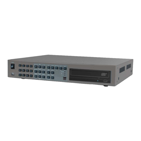
- Page 1 VCE300 S ERIES MPEG 4 4/8/16 Channel Network DVR , 120 fps Models VCE304, VCE308, VCE316 DIGIMERGE TECHNOLOGIES INC.
- Page 2 PRECAUTION This symbol is intended to alert the user to the presence of unprotected “Dangerous voltage" within the product's enclosure that may be strong enough to cause a risk of electric shock. This symbol is intended to alert the user to the presence of important operating and maintenance (servicing) instructions in the literature accompanying the appliance.
- Page 3 CONTENTS All the safety and operating instructions must be read before the unit is operated. • Make sure to switch the power off before you install the DVR. • There is the danger of an electric shock if the DVR is opened by an unqualified service engineer or installer.
-
Page 4: Table Of Contents
CONTENTS TABLE OF CONTENTS 1. FEATURE LIST ---------------------------------------------------------------------------------- 2. PACKING DETAIL ------------------------------------------------------------------------------------------ 3. LOCATION AND CONTROL ----------------------------------------------------------------- 3.1 FRONT PANEL CONTROLS ------------------------------------------------------------------------------- 3.2 REAR PANEL CONNECTORS ----------------------------------------------------------------------------- 4. INSTALLATION --------------------------------------------------------------------------------------------- 4.1 TOTAL CONNECTION LAY-OUT ------------------------------------------------------------------------- 4.2 INDIVIDUAL CONNECTION -------------------------------------------------------------------------------- 4.2.1 CAMERA ------------------------------------------------------------------------------------------ 4.2.2 AUDIO --------------------------------------------------------------------------------------------- 4.2.3 MONITOR ----------------------------------------------------------------------------------------------- 4.2.4 EXTERNAL HDD BAY --------------------------------------------------------------------------... - Page 5 CONTENTS 6.3 RECORD --------------------------------------------------------------------------------------------------------- 6.3.1 RECORD SETUP ----------------------------------------------------------------------------------- 6.3.2 RECORD PROGRAM ----------------------------------------------------------------------------- 6.3.3 IMAGE QUALITY -------------------------------------------------------------------------------------- 6.3.4 AUDIO RECORD ------------------------------------------------------------------------------------- 6.3.5 OVERWRITE ----------------------------------------------------------------------------------------- 6.3.6 PLAY MODE ----------------------------------------------------------------------------------------- 6.3.7 BACKUP MODE -------------------------------------------------------------------------------------- 6.3.8 HOLIDAY ------------------------------------------------------------------------------------------------- 6.4 EVENT ------------------------------------------------------------------------------------------------------------ 6.4.1 MOTION DETECTION ----------------------------------------------------------------------------- 6.4.2 EVENT SCREEN MODE ------------------------------------------------------------------------- 6.4.3 EVENT RECORD -------------------------------------------------------------------------------------- 6.4.4 EVENT MESSAGE ---------------------------------------------------------------------------------...
- Page 6 FEATURES 7. EXTERNAL TERMINAL INFORMATION --------------------------------------------------- 7.1~2 RS-485 / T.ADJ ----------------------------------------------------------------------------------------- 7.3~4 RELAYOUT / ALARM -------------------------------------------------------------------------------------- 7.5~6 VGA / SERIAL ---------------------------------------------------------------------------------------------- 7.7~8 ETHERNET/USB --------------------------------------------------------------------------------------- 8. SPECIFICATIONS ---------------------------------------------------------------------------- 9. 256 CAMERA INTEGRATION SYSTEM -------------------------------------------------- 10. HDD INSTALLATION ------------------------------------------------------------------------ 10.1 INTERNAL HDD INSTALLATION ------------------------------------------------------------------- 10.2 DVD±RW(or CD-RW) installation------------------------------------------------------------------- 11.
-
Page 7: Feature List
FEATURES Features Chapter 1 Operation Playback, recording, backup and transmission simultaneously Real time single or multi-screen display Pan & Tilt, 2X digital zoom and PIP display Easy operation by IR remote controller, external keypad controller and USB 2.0 Mouse Hidden camera option (covert) User-friendly setup menu and operation Playback Multi-screen playback (Full/4/6/7/9/10/13/16 split) -
Page 8: External Storage
PACKING DETAIL External storage Automatic backup to selected backup HDD (Event backup/ Mirroring) Own external storage device to extend the HDD capacity You can install 10 HDDs in 1 external HDD Bay and connect up to 4 Bay with this DVR. (250GB X 40HDDs = 10TB, 500GB X 40HDD = 20TB, 1TB X 40HDD = 40TB) Audio 4 channels audio recording in real time... -
Page 9: Packing Detail
FEATURES Packing Detail Chapter 2 1. DVR 4. Remote controller 2. Network Viewer Program CD 3. User’s Manual 5. R-HDD Rack Key 6 Rack Mounts 7. AC Adaptor & Power Cord 8. Batteries 9. HDD Screws CONTENTS 1. DVR 2. Network Viewer Program CD 3. -
Page 10: Location And Control
LOCATION AND CONTROL Location and Control Chapter 3 3.1 FRONT PANEL CONTROLS ○ ○ ○ ○ ○ ○ ○ ○ ○ Name Description USB 2.0 port to use a USB memory stick, Mouse or USB external devices Buttons to select the camera or input the password CHANNEL SELECT Audio select button / Button to select the camera or input the password AUDIO SEL / 0... -
Page 11: Rear Panel Connectors
LOCATION AND CONTROL 3.2 REAR PANEL CONNECTORS ○ ○ ○ ○ ○ ○ ○ ○ ○ ○ ○ ○ ○ ○ ○ ○ ○ ○ ○ Name Description ○ BNC input ports for cameras CAMERA IN ○ BNC output(looping) ports for cameras CAMERA OUT ○... -
Page 12: Installation
INSTALLATION Installation Chapter 4 4.1 TOTAL CONNECTION LAY-OUT USER’S MANUAL... -
Page 13: Individual Connection
INSTALLATION 4.2 INDIVIDUAL CONNECTION 4.2.1 Camera • Connect a female BNC connector of each camera to a male BNC connector, “CAMERA IN” port. • Connect the looping BNC output to other inputs as required 4.2.2 Audio (*Refer to the specification) Audio Input •... -
Page 14: Monitor
INSTALLATION 4.2.3 Monitor • Connect the female BNC for monitor output. • Connect the male Y/C cable socket for S-VIDEO monitor output. USER’S MANUAL... -
Page 15: External Hdd Bay
INSTALLATION 4.2.4 External HDD Bay (USB output) INSTALLATION PROCESS. 1) Turn off the power of DVR. 2) Connect the grounding conductor between DVR and external HDD bay. 3) Connect the USB cable between DVR and external HDD bay. 4) Connect the power cords of DVR and each external HDD bay. 5) Plug the power cords of DVR and each external HDD bay. -
Page 16: Usb 2.0 Ports
OPERATION 4.2.5 USB 2.0 ports ○ Three USB ports are provided to connect a USB memory stick, One USB port is on the front panel and the other two are on the rear panel. ○ A USB mouse can be connected to one of the ports. You can use the mouse to navigate through the screens and menus much like you would on a computer. -
Page 17: Operation
OPERATION Operation Chapter 5 5.1 FACTORY DEFAULT * 16CH DVR MENU Setup> QUICK SETUP> QUICK SETUP…………………….….…….…..…...OFF IMAGE SIZE……………………….………………..720x240 RECORD FRAME……………………….……….…..60 EVENT……….…………………………...…………...ALL PRE RECORD TIME……….…………...….………..5SEC POST RECORD TIME………………….…...……..10SEC IMAGE QUALITY…..…………………………………HIGH AUDIO RECORD…………………………….……….OFF REMOTE CONTROL ID…………….…..……….…..ALL SCREEN> AUTO SEQUENCE QUAD-A~E/ SIX/ SEVEN/ NINE-A~B/ TEN/ THIRTEEN/ SIXTEEN….3SEC ADD AUTO SINGLE….………………..…...OFF AUTO-SINGLE CH1~16………………..…..3SEC... - Page 18 OPERATION RECORD> RECORD SETUP RECORD PROGRAM..……………………..6 RECORD PROGRAM (Refer to 6.3.2) IMAGE QUALITY RECORD QUALITY………………………..HIGH AUDIO RECORD AUDIO 1~4………………..…………………..OFF OVERWRITE OVERWRITE……..………………………..…..ON DISK FULL WARNING……..……………….…..5% PLAY MODE.…………………………………….…..FRAME BACKUP MODE..……………………………….…..OFF HOLIDAY HOLIDAY RECORD………………………….….OFF HOLIDAY SETUP(MM/DD) ………………..…..00/00 EVENT> MOTION DETECTION CHANNEL…………………………………...…...1 SENSITIVITY…………………………...….…….3 EVENT SCREEN MODE…………………...…….….…UNCHANGED EVENT RECORD.………………………….…..…..……OFF EVENT MESSAGE..…………………………….……..OFF EVENT MESSAGE RESET……………….……..…..5SEC...
- Page 19 OPERATION COPY……………….………….……..……OFF LIVE AUDIO………………….……………OFF DVR SETUP………………….……………OFF DVR STATUS………………….……….…OFF PTZ CONTROL……………….…………..OFF DVR MENU SETUP FACTORY DEFAULT…………..………...NO LOAD MENU FROM FILE SAVE MENU TO FILE FIRMWARE UPGRADE………………….……….……….NO LINK> NETWORK DHCP……..………………………………….………OFF IP ADDRESS………………………………………..192 168 000 002 SUBNET MASK……………………………………..255 255 255 000 GATEWAY…………………………………………..192 168 000 001 DNS…………………………………………………..000 000 000 000 PORT……………………………………….………..5400 RS232C...
-
Page 20: Button Controls
OPERATION 5.2 BUTTON CONTROLS 5.2.1 POWER ON /OFF After the connection of power cord and other devices with this DVR, turn the power on. The video signal system (NTSC or PAL) is set to NTSC. Power Failure Recovery This DVR automatically reverts back to programmed record parameters upon power restoration. -
Page 21: Multi Screen Mode
OPERATION 5.2.2.2 Auto Sequence Display <ADD AUTO SINGLE : ON> • Press the AUTO button, each screen display will be automatically switching according to the AUTO SEQUENCE setup. • If you set up “ADD AUTO SINGLE : OFF” in the AUTO SEQUENCE setup menu, the single display will be skipped. -
Page 22: Record
OPERATION 5.2.3 RECORD Press the REC button and the following message will be displayed as below; MANUAL MODE Press the REC button to begin recording. To stop recording, press the REC button again. The screen will be turned into real time display mode. -
Page 23: Search & Playback
OPERATION 5.2.4 SEARCH & PLAYBACK Press the SEARCH button, the SEARCH menu screen appears. TIME SEARCH If you press the PLAY button in the real time screen mode, playback will be executed from the end of the previous time search and press the desired channel select button. To exit the playback mode and see the live screen again, press LV/PB button. - Page 24 OPERATION 5.2.4.2 SEARCH & COPY At the SEARCH menu; Move the cursor to TIME SEARCH using button. Press the ENTER button and TIME SEARCH screen appears. Select the desired HDD ID using the (-) or (+) button. Move the cursor to CHANNEL using the button and select the desired channel using the (-) or (+) button.
- Page 25 OPERATION 5.2.4.4 EVENT SEARCH At the SEARCH menu; Move the cursor to EVENT SEARCH using button. Press the ENTER button and the EVENT SEARCH menu screen appears. Select the desired HDD ID using the (-) or (+) button. Move the cursor to CHANNEL using the button and select the desired channel using the (-) or (+) button.
- Page 26 OPERATION Select the desired HDD ID using the (-) or (+) button. Move the cursor to the desired position of SEARCH TIME using the buttons, and then set up the desired time using the(-), (+) buttons. Press the ENTER, and the list searched appears. When the list appears on the screen, select the desired list using buttons and press the ENTER button for the playback.
- Page 27 OPERATION When the list appears on the screen, select the desired list using buttons. Press the ENTER button for the playback. <How to make Bookmark list> Press the “PB/PAUSE” button to playback. Find the desired image using the SLOW, FAST, DIR buttons.
-
Page 28: Play Button Information
OPERATION 5.2.5 PLAY BUTTON INFORMATION 5.2.5.1 SLOW ( Press this button to make the speed level which is slower than normal speed (X1) and displayed it at the upper left side of screen as below;(If you press this button again, the playback speed will be changed in the order of the below seven speed level) ½... -
Page 29: Digital Zoom
OPERATION 5.2.6 DIGITAL ZOOM Press the desired camera number button you wish to display on the monitor. Press the D-ZOOM button. The indication screen appears on the main screen. Press the buttons to select the desired location. Press the ESC button to exit this screen. 5.2.7 SCREEN SELECT(LV/PB) _8CH During the playback, press the LV/PB button to convert the screen into real time display mode. -
Page 30: Spot Monitor
OPERATION 5.2.8 SPOT MONITOR Spot Monitor Set up the desired mode in “SPOT” of “SCREEN MENU” before executing the SPOT mode. This function allows you to select any LIVE camera to the SPOT monitor while you are on PLAYBACK MODE. This is helpful in cases you need to have an important LIVE camera all the time 5.2.8.1 MANUAL MODE Press the “SPOT”... -
Page 31: Copy
OPERATION 5.2.9 COPY Press the COPY button to copy the recorded images into other media and the COPY MENU screen appears. 5.2.9.1 COPY 5.2.9.1-1 COPY TO EXTERNAL HDD At the COPY menu, Move the cursor to COPY using the buttons. Press the ENTER button and the following screen appears. -
Page 32: Dvr Status
OPERATION 5.2.9.1-2 COPY TO USB memory stick At the COPY menu, Move the cursor to COPY using the buttons. Press the ENTER button and the following screen appears. Select the desired MEDIA using (-), (+) buttons. Move the cursor to HDD ID using the buttons and select the desired HDD to copy among HDD IDs using the (-), (+) buttons. -
Page 33: Ptz Control
OPERATION 5.2.9.1-3 COPY TO CD-R/ CD-RW/ DVD±RW/ DVD-RAM At the COPY menu, Move the cursor to COPY using the buttons. Press the ENTER button and the following screen appears. Select the desired MEDIA(INTERNAL CD-RW/DVD) (-), (+) buttons. Move the cursor to HDD ID using the buttons and select the desired HDD to copy among HDD IDs using the (-), (+) buttons. -
Page 34: Function Button
OPERATION Move the cursor using the buttons and select “YES” or “NO” and then press the ENTER button. 5.2.10.1-5 CONTINUE COPY If the media is full during copying, you can see the following message, “USB MEDIA FULL OR FAIL PRESS [COPY]” message. Press the COPY button and the following screen appears. - Page 35 OPERATION 5.2.10.3 MEDIA FORMAT At the COPY menu, Move the cursor to MEDIA FORMAT using the buttons. Press the ENTER button and the following screen appears. Select formatting media using the (-), (+) button. Move the cursor to MEDIA FORMAT and then press the “ENTER” button. The message, “FORMATTING”...
- Page 36 OPERATION 5.2.11 PTZ CONTROL 5.2.11.1 PTZ control in live view Press the “PTZ” button to control pan, tilt and zoom functions of PTZ camera and the PTZ channel, model name and ID will be displayed on the left side of the monitor as the following picture.
-
Page 37: Audio Select
OPERATION 5.2.12 FUNCTION BUTTON You need this button to control “USER” mode of RELAY 4 SELECT. Please refer to 6.4.8 RELAY OUTPUT. 5.2.13 AUDIO SELECT < Audio select > You can select audio channels regardless of monitoring screen. Press the “0(audio select)” button and then press the desired number button and you can hear audio of selected channel regardless of monitoring screen. -
Page 38: Remote Controller
OPERATION 5.3 REMOTE CONTROLLER Button Name Description ○ ○ REMOTE Refer to 6.5.6 REMOTE CONTROLLER ID CONTROLLER ID in the system setup ○ (IRIS-/+) Iris close and open of PTZ ○ (ZOOM-/+) Zoom in and out of PTZ Enter the spot mode / Return to the ○... -
Page 39: Menu Setup
MENU SETUP MENU setup Chapter 6 ENTRANCE OF THE MENU SETUP Press the MENU button for the desired DVR setting. You can use the mouse instead of buttons on the front panel of DVR. Simply click the desired icon or item in case of using the mouse. 6.1 QUICK SETUP Press the MENU button and the QUICK SETUP menu appears as the following picture. -
Page 40: Pre Record Time
MENU SETUP alarm, loss, motion). NOTE: Divide event type into three classes( 6.1.5 PRE RECORD TIME Select the desired time for pre-recording using the (-), (+) buttons. When video loss, alarm or motion is detected, the DVR will store pre-recorded data during the selected time. -
Page 41: Screen
MENU SETUP 6.2 SCREEN To set up the SCREEN menu, Move the cursor to the SCREEN icon using the buttons in the MENU screen. Press the ENTER button when the cursor is on the SCREEN icon and the following items appear. 6.2.1 AUTO SEQUENCE At the SCREEN menu, Move the cursor to the AUTO SEQUENCE using... -
Page 42: Add Auto Single
MENU SETUP [ 16CH DVR ] Move the cursor to each single or split channel using the buttons. When the desired channel is selected, change the value of AUTO SEQUENCE duration using the (-), (+) buttons to set the length of time for switching each channel in sequence. •... -
Page 43: Display
MENU SETUP 6.2.2 DISPLAY At the SCREEN menu, Move the cursor to the DISPLAY using buttons. Press the ENTER button when the cursor is on the DISPLAY and the following items appear. To exit this DISPLAY menu, press the ESC button. 6.2.2.1 HDD FREE SPACE At the DISPLAY menu, Move the cursor using the... -
Page 44: Date&Time Mode
MENU SETUP 6.2.2.5 DATE&TIME MODE At the DISPLAY menu, Move the cursor using the buttons to select the DATE&TIME MODE. Use the (-), (+) buttons to choose “MM/DD/YY”, “DD/MM/YY” or “YY/MM/DD”. • The default is “MM/DD/YY”. YY/MM/DD : All date and time will be displayed in numbers. Ex. -
Page 45: Title
MENU SETUP 6.2.3 TITLE At the SCREEN menu, Move the cursor to the TITLE using buttons. Press the ENTER button when the cursor is on the TITLE and the following 2 pages screen appears. Use the buttons to see the next page. Press the ENTER button after selecting desired channel using the buttons and the following screen appears. -
Page 46: Multi Screen
MENU SETUP 6.2.4 MULTI SCREEN You can select the desired channels and make a 4 split screen and a 9 split screen using this menu. At the SCREEN menu, Move the cursor to the MULTI SCREEN using buttons. Press the ENTER button when the cursor is on the MULTI SCREEN and the following screen appears. -
Page 47: Covert
MENU SETUP 6.2.5 COVERT At the SCREEN menu, Move the cursor to the COVERT using the buttons. Press the ENTER button when the cursor is on the COVERT and the following 2 pages screen appears. Move the cursor and select the desired item using the buttons. -
Page 48: Spot
MENU SETUP 6.2.6 SPOT At the SCREEN menu, Move the cursor to the SPOT using buttons. Press the ENTER button when the cursor is on the SPOT and the following screen appears. To exit this SPOT menu, press the ESC button. 6.2.6.1 SPOT MODE Use the (-), (+) buttons to select the SPOT MODE. -
Page 49: Record
MENU SETUP 6.3 RECORD To set up the RECORD menu, Move the cursor to the RECORD icon using the in the MENU screen. Press the ENTER button when the cursor is on the RECORD icon and the following items appear. 6.3.1 RECORD SETUP ( SCHEDULE RECORDING) This menu allows you to configure a weekly recording schedule. -
Page 50: Record Program
MENU SETUP 6.3.2 RECORD PROGRAM This feature uses predefined recording modes to create new ones according with your own needs. This means you can create different programs using existing predefined programs. You have available up to 10 different programs ( 0-9). These programs will be used to setup the recording schedule on the RECORD SETUP menu. - Page 51 MENU SETUP Recording IPS Table <WHAT DOES THE EACH ITEM MEANS?> 1. REC PROGRAM Shows the current PROGRAM #. Example PROGRAM0. Select the program according with your needs .Predefine programs are from 0 – 9. • User can choose the program number to be modified here. 2.
- Page 52 MENU SETUP There are two types of events: SINGLE and COMPLEX. EVENT CH ONLY ALL CHANNELS SINGLE Under the EVENT IPS the DVR will Under the EVENT IPS the DVR will record the channel triggered by any record the channels triggered by any event using the higher IPS on a event with the IPS value predefined or particular channel.
- Page 53 MENU SETUP exceed the maximum IPS of a group. And the total EVENT IPS is always the maximum IPS of a group because the remains of the EVNET IPS for a channel will be allocated to other channels evenly according to the automatic calculated value. So when event(s) happen while the normal record is on, the maximum IPS of a group will be used.
- Page 54 MENU SETUP 10 PREDEFINED PROGRAMS ARE INCLUDED BY DEFAULT. PROGRAMS ARE AVAILABLE FROM 0 - 9. PROGRAM 0. PROGRAM 1 FEATURES. FEATURES RECORDING MODES: RECORDING MODES: NORMAL (Continuous) : 1 ips NORMAL (Continuous) : 4 fps EVENT EVENT COMPLEX/EVENT CH ONLY 1 SINGLE / EVENT CH ONLY 15 fps RESOLUTION .
- Page 55 MENU SETUP PROGRAM 4. PROGRAM 5 FEATURES. FEATURES. RECORDING MODES: RECORDING MODES: NORMAL (Continuous) : 2 ips NORMAL (Continuous) : 1 ips EVENT EVENT SINGLE /EVENT CH ONLY 15 SINGLE /EVENT CH ONLY 30 RESOLUTION . 720 X 240 RESOLUTION . 720 X 240 QUALITY: N/N QUALITY: H/H PRE/POST 5/10...
- Page 56 MENU SETUP PROGRAM 8. PROGRAM 9 FEATURES. FEATURES. RECORDING MODES: RECORDING MODES: NORMAL (Continuous) : 1 ips NORMAL (Continuous) : 1 ips EVENT EVENT COMPLEX /EVENT CH ONLY 1 i SINGLE /EVENT CH ONLY 10 i RESOLUTION . 720 X 480 RESOLUTION .
- Page 57 MENU SETUP PROGRAM EXAMPLES. Based on the most common applications you can use an existing program as a reference ( # 3 ) to create a new configuration based on you own needs. Once you finish your program make sure to add it to the SCHEDULE PROGRAM and SAVE it.
-
Page 58: Image Quality
MENU SETUP 6.3.3 IMAGE QUALITY At the RECORD menu, Move the cursor to the IMAGE QUALITY using buttons. Press the ENTER button when the cursor is on the IMAGE QUALITY and the following screen appears. Select the desired RECORD QUALITY using the (-), (+) buttons. And you can see the size of each image quality and how long you can record in the installed HDDs by the image quality. -
Page 59: Overwrite
MENU SETUP 6.3.5 OVERWRITE This feature allows you to enable or disable the hard drive overwrite feature. At the RECORD menu, Move the cursor to the OVERWRITE using buttons. Press the ENTER button when the cursor is on the OVERWRITE and the following screen appears. -
Page 60: Play Mode
MENU SETUP 6.3.8 HOLIDAY At the RECORD menu, Move the cursor to the “HOLIDAY” using buttons. Press the “ENTER” button to set up “HOLIDAY” and the HOLIDAY menu screen appears. Set up “ON” or “OFF” of HOLIDAY RECORD using the (-), (+) buttons. Move the cursor using buttons and set up the value using the (-), (+) buttons. -
Page 61: Motion Detection
MENU SETUP 6.4.1 MOTION DETECTION At the EVENT menu, Move the cursor to the MOTION DETECTION using buttons. Press the ENTER button when the cursor is on the MOTION DETECTION and the following screen appears. 6.4.1.1 CHANNEL At the MOTION DETECTION menu, Move the cursor to CHANNEL using buttons. -
Page 62: Event Screen Mode
MENU SETUP 6.4.2 EVENT SCREEN MODE At the EVENT menu, Move the cursor to the EVENT SCREEN MODE using buttons. Select the EVENT SCREEN MODE using the (-), (+) buttons. UNCHANGED : Keeping the current screen even if the event occurs. FULL SCREEN : Display the full screen of the channel which the event occurs. -
Page 63: Sensor Input
MENU SETUP 6.4.7 SENSOR INPUT At the EVENT menu, Move the cursor to the SENSOR INPUT using the buttons. Press the ENTER button when the cursor is on the SENSOR INPUT and the following 2 pages screen appears. Select the desired channel using the buttons. -
Page 64: Relay Output
MENU SETUP 6.4.8 RELAY OUTPUT At the EVENT menu, Move the cursor to the “RELAY OUTPUT” using the buttons. Press the ENTER button when the cursor is on the “RELAY OUTPUT” and the following screen appears. Move the cursor using the buttons and set up the value using the (-), (+) buttons. -
Page 65: System
MENU SETUP 6.5 SYSTEM To set up the SYSTEM menu, Move the cursor to the SYSTEM icon using the in the MENU screen. Press the ENTER button when the cursor is on the SYSTEM icon and the following items appear. 6.5.1 HDD At the SYSTEM menu, Move the cursor to the HDD using the... -
Page 66: Hdd Configuration
MENU SETUP 6.5.1.1 HDD CONFIGURATION At the HDD menu, Move the cursor to HDD CONFIGURATION using the buttons. Press the ENTER button when the cursor is on the HDD CONFIGURATION and the following screen appears. Use the buttons to move the cursor and use the (-), (+) buttons to change the value. -
Page 67: Clock
MENU SETUP 6.5.1.3 BACKUP HDD FORMAT At the HDD menu, Move the cursor to “BACKUP HDD INITIALIZE” using the buttons. Press the “ENTER” button when the cursor is on the “BACKUP HDD FORMAT” and the following screen appears. If you want to initialize, move the cursor to “YES” and then press the ENTER button. If not, move the cursor to “NO”... -
Page 68: Video Standard
MENU SETUP 6.5.2.2 TIME ADJUST At the CLOCK menu, Move the cursor to the TIME ADJUST using the buttons. Press the ENTER button when the cursor is on the TIME ADJUST and the following screen appears. Select “ON” or “OFF” using the (-), (+) buttons when the cursor is on “INTERNET TIME ADJUST”. -
Page 69: Remote Control Id
MENU SETUP 6.5.5 REMOTE CONTROL ID At the SYSTEM menu, Move the cursor to the REMOTE CONTROL ID using the buttons. Set the REMOTE CONTROL ID using the (-), (+) buttons. If you are operating more than one DVR in the same place and wish to use the remote controller, the remote controller ID setup is required. -
Page 70: Password Check
MENU SETUP 6.5.7.1 PASSWORD CHECK At the ADVANCED SETUP menu, Move the cursor to the PASSWORD CHECK using the buttons. Select ON or OFF using the (-), (+) buttons. If you select OFF, password menu won’t work. 6.5.7.2 SET PASSWORD At the ADVANCED SETUP menu, Move the cursor to the SET PASSWORD using the buttons. -
Page 71: Dvr Menu Set
MENU SETUP 6.5.7.3 USER AUTHORITY At the ADVANCED SETUP menu, Move the cursor to the USER AUTHORITY using the buttons. Press the ENTER button when the cursor is on the USER AUTHORITY and the following screen appears. Move the cursor using the buttons and change the value using the (-), (+) buttons. -
Page 72: Firmware Upgrade
MENU SETUP 6.5.7.4.2 LOAD MENU FROM FILE At the DVR MENU SETUP menu, Insert the USB memory stick to download the menu file from the USB memory stick. Move the cursor to the LOAD MENU FROM FILE using the buttons and then press the ENTER button. -
Page 73: Link
MENU SETUP 6.6 LINK To set up the LINK menu, Move the cursor to the LINK icon using the in the MENU screen. Press the ENTER button when the cursor is on the LINK icon and the following items appear. 6.6.1 NETWORK At the LINK menu, Move the cursor to the NETWORK using the... -
Page 74: Dhcp
MENU SETUP <Fixed IP> 6.6.1.1 DHCP At the NETWORK menu, Move the cursor to the DHCP using the buttons. Select “OFF” using the (-), (+) buttons. 6.6.1.2 IP ADDRESS At the NETWORK menu, Move the cursor to the IP ADDRESS using the buttons. -
Page 75: Dynamic Dns
MENU SETUP 6.6.1.7 DYNAMIC DNS At the NETWORK menu, Move the cursor to the DHCP using the buttons. Select “ON” using the (-), (+) buttons. Move the cursor to the DYNAMIC DNS using the buttons. Input the dynamic DNS using the (-), (+) buttons to change the value and buttons to move the cursor. -
Page 76: Rs232C
MENU SETUP 6.6.2 RS232C At the LINK menu, Move the cursor to the RS232C using the buttons. Press the ENTER button when the cursor is on the RS232C and the following screen appears. Use the buttons to choose the item and use the (-), (+) buttons to set the data value. To exit this RS232C menu, press the ESC button. -
Page 77: Ptz
MENU SETUP 6.6.4 PTZ At the LINK menu, Move the cursor to the PTZ using buttons. Press the ENTER button when the cursor is on the PTZ and the following 1 or 2 pages screen appears. Select the desired channel using buttons. -
Page 78: Send E-Mail
MENU SETUP 6.6.5.1 SEND E-MAIL At the E-MAIL menu, Move the cursor to the SEND E-MAIL using the buttons and select “ON” using the (-), (+) buttons to send e-mails when an event happened. 6.6.5.2 SMTP SERVER At the E-MAIL menu, Move the cursor to the SMTP SERVER using the buttons to input the e-mail sever address to be used by DVR. - Page 79 MENU SETUP 6.6.5.4 USER ID At the E-MAIL menu, Move the cursor to the USER ID using the buttons to input the e-mail account to be used by DVR. Press the ENTER button and the following screen appears. Select the character using the buttons and then press the ENTER button.
-
Page 80: Dynamic Dns
MENU SETUP 6.6.6 DYNAMIC DNS At the LINK menu, Move the cursor to the DYNAMIC DNS using buttons. Press the ENTER button when the cursor is on the DYNAMIC DNS and the following screen appears. 6.6.6.1 SERVICE PROVIDER At the DYNAMIC DNS menu, Move the cursor to the SERVICE PROVIDER using the buttons and select “ON”... - Page 81 MENU SETUP 6.6.6.3 USER NAME At the DYNAMIC DNS menu, Move the cursor to the USER NAME using the buttons to input the user name to be used. Press the ENTER button and the following screen appears. Select the character using the buttons and then press the ENTER button.
-
Page 82: Search
MENU SETUP 6.7 SEARCH To set up the SEARCH menu, Move the cursor to the SEARCH icon using the in the MENU screen. Press the ENTER button when the cursor is on the SEARCH icon and the following items appear. ** Please, refer to Search &... -
Page 83: Exit
MENU SETUP 6.9 EXIT At the MENU screen, Move the cursor to the EXIT icon using the buttons. Press the ENTER button when the cursor is on the EXIT icon and the following items appear. Move the cursor to the desired item using the buttons and press the ENTER button. -
Page 84: External Terminal Information
EXTERNAL TERMINAL INFORMATION External Terminal Information Chapter 7 7.1 RS-485 These ports are to control the connected PTZ cameras and can be used to connect the external controller. DESCRIPTION TA(TX+) RS485:Transmit data TB(TX-) RS485: Receive data 7.2 T.ADJ Time adjust input port is high level at normal and check signal every 100ms. -
Page 85: Relayout / Alarm
EXTERNAL TERMINAL INFORMATION 7.3 RELAY OUT For controlling alarm output by relay DESCRIPTION DESCRIPTION NO(Normal Open) NO(Normal Open) ALARM CM(Common) CM(Common) POWER NO(Normal Open) NO(Normal Open) USER V-LOSS NOT USED CM(Common) CM(Common) HDD ERROR 7.4 ALARM DESCRIPTION EXTERNAL ALARM 1 INPUT EXTERNAL ALARM 2 INPUT EXTERNAL ALARM 3 INPUT EXTERNAL ALARM 4 INPUT... -
Page 86: Vga / Serial
EXTERNAL TERMINAL INFORMATION 7.5 VGA This DVR is compatible with TFT LCD monitor in PAL mode. This DVR supports 1024 x 768 resolution & 70Hz refreshed rate in NTSC/PAL mode. DESCRIPTION RED(Red Video [75ohm, 0.7Vp-p] ) GREEN(Green Video [75ohm, 0.7Vp-p] ) BLUE(Blue Video [75ohm, 0.7Vp-p] ) 4~12 Reserved... -
Page 87: Ethernet/Usb
EXTERNAL TERMINAL INFORMATION 7.7 Ethernet / USB For both 10Base-T and 100 Base-TX. DESCRIPTION N/C (Not Connected) N/C (Not Connected) RX-(Receive Data-) N/C (Not Connected) N/C (Not Connected) RX+(Receive Data+) TX-(Transmit Data-) TX+(Transmit Data+) ETHERNET DESCRIPTION USB2 USB DATA - USB1 USB DATA + DIGITAL VIDEO RECORDER... -
Page 88: Specifications
SPECIFICATIONS Specifications Chapter 8 1. VIDEO Input Level 1.0 Vp-p±10% Composite, 75Ω Balanced Video Standard NTSC(525 lines)/ PAL(625 lines)/ AUTO NTSC 120fps Display Speed 100fps NTSC 720(H) X 480(V) Display Resolution 720(H) X 576(V) Main 1.0Vp-p Composite, 75Ω Balanced (YC Output) Spot 1.0Vp-p Composite, 75Ω... - Page 89 SPECIFICATIONS External control (RS-232C) / Serial For debugging : 9 pins male DSUB Terminal Block External control (RS-485) Alarm Input 16CH 4 Relay output : 3 pins terminal block Alarm Output (Normal-Open, Normal-Close, Common) x 4 Ethernet RJ45 connector, 10/100 Mbps 7.
- Page 90 SPECIFICATIONS < Recording Speed Table > *Note 1, 2 Unit : ips Model 4CH/ 8CH /16CH Recording Speed NTSC 360 x 240 720 x 240 720 x 480 360 x 288 720 x 288 720 x 576 Compression Method MPEG4 RECORDING CONDITIONS (NTSC) Based on 120GB of storage with the installation of 1 camera.
-
Page 91: Camera Integration System
256 CAMERA INTEGRATION SYSTEM 256 Camera Integration system Chapter 9 Block Diagram DIGITAL VIDEO RECORDER... -
Page 92: Hdd Installation
SPECIFICATIONS HDD Installation Process Chapter 10 10.1 Internal HDD installation 10.1.1 How to install the internal Hard Disk Drive(s). ) Unscrew on the top, the side and the rear of this unit as indicated to remove the cover. Caution) Plug out the power cord before addition / removal / change of HDD 2) Remove the upper cover from the unit and unscrew to remove the rack mounts... - Page 93 HDD INSTALLATION PROCESS 4) Place the HDD(s) on the HDD plate and screw as indicated. Put the ring guides same as picture on the rubber before screwing. (Set the master or slave of HDD before fixing the HDD(s) into DVR. Refer to the HDD Jumper Setting Information.) * All HDDs must be set by slave or master 5) Connect the power and the flat cables...
- Page 94 SPECIFICATIONS 10.1.2 How to install Hard Disk Drive(s) into the removable HDD rack. 1) Grip the strap of removable HDD rack and pull it out. 2) Remove the cover of removable HDD rack and connect the HDD with the cables as indicated.
-
Page 95: Dvd±Rw(Or Cd-Rw) Installation
HDD INSTALLATION PROCESS 10.2 DVD±RW(or CD-RW) installation 1) Put out the cables and unscrew to remove the removable HDD rack as indicated. Note :If you want to install DVD±RW (or CD-RW) into this DVR, you need a USB to IDE interface board. - Page 96 SPECIFICATIONS 6)Screw to fix the DVD±RW(or CD-RW) as indicated. 7) Prepare for the USB to IDE interface board and parts to connect it as the picture. 8) Connect the USB to IDE interface board and cable as the picture and then close the upper cover of the unit.
-
Page 97: Network Client Viewer Manual
DYNAMIC DDNS SERVER SETUP Chapter 11 Network Viewer (DIGI-Client 4.0) 11.1 Installation of Network Viewer Software 11.1.1 System requirement • Pentium III or above recommended • O/S : Microsoft Windows 2000 / XP • 128MB RAM or above recommended • Super VGA 16M or above recommended •... -
Page 98: Add A New Site Information
11.2.1 Add a new site information Click the “Select a DVR” button to display the DVR List on the screen. Fill out Type, DVR Name, IP address and Password to add the desired units into the DVR information box, and then click on the “Add” button to save the information. 11.2.2 Change the site information In case of any changes, type new information into the box after selecting the desired DVR on the... -
Page 99: Dvr Search
DYNAMIC DDNS SERVER SETUP 11.3 DVR search : This menu allows you to detect all the units on the local network. Click “Search DVR” button to display the “Search” menu window. Click the “Search” button, and then all the units on the local network will be detected and listed on the screen. -
Page 100: File Search
11.5 File Search At the above main menu controller, Click the “File Search” button and the “File list” window will appear on the PC screen. If you want to search images saved in CD-RW, DVD±RW or PC, insert the CD or DVD into your PC and click the “File Search”... -
Page 101: Arrange The Screen
DYNAMIC DDNS SERVER SETUP 11.6 Arrange the screen Use this button when you want to arrange the view screens. At the above main menu controller, Click the “Arrange” button when you access more than one DVR and the windows are arranged in a grid on your PC screen. -
Page 102: Option
11.7 Option Insert the CD into the CD-ROM drive, and then please double-click the icon of Network viewer and the following main menu controller will appear on the PC screen. Click the “Option” button to change the other MENU setups. Check the desired Option and then click the OK button. -
Page 103: Control
DYNAMIC DDNS SERVER SETUP 11.8 Control 11.8.1 Screen Display : Images can be viewed in a full or multi format on each screen. a. Full screen display - Click the desired channel button and the full screen of the channel will be displayed. b. -
Page 104: Ptz
11.8.3 PTZ This menu allows you to control the PTZ camera through the network. Click the “PTZ” button to display the following PTZ controller.. Click the button to tilt up or down. Click the button to pan left or right. Click the “ZOOM( or +)”... -
Page 105: Setup
DYNAMIC DDNS SERVER SETUP 11.8.4 SETUP 11.8.5 You can modify DVR MENU setup through the network. Click the “SETUP” button on the control menu bar to display the DVR setup screen after connecting the view screen. (It is possible only for master connection.) Click the “Save to file”... -
Page 106: Print
11.8.6 PRINT 2006/04/24 15:00:54 After connecting the view screen, Click the “PRINT” button on the control menu bar to print the desired image. And the preview window will be displayed as the above picture. Set up the desired option and then click the Print button of the preview window. 11.8.7 COPY After connecting the view screen, Click the “COPY”... -
Page 107: Audio In
DYNAMIC DDNS SERVER SETUP 11.8.8 AUDIO IN After connecting the view screen, Click the “Audio In” button on the control menu bar to input the audio. Sound of your PC will travel into the DVR. 11.8.9 AUDIO OUT After connecting the view screen, Click the “Audio Out”... -
Page 108: Calendar Search
11.8.11 CALENDAR SEARCH After connecting the view screen, Click the “CALENDAR” button on the control menu bar and you can see the Calendar Search window like the following. Select the desired date and then click the Play button to play the images of the selected date. 11.8.12 EVENT SEARCH : You can review the event list that was triggered on the DVR. -
Page 109: Text Search
DYNAMIC DDNS SERVER SETUP 11.8.13 TEXT SEARCH After connecting the view screen, Click the “TEXT” button on the control menu bar and you can see the Text Search window like the following. Select the desired HDD mode and the channel and then set the Search Time. Input the word which you want to search and then click the “Search”... -
Page 110: Log Search
11.8.15 LOG SEARCH : You can search and playback the images by logging. Click the “LOG” button on the control menu bar to display the Log Search window. Set the Search Time, and then click the Search button. Click the “Next” button to search the next list. NOTE: When the DVR is in Setup mode, this search function will not be performed. -
Page 111: Key Information
DYNAMIC DDNS SERVER SETUP 11.9 Key Information 11.9.1 PAUSE Click this button to pause the images during the playback or live. 11.9.2 PLAY (Reverse & Forward) Use these buttons to playback images at normal speed in either direction. 11.9.3 FAST (Reverse & Forward) Use these buttons to playback images faster than normal speed in either direction. -
Page 112: Appendix . Using The Ddns Server For Remote Connection
APPENDIX . USING THE DDNS SERVER FOR REMOTE CONNECTION Registering for the DDNS Service 1. Use a computer to register and make sure to have Internet connection https://ddns.digimerge.net 2. Open a browser window and enter and press ENTER. 3. Select “Create Account” option and fill in the information USER’S MANUAL... - Page 113 DYNAMIC DDNS SERVER SETUP Enter the following information to create a new account: 1. Product Code: i.e VCE300 ( 4ch /8ch/16ch) 2. MAC Address: Enter the DVR/ MAC Address . To find the DVR Mac address press the STATUS button on your DVR. The Mac Address with appear on your screen. Note: Enter the Mac address without spaces.
-
Page 114: Ddns
Once the registration has finished an email will confirm the registration and will provide you a domain name. Dear John, Thank you for activating your free Dynamic DNS account for your Digimerge DVR. Once you have set up your Digimerge device and configured your network, you will be able to view your video images from anywhere in the world using the URL shown at the end of this message. - Page 115 DYNAMIC DDNS SERVER SETUP system. Attempting to use the URL within the first 5 minutes of registration may also prolong the URL update time. When setting up the DIGI client 4.0 applications for remote access use just the domain name in field of “Domain name”...
- Page 116 DOMAIN NAME Enter your domain name from the email received when your registered your DVR. (i.e johndenver) At the DYNAMIC DNS menu, Move the cursor to the DOMAIN NAME using the buttons to input the domain name to be used. Press the ENTER button and the following screen appears.
- Page 117 DYNAMIC DDNS SERVER SETUP PASSWORD Enter your password from the email received when your registered your DVR. (i.e smile) At the DYNAMIC DNS menu, Move the cursor to the PASSWORD using the buttons to input the account password to be used by DVR. Press the ENTER button and the following screen appears.
-
Page 118: Warranty
Limited Warranty Warranty: Subject to the exclusions and limitations below, Digimerge warrants to the initial end-user purchaser that the product will be free from defects in material and workmanship for a period of one year from the date of purchase. For valid warranty claims made during the warranty period, upon proof of purchase, defective products will, at the election of Digimerge, be repaired or replaced without charge.
Need help?
Do you have a question about the VCE304161 and is the answer not in the manual?
Questions and answers