
Related Manuals for Digimerge DHU104 Series


Summary of Contents for Digimerge DHU104 Series
-
Page 1: Instruction Manual
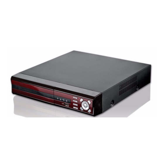
DIGITAL VIDEO SURVEILLANCE RECORDER WITH PENTAPLEX OPERATION AND MPEG4 VIDEO COMPRESSION INSTRUCTION MANUAL English Version 1.0 MODELS: DHU104 SERIES www.digimerge.com © Copyright 2008 Digimerge Technology Inc. - Page 2 CCTV applications. The intuitive graphic user interface and mouse driven navigation make the DHU104 easy to program and easy to use. The unit is also network ready and comes complete with remote video management software and free DDNS support.
-
Page 3: Important Safeguards
Important Safeguards In addition to the careful attention devoted to quality standards in the manufacture process of your video product, safety is a major factor in the design of every instrument. However, safety is your responsibility too. This sheet lists important information that will help to assure your enjoyment and proper use of the video product and accessory equipment. - Page 4 Important Safeguards Service 13. Servicing - Do not attempt to service this video equipment yourself as opening or removing covers may expose you to dangerous voltage or other hazards. Refer all servicing to qualified service personnel. 14. Conditions Requiring Service - Unplug this video product from the wall outlet and refer servicing to qualified service personnel under the following conditions.
-
Page 5: General Precautions
4. Keep enough space around the unit for ventilation. Slots and openings in the storage cabinet should not be blocked 5. During lightning storms, or when the unit is not used for a long time, disconnect the power supply, antenna, and cables to protect the unit from electrical surge www.digimerge.com General Precautions... -
Page 6: Dvr Features
DVR FEATURES DVR FEATURES • 4-channel operation • Pentaplex operation allows you to View, Playback Record simultaneously (Local & Remote) • Advanced MPEG4 video compression • 120 fps recording • Graphical User Interface • USB ports for data back up & firmware upgrades •... -
Page 7: Table Of Contents
Table of Contents Getting Started ... 1 Front Panel ... 2 Rear Panel ... 3 Remote Control ... 4 Mouse Control ... 5 Display Modes ... 6 Initial Loading Sequence ... 6 Individual Camera Display ... 6 Network Connectivity Indicator ... 7 Display Modes ... - Page 8 Appendix 1: System Specifications ... 47 Appendix 1: System Specification (cont’d.) ... 48 Appendix 1: System Specification (cont’d.) ... 49 Appendix 2: Digimerge Client Software Requirements ... 50 Appendix 3: Monitor Out ... 51 Appendix 4: Connecting Motion/Alarm Devices ... 52 Appendix 5: Connecting a PTZ Camera ...
-
Page 9: Getting Started
Getting Started The system comes with the following components: DIGITAL VIDEO SURVEILLANCE RECORDER REMOTE CONTROL HARD DRIVE SIZE, NUMBER OF CHANNELS, AND CAMERA CONFIGURATION MAY VARY BY MODEL. PLEASE REFER TO YOUR PACKAGE FOR SPECIFIC CONTENT DETAILS. CHECK YOUR PACKAGE TO CONFIRM THAT YOU HAVE RECEIVED THE COMPLETE SYSTEM, INCLUDING ALL COMPONENTS SHOWN ABOVE. -
Page 10: Front Panel
Front Panel Front Panel 1. INDICATOR LEDs - Indicates the DVR status: • PWR - Indicates that the DVR is ON/OFF (RED LED). • ALM - Indicates that the unit has an active ALARM. • REC - Indicates that the DVR is currently recording (when the RED LED is ON). •... -
Page 11: Rear Panel
Rear Panel TSC/PAL SWITCH - Set the unit to either NTSC (North America) or PAL (Europe). 1. N 2. BNC VIDEO INPUTS - Channel 1~4 Camera inputs (used to connect Cameras with BNC connection type). Cameras with BNC connections require an additional power adaptor. NOTE: Additional BNC Inputs are available on the 8 and 16 channel models. -
Page 12: Remote Control
Remote Control Remote Control 1. MODE: Press the Mode Button to display the Multi-Function Mode Menu. 2. POWER: Press the Power Button to turn off the Monitor Display. Press to open the Shutdown window. 3. F1: Opens the System Information window. 4. -
Page 13: Mouse Control
Mouse Control Connect a PS/2 mouse to the PS/2 port on the rear panel of the unit. Note: The USB front on the front panel is recommended for media backup. Mouse Controls Use the Left and Right Buttons to open menus and change options: LEFT BUTTON - •... -
Page 14: Display Modes
Display Modes Display Modes Initial Loading Sequence • Press the POWER button located on the front panel of the DVR to start the unit. • The DVR will perform a Hard Drive check • The unit will initially load to a quad split-screen view. -
Page 15: Network Connectivity Indicator
Network Connectivity Indicator The Network Indicators appear when a remote connection is made to the unit via the Remote Agent software, or through the Internet Explorer Web Client: • Green: Indicates that the network connection is stable. • Blue: Indicates that the network connection is experiencing difficulties. -
Page 16: Ptz (Pan/Tilt/Zoom) & Focus Controls
PTZ (Pan/Tilt/Zoom) & Focus Controls PTZ (Pan/Tilt/Zoom) & Focus Controls The PTZ / Focus Menus will only work with PTZ type cameras (not included): PTZ Control Screen Press the PTZ Button on the front panel of the system, or on the Remote Control to access the PTZ Control Screen: •... -
Page 17: System Power Off
System Power Off System Log Off • Open the system Menu and select LOGOFF. • Select LOG OFF and press the ENTER button. • Select Yes and press the ENTER button to log off. • To log on, open the system Menu and select any option and enter your user ID and password in the login window. -
Page 18: Menu Navigation Controls & Tips
Menu Navigation Controls & Tips Menu Navigation Controls & Tips Menu Navigation Controls When navigating the system menu, use the navigation buttons on the remote control to peform the following: 1. Press to select a menu option (selected option will be highlighted in BLUE. 2. -
Page 19: Playback And Navigation Controls
Playback and Navigation Controls 1. Power: Press to turn on the system; press to open the shutdown menu. 2. Display: Press to open the Display menu. 3. Search: Press to open the Search menu. 4. Menu: Press to open the system Menu. 5. -
Page 20: Recording Menu Controls
Recording Menu Controls Recording Menu Controls PANIC RECORDING From the sub-menu, select REC START to begin Panic Recording. To stop panic recording, open the sub-menu and select REC STOP. Record Setup Menu • Right-click anywhere on the screen to open the sub-menu. •... -
Page 21: Simple Recording
SIMPLE RECORDING Simple Recording allows you to easily set recording parameters for each camera using the Time Interval bar. • RECORD QUALITY - Set from Normal, Fine, High, and Highest. • RECORD SIZE - Sets the video capture size for each camera to 352x240, 704x240 or 704x480. -
Page 22: Advanced Recording
Recording Menu Controls ADVANCED RECORDING Under Recording Operations, select Advanced and select APPLY to view the Advanced Recording tab. Use Manual Recording to customize recording size, FPS, image quality, and audio for each camera. You can also set Manual (Panic) Recording Time. Setting Edit parameters for each camera using the Time Interval Bar. -
Page 23: Activation
Activation Select Activation to apply Event Recording (Continuous, Motion, Alarm) to each channel per hour. Note: The changes you make in the SETTINGS menu will be reflected in the ACTIVATION menu. Select the Channel grid and press ENTER. Select individual hour block and press ENTER to open the setup menu. -
Page 24: Manual Recording
Recording Menu Controls MANUAL RECORDING Use Manual Recording to customize recording size, FPS, image quality, and audio for each camera. You can also set Panic Recording Time. Parameters for each camera are set by hour using the Time Interval bar. Press the ENTER key to select the Interval Bar, and navigate using the arrow keys. -
Page 25: Search Mode
Search Mode Search mode allows you to locate previously recorded video by Date and Time, or by Event Type. • Press the Search Button on the front panel or Remote Control, or open the system Menu and select SEARCH. • Enter the User Name and Password (if required). -
Page 26: Search By Event
Search Mode Search By Event Searches the system based on Event Type (Alarm, Motion, Continuous or System). • Press the right arrow button on the front panel or remote control to access the Search By Event screen. • Select From and To dates, Events (Alarm, Continuous, Motion Other) -
Page 27: System Setup Controls
System Setup Controls • Open the MENU screen by pressing the MENU button. Login with your user ID and password if required. • Select SYSTEM SETUP and press the ENTER button. • Scroll through the options by pressing the UP, DOWN buttons on the Front Panel or Remote Control. -
Page 28: System Setup Menu
System Setup Menu System Setup Menu • Open the Menu and select SYSTEM SETUP. • Select DISPLAY and press the ENTER button. The Display Menu controls: OSD - Onscreen display settings control the camera titles, event indicators, and general screen settings. MONITOR - Display settings for Alarm and Events OSD (Onscreen Display) -
Page 29: Monitor
OSD (Onscreen Display) • Motion Sensor Display - Turns the display of the Motion Sensor to: • Active: Display motion sensor of motion detection area. • Inactive: Display motion sensor except motion detection area. • Off: No display of motion sensor. •... -
Page 30: Camera Menu
Camera Menu Camera Menu The Camera Settings and Controls: CAMERA TITLE - Settings for the onscreen display of individual Camera Titles. COLOR SETUP - Color settings for individual cameras. PTZ SETUP - Configuration for PTZ type cameras (not included with the system). MOTION SENSOR - Configuration for Video Motion Detection. -
Page 31: Color Setup
PTZ Setup is for PTZ Type Cameras ONLY, which are not included with this system. For more information on PTZ Cameras, visit us on the web at www.digimerge.com • ADDRESS - Select the physical address location of the PTZ Camera (as connected to the rear PTZ Control Block. -
Page 32: Ptz Properties
Camera Menu PTZ PROPERTIES • Channel No. - Camera Number. • PTZ Driver - The compatible driver selected for the PTZ Camera. • Auto Focus - Sets the Automatic camera focus to ON/OFF. • Auto Iris - Sets the Automatic Shutter to ON/OFF. -
Page 33: Sound Menu
Sound Menu The System Sound settings: AUDIO - Settings for the system Audio for Live and Remote monitoring. BUZZER - Settings for System Buzzer (audible alerts). SOUND • Live Audio - Turns Live System Audio (from the Audio on the terminal) to ON/ OFF. -
Page 34: System Menu
System Menu System Menu The System Setting controls contain: DATE/TIME - Date and Time controls for the system. NETWORK - Network and remote access controls. MAIL - Mail setup USER MANAGEMENT - Controls for system users. SYSTEM MANAGEMENT - System specific settings and controls CONTROL DEVICE - Settings for an external control device (e.g. -
Page 35: Network
• DDNS (Dynamic DNS) - Allows the System to be accessed using a fixed domain (website URL) without entering the IP address. Digimerge offers a free DDNS Service at http:// ddns.digimerge.net • If you use the DDNS, there is no need to enter the IP Address with every connection. -
Page 36: Mail Setup
DHCP is set to ON. Displays the IP address of the local DNS Server (i.e. local Router). • DDNS Server - Set to the free DDNS Server provided by Digimerge (ddns.digimerge.net). • Net Client Port - Default port of 6100. Used for remote connection. -
Page 37: User Management
USER MANAGEMENT • User setup consists of three groups: Administrator, Manager or User. • Up to seven new users can be added to the system. • ADD - Opens the ADD New User screen to configure the new user settings NOTE: A maximum of 4 users can be remotely connected to the System simultaneously. -
Page 38: System Management
System Menu SYSTEM MANAGEMENT • System Information - Navigate to the PRESS button, and choose ENTER to display the System Information. • System Name - Input a name for the system using the Virtual Keyboard. • FW Update - Navigate to the PRESS button, and choose ENTER to update the System Firmware. - Page 39 SYSTEM MANAGEMENT Firmware Update New firmware is periodically available for download from www.digimerge.com. The firmware on the unit can be updated via the USB port: • Download the new firmware from the website. Copy the files from the PC to the USB flash drive.
-
Page 40: Control Device
System Menu SYSTEM MANAGEMENT Factory Defaults The System can be returned to the Factory default settings: • Select the ‘Factory Defaults’ option by selecting the PRESS button. • Login with your user ID and password. • Choose OK to reset the unit, or CANCEL to exit without resetting. -
Page 41: Event / Sensor
Event / Sensor The Event Sensor Setting controls contain: HDD EVENT - Checks the Hard Drive for errors. ALARM INPUT - Configuration settings for an external Alarm sensor (i.e. Door / Window Sensors). ALARM OUTPUT - Sends a signal to an external device when an alarm is detected. -
Page 42: Alarm Input
Event / Sensor ALARM INPUT Configurations for any external alarm device (i.e. a Door or Window Sensor). Refer to the appendices for hardware configuration details. • Operation - Sets the Alarm Sensor Connection Status (Enable / Disable) for an external alarm (i.e. Door or Window Sensors). -
Page 43: Buzzer Output
ALARM OUTPUT • Duration - Sets the Reacted Relay Time. (5sec~5min or Until key-in) • HDD Event - Turns the Alarm ON/OFF when the Hard Drive experiencing problems. • Alarm - Sends the Alarm Out when an Alarm Event is detected (set to ON/ OFF). -
Page 44: Email Notification
Event / Sensor EMAIL NOTIFICATION Note: You must have the option, “Notification,” set to ON in order to configure the options in this menu. • Notification - Sets the E-Mail notification ON/OFF. • HDD Event - A notification is sent if a Hard Drive event is detected (set to ON/ OFF). -
Page 45: Disk Management
Disk Management • Overwrite - Determines how data is maintained when the Hard Drive is full. • ON - When Overwrite is set to ON, data will be overwritten when the Hard Drive is full, starting with the Oldest recording. •... -
Page 46: Archiving
Archiving Archiving The Archive feature copies data from the internal hard drive to backup media such as an external USB hard drive, USB flash drive., or DVD-R/RW drive. • Open the sub-menu and select ARCHIVING. Archiving Menu • From - Select the Start Time and Date for Backup. -
Page 47: Error Messages
Archiving Options Once the Start Time, End Time and Channel Selections have been completed, select the START Button A Drive Usage report will be displayed: • Amount of space (in MB) needed • Start and End Times for Each Channel, with size of recordings (in MB) •... -
Page 48: Network Connectivity Overview
2. Find the IP address of your DVR through the Menu System on the unit. 3. Set up a web account at http://ddns.digimerge.net. 4. Enable PORT FORWARDING on your Router. See “Router Port Forwarding” on page 44. -
Page 49: Ip & Mac Address
IP & MAC Address The IP & MAC Addresses are necessary for DDNS Setup (for remote access to the DVR). To Locate the System information, Press the ENTER button on the Front Panel or Remote Control while viewing the Cameras. The System Info window will be displayed. -
Page 50: Setting Up Your Ddns Account
Network Connectivity Overview Setting Up Your DDNS Account Digimerge offers a free DDNS service for use with your System. A DDNS account allows you to setup a web site address that points back to your Local Network. The following outlines how to set up your free DNS account. - Page 51 ________________________________________________________ * Domain Name: __________________________________________________________ Password: __________________________________________________________ * Only the first part of the Domain Name is required for setup on the System. If the full Domain sent is tomsmith.digimerge.net, the unit requires that only tomsmith be entered. Network Connectivity Overview...
-
Page 52: Router Port Forwarding
Network Connectivity Overview Router Port Forwarding How do I enable Port Forwarding on my Router? You will need to enable port forwarding on your Router to allow for external communications with your DVR for ports: • TCP/IP PORT 6100 • WEB PORT 80 Computers, DVRs, and other devices inside your network can only communicate directly with each other within the internal network. -
Page 53: Ddns Setup
DDNS SETUP Once the DDNS settings have been configured online, the information must be entered on the DVR to allow for remote connection via the Digimerge Client Software (or through Internet Explorer): 1. Open the MENU and select SYSTEM SETUP. -
Page 54: Troubleshooting
When a malfunction occurs, it may not be serious and can be corrected easily. The following describes the most common problems and solutions. Please refer to the following before calling Digimerge Technical Support: Problem: DVR Unit is not receiving power, or is not powering up Check: •... -
Page 55: Appendix 1: System Specifications
Appendix 1: System Specifications General Specifications Video Standard Video Inputs Video Outputs Image Size Operating System Recording Speed Audio Inputs Audio Outputs Audio Compression Standard Video Inputs Hard Disk Secondary Storage Backup File Formats Record Scheduling Playback NTSC / PAL 4 BNC @ 1.0Vp-p, CVBS, 75ohms 1 x Monitor Out 1 x VGA (800x600 @60Hz) -
Page 56: Appendix 1: System Specification (Cont'd.)
Appendix 1: System Specification (cont’d.) Appendix 1: System Specification (cont’d.) Alarm Specifications Alarm Inputs Alarm Outputs Activity Detection Covert Camera Operation PTZ Control Remote Function Recording Specifications Operation Recording Speed Record Scheduling Pre / Post Alarm Event / Log Search Playback Network Specifications Network Interface... -
Page 57: Dvr Specifications
Color Dimensions (WxDxH) Weight As our products are subject to continuous improvement, Digimerge Technology Inc. and its subsidiaries reserve the right to modify product design, specifications and prices, without notice Appendix 1: System Specification (cont’d.) Input: 100 VAC - 240 VAC, 5A, 60/50Hz Output: 12V DC / 5 A Approx. -
Page 58: Appendix 2: Digimerge Client Software Requirements
Hard Drive Recommended System Requirements: Operating System Processor Memory Hard Drive Please refer to the Digimerge Client Software User Guide included with your DVR for further details. Visit the Digimerge support website at compatibility. Windows 2000 Windows XP Home Edition... -
Page 59: Appendix 3: Monitor Out
Appendix 3: Monitor Out Appendix 3: Monitor Out Connect the system to an external monitor or to another DVR or observation system the MONITOR OUT port on the back of the DVR. • MONITOR OUT - Displays exactly what is shown from the DVR (Camera View, Menus, etc.) to a TV or VCR. -
Page 60: Appendix 4: Connecting Motion/Alarm Devices
Appendix 4: Connecting Motion/Alarm Devices Appendix 4: Connecting Motion/Alarm Devices Motion detection and Alarm controls are enabled through the Menu system on the DVR. Additional motion sensor devices can be connected to the system (Motion Sensors, Door/ Window Sensors). A motion detection or sensor unit can be used to send a signal to the DVR to begin camera viewing on the matching Video Channel (when enabled in the Menu): •... -
Page 61: Appendix 5: Connecting A Ptz Camera
System. The PTZ Controls are enabled through the Menu system on the DVR. Additional PTZ Cameras are available at www.digimerge.com Installing a PTZ (RS-445 Type) PTZ Camera: 1. Connect the Transmit Cable to the D+ port on the PTZ Control Block on the DVR. -
Page 62: Appendix 6: Full Connectivity Diagram
Appendix 6: Full Connectivity Diagram Appendix 6: Full Connectivity Diagram The following diagram outlines a general set of connections available with the DVR. (not included) LINE-IN AUDIO / AUDIO OUT (not included) 4 x BNC CAMERAS (not included) ROUTER (not included) (Not Included) PTZ CAMERA MONITOR OUT VGA OUT... -
Page 63: Appendix 7: Replacing The Hard Drive
Appendix 7: Replacing the Hard Drive The system comes with a pre-installed, security-grade 3.5" SATA Hard Drive, however the unit will work with a replacement single SATA Hard Drive (up to 1 TB). NOTE: Make sure that the system is OFF and the power cable has been disconnected before changing the Hard Drive. - Page 64 Appendix 7: Replacing the Hard Drive Formatting the New Hard Drive The new hard drive must be formatted. If a new HARD DRIVE is detected, the system will prompt you to FORMAT the drive. If you do not choose to format the HARD DRIVE, the drive will not be detected by the system.
-
Page 65: Appendix 8: Using The Storage Calculator
Appendix 8: Using the Storage Calculator The Storage Calculator application is used to calculate the amount of recording time available on your Hard Drive, based on the System Recording Settings. This application is located on the Software Installation CD (provided with your System) 1. -
Page 66: Appendix 9: System Setup Tips
Appendix 9: System Setup Tips Appendix 9: System Setup Tips There are several tips outlined below that will assist you in setting up your system: Navigating within the System Menu • Open the MENU screen by pressing the MENU button. Enter the password if required. - Page 67 3. Select the DATE AND TIME Menu. Change the settings by navigating with the UP/ DOWN/LEFT and RIGHT arrow keys. Set the following based on your local Time (and Timezone), and set the current date for the system. • Date/Time - Sets the current system Date and Time.* •...
- Page 68 Appendix 9: System Setup Tips Formatting the Hard Drive Formatting the hard drive after changing the date, and before beginning the recording of YOUR data is recommended, as the system is set to Automatically start recording when powered on (continuous recording setting).
-
Page 69: Camera Setup
Camera Setup Each camera should be assigned a name that corresponds to its use (i.e. Dock1, BackDoor, Cash3, etc.). This name is displayed onscreen, and helps to identify the camera location easily. 1. Enter MENU mode by pressing the MENU button on the front panel of the system (or on the Remote Control). - Page 70 Appendix 9: System Setup Tips Backing up your System Configurations it is recommended to back up your system configurations to a Memory Stick. Configuring your system to meet your specific needs can be time consuming - having a backup of your settings will allow you to reset your unit with your personalized settings in the event of an unwanted change.
-
Page 71: Appendix 10: Using Listen-In Audio
Appendix 10: Using Listen-In Audio How do I enable Listen-In Audio, and how do I set the Listen-in channel? Listen-In Audio is the ability to listen to live audio on ONE channel at a time, between channels 1~4. To listen to live audio on a channel: 1. -
Page 72: Appendix 11: Playing Recorded Video Data
Appendix 11: Playing Recorded Video Data Appendix 11: Playing Recorded Video Data Search mode allows you to locate previously recorded video by Date and Time, or by Event Type. • Press the Search Button on the front panel or Remote Control •... - Page 73 Search By Event Searches the system based on Event Type (Alarm, Motion, Continuous or System). • Press the right arrow button on the front panel or remote control to access the Search By Event screen. • Select From and To dates, Events (Alarm, Continuous, Motion and Other) and Cameras •...
-
Page 74: Appendix 12: Recording Modes
Appendix 12: Recording Modes Appendix 12: Recording Modes The system is set to automatically start recording when powered on. You may wish to change these settings to better suit your security needs. These settings can be changed for an individual camera on one time block, or can be set for multiple cameras for multiple time blocks. - Page 75 Setting Multiple Time Blocks 1. Enter MENU mode by pressing the MENU button on the front panel of the system (or on the Remote Control). Select the RECORD MENU Option. 2. Select the SIMPLE RECORDING MODE menu. Navigate using the up and down arrows on the front panel (or remote control).
-
Page 76: Appendix 13: Setting Up Remote Viewing
4. Enable Port Forwarding on your router. Refer to the included Router Guide and Basics of Remote Video Access Guide for further assistance with your specific network setup and hardware. 5. Setup an account at http://ddns.digimerge.net ROUTER (Not Included) (Not Included) - Page 77 IP & MAC Address The IP & MAC Addresses are necessary for DDNS Setup (for remote access to the DVR). To Locate the System information, Press the ENTER button on the Front Panel or Remote Control while viewing the Cameras. The System Info window will be displayed.
- Page 78 Appendix 13: Setting Up Remote Viewing Setting Up Your DDNS Account Digimerge offers a free DDNS service for use with your System. A DDNS account allows you to setup a web site address that points back to your Local Network. The following outlines how to set up your free DNS account.
- Page 79 __________________________________________________________ Password: __________________________________________________________ * Only the first part of the Domain Name is required for setup on the System. If the full Domain sent is tomsmith.digimerge.net, the unit requires that only tomsmith be entered. Appendix 13: Setting Up Remote Viewing...
-
Page 80: Network - Router Port Forwarding
Appendix 13: Setting Up Remote Viewing Network - Router Port Forwarding You will need to enable port forwarding on your Router to allow for external communications with your DVR for ports: • TCP/IP PORT 6100 • WEB PORT 80 Computers, DVRs, and other devices inside your network can only communicate directly with each other within the internal network. - Page 81 DDNS SETUP Once the DDNS settings have been configured online, the information must be entered on the DVR to allow for remote connection via the Digimerge Client Software (or through Internet Explorer): 1. Open the MENU and select SYSTEM SETUP.
- Page 82 Appendix 13: Setting Up Remote Viewing Digimerge NetViewer Software - Connection Manager The Connection Manager contains the setup information to allow the user to remotely connect to the DVR. Adding a Group Group - Right click on ‘Site’ to add a New Group.
- Page 83 Adding a Site (Individual Unit Configuration) DVR Information - Enter the information specific to the unit: • Name - Enter a name for the unit. • IP / Domain Name - Enter the IP address or Domain Name for the System. This will vary depending on setup (Internal Network Connection or External...
- Page 84 Appendix 13: Setting Up Remote Viewing Digimerge NetViewer Software - Remote Connection Once the site setup profile has been created, a connection can then be made to the DVR: 1. Select the Site profile from the Dropdown List. 2. Press the CONNECT button.
-
Page 85: Limited Warranty
Software & Consumables: All software, accompanying documentation and consumables (including but not limited to fuses and batteries) provided with or as part of the product are furnished AS IS, and are excluded from warranty coverage. Digimerge is not obligated to provide the end-user with a substitute product during the warranty period or at any time. - Page 86 No claims or statements regarding the product, whether written or verbal, by salespeople, retailers, dealers or distributors, that are not contained in this limited warranty or in the owner's manual are authorized by Digimerge and do not modify or expand this warranty.
- Page 88 IT’S ALL ON THE WEB! Product Information User Manuals Quick Start Guides VISIT www.digimerge.co Digimerge Technology Inc. Specification Sheets Software Upgrades Firmware Upgrades www.digimerge.com...
Need help?
Do you have a question about the DHU104 Series and is the answer not in the manual?
Questions and answers