Table of Contents
Advertisement
Quick Links
Advertisement
Table of Contents

Related Manuals for Image Access WideTEK Art


Summary of Contents for Image Access WideTEK Art
- Page 1 Best Practices...
-
Page 2: Table Of Contents
10. Optional Table Extension ....................... 26 © 03-2018 Image Access GmbH. This document contains proprietary information that is protected by copyright. All rights are reserved. No part of this document may be photocopied, reproduced optically or electronically, or translated to another language without the prior written consent of... -
Page 3: Table Of Figures
Best Practices WideTEK 36ART Page 3 of 26 1.1. Table of Figures Fig. 1 Rubber wheel transport ........................ 7 Fig. 2 Never place objects on the runway ....................8 Fig. 3 Correct placement of object ......................8 Fig. 4 Insert the scanning table ....................... 9 Fig. -
Page 4: Revision History
This manual may contain typographical errors and/or technical inaccuracies due to improvements or changes in products. When numerous changes have occurred in applicable products or in the content of this manual over a longer period of time, Image Access will issue a new version of this manual. The reader should always check www.imageaccess.de... -
Page 5: Safety
Best Practices WideTEK 36ART Page 5 of 26 3.4. Safety In this manual, the following safety information can be found: CAUTION Notices with the word CAUTION warn about a situation that could lead to minor or more serious injuries. The Caution symbol calls attention to an operating procedure, practice, or the like which, if not correctly performed or adhered to, could lead to minor or more serious injuries. -
Page 6: Concept Of The Widetek 36Art
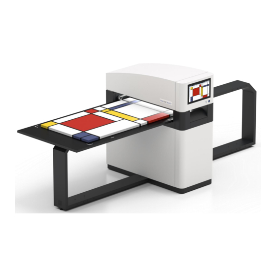
Best Practices WideTEK 36ART Page 6 of 26 4. Concept of the WideTEK 36ART The unique concept of a WideTEK 36ART is formed around three major elements. 4.1. Scanner Main Body The WideTEK 36ART’s main body controls a lightweight scanner table which is moved through the scanner’s body via a set of rubber wheels, placing the camera position at the stable part of the scanner. -
Page 7: Scan Table Position
Best Practices WideTEK 36ART Page 7 of 26 5. Scan Table Position The scanning table is a unique design and is very different from conventional designs. This makes it necessary to explain its features and the logic behind the scan table design. 5.1. - Page 8 Best Practices WideTEK 36ART Page 8 of 26 Fig. 2 Never place objects on the runway Fig. 3 Correct placement of object ATTENTION! Never put any objects on the runway. Although the motors are torque limited to avoid harm to persons, the table will have enough force to push anything (cups, bottles, phones, tablets and scanning objects) over the edge of the runway.
-
Page 9: Insert/Remove Scanning Table Without Tools
Best Practices WideTEK 36ART Page 9 of 26 5.3. Insert/Remove Scanning Table without Tools The scan table for the scanning objects can be inserted and moved on the scanner by hand. The right side of the scan table must be inserted first. The right side can be identified via the two additional white lines across the shorter edge of the table. -
Page 10: Location And Weight Of Objects
Best Practices WideTEK 36ART Page 10 of 26 5.4. Location and Weight of Objects The maximum weight you can put on the scanning table is 10Kg or 22lbs. Proper operation of the scanning table is guaranteed if the weight is spread out to the sides so that the center of the weight is over the runway, which supports the middle of the table. -
Page 11: The Control Panel
Best Practices WideTEK 36ART Page 11 of 26 6. The Control Panel The scanner features full user control of the scan table position, the scanner’s height and the focus methods used. The control panel can be invoked from the main screen here. As long as the control panel is active, the line lasers are switched on and measurements are performed. -
Page 12: Head Movement Control
Best Practices WideTEK 36ART Page 12 of 26 Fig. 8 Control panel head 6.2. Head Movement Control The head of the WT36ART can be raised by 100mm (appr. 4”) to accommodate for objects that are thicker. In the lowest position, clearance is already 100mm which means that objects who´s scanning surface is at the table level can have a frame or other obstructing parts up to 100mm. -
Page 13: Auto Focus Control
Best Practices WideTEK 36ART Page 13 of 26 6.3. Auto Focus Control Auto Focus function uses a laser assisted distance measurement of the object relative to the focal plane of the camera, which moves up and down with the head position. Fig. -
Page 14: Correct Positioning For Auto Focus
Best Practices WideTEK 36ART Page 14 of 26 6.4. Correct Positioning for Auto Focus The scanner has two lasers which are located between the three cameras. The laser lines are visible by both cameras, which allows measuring the heights of the object. These lasers are used by the Autofocus function. -
Page 15: Scan Start And Length Control
Best Practices WideTEK 36ART Page 15 of 26 6.5. Scan Start and Length Control When the scanner has been powered up and the scanning table is in the start position, the scanner is ready to scan. The object must be put under the camera and moved close to the white alignment edges which define the start and the width of the scan. -
Page 16: Software Stitching
Because a stitching error of more than one pixel is visible to the human viewer, more has to be done to correct stitching artifacts. All Image Access scanners which have two or more cameras feature an Adaptive 2D stitching function. -
Page 17: Various Scanning Scenarios
Best Practices WideTEK 36ART Page 17 of 26 8. Various Scanning Scenarios 8.1. Scanning Thin Objects Thin Object Examples Examples of thin objects are paper based objects, plastic foils, fabric etc. with a thickness of not more than 1mm (40mils). All necessary settings can be made in the control panel. Position Position the object as described in the previous chapter. -
Page 18: Artifacts Scanning Thin Objects
Best Practices WideTEK 36ART Page 18 of 26 8.2. Artifacts Scanning Thin Objects As long as the surface of the object in the vicinity of the lasers is smooth, there will be no artifacts. If another object is laying on top of the object to be scanned and caught by a laser set to Auto Focus, the laser will assume that the surface is closer and will correct the resolution causing a distortion. -
Page 19: Scanning Thick Objects
Best Practices WideTEK 36ART Page 19 of 26 8.3. Scanning Thick Objects Thick Object Examples Examples of thick objects are fine art on canvas, plastic foils, hardwoods, tiles, etc. All necessary settings can be made in the control panel. Position Position the object as described in the previous chapter. -
Page 20: Artifacts Scanning Thick Objects
Best Practices WideTEK 36ART Page 20 of 26 8.4. Artifacts Scanning Thick Objects Fine art on canvas should be scanned without the frame. If there is enough clearance, it can be scanned with the frame but you will see artifacts on the frame due to the Auto Focus. When the lasers hit the frame, they measure a shorter distance to the frame and will therefore correct the size distortion so that the width of the image is slightly reduced to scale it back to 300 or 600dpi. -
Page 21: Scanning Structured Objects
Best Practices WideTEK 36ART Page 21 of 26 8.5. Scanning Structured Objects Structured Object Examples Examples of structured objects are tiles, woodwork and art consisting of different layers or objects on top of each other. All necessary settings can be made in the control panel. Position Position the object as described in the previous chapter. -
Page 22: Artifacts Scanning Structured Objects
Best Practices WideTEK 36ART Page 22 of 26 8.6. Artifacts Scanning Structured Objects As long as the surface of the object in the vicinity of the lasers is smooth, there will be no artifacts. If another object is laying on top of the object to be scanned and caught by a laser set to Auto Focus, the laser will assume that the surface is closer and will correct the resolution causing a distortion. -
Page 23: D Texture Scanning
-2. Negative values simulate a light source shining from the bottom which leaves a rather unnatural impression. Fig. 27 3D scan at negative 3D The WideTEK ART has a special setting called Anti Reflection which can be selected under the 3D Light button. -
Page 24: The Perfect Illusion
Best Practices WideTEK 36ART Page 24 of 26 9.1. The Perfect Illusion Fig. 29 Image of an oil painting... - Page 25 Best Practices WideTEK 36ART Page 25 of 26 The WT36ART uses different light scenarios in a single scan and can generate many images from a single scan. Almost all parameters can be changed without the need to physically rescan the object, as long as the illumination mode was 3D.
-
Page 26: Optional Table Extension
Hatzfelder Str. 161-163 2511 Technology Drive, Suite 109 42281 Wuppertal, Germany Elgin, IL 60124, USA Phone: +49 202 27058-0 Phone: +1 (224) 293-2585 www.imageaccess.de www.imageaccess.us Technical changes, errors and omissions excepted. All information subject to change. © Image Access GmbH 2018...
Need help?
Do you have a question about the WideTEK Art and is the answer not in the manual?
Questions and answers