Menvier Security TS400 Installation & Programming Instructions
Intruder alarm control panels
Hide thumbs
Also See for TS400:
- Installation & user manual (11 pages) ,
- Operating instructions manual (9 pages) ,
- Installation instructions (2 pages)

Related Manuals for Menvier Security TS400


Summary of Contents for Menvier Security TS400
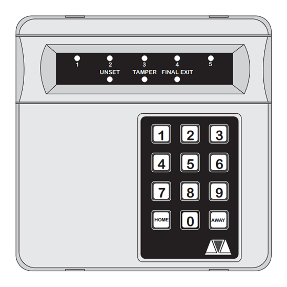
- Page 1 TS400 & TS410 Intruder Alarm Control Panels UNSET TAMPER FINAL EXIT HOME AWAY Installation & Programming Instructions...
-
Page 2: Table Of Contents
Initial Power-Up ..... . . 13 TS400 Features ..... . . 3 TS410 Features . -
Page 3: Introduction
TS400/TS410 Installation Instructions Overview Overview Introduction Specifications The TS400 and TS410 are 6 zone microprocessor TS400 Control Panel based intruder alarm control panels with 5 240V ±10% 50Hz Input Voltage: programmable zones and a dedicated Final Exit Current: 40mA (normal) 85mA (alarm) zone. -
Page 4: Planning The Installation
Planning The Installation General TS410 Control Panel The TS400 and TS410 are flexible systems, but care The TS410 control panel is blind panel and as such must be taken in planning the installation to it can positioned out of view, normally in a provide maximum protection with minimum cupboard under the stairs. -
Page 5: Detection Devices
TS400/TS410 Installation Instructions Planning The Installation Detection Devices Smoke/Heat Detectors 12V Smoke or heat detectors may be connected There are several types of detection devices to the system to provide additional protection available which are suitable for domestic against fire. When activated a distinctive internal... -
Page 6: System Installation
System Installation TS400/TS410 Installation Instructions System Installation Installing the TS400 Control Panel 4. Re-position the base and secure to the wall using not less than 30mm x No 10 screws. 1. Remove the screw from the top of the control panel and lift away the front cover. -
Page 7: Mains Connection
The TS400 and TS410 are equipped with inside the control panel. a "Battery Protection" circuit so that if a battery is accidentally reverse connected or its voltage is below 4V, a tamper alarm is generated. -
Page 8: Pcb Layout
HOME AWAY Leads to transformer A.C. Figure 3 TS400 & TS410 Connection Diagram Bell Fuse 1 - 5 Indicator LEDs This 1 Amp fuse protects the supply to the external These red indicator LEDs indicate the alarm status sounder/bell. of zone 1 - 5. Note these are not fitted on the TS410. -
Page 9: Multiple Detectors On The Same Zone
TS400/TS410 Installation Instructions System Installation To tamper loop for other zones Connecting several flush contacts per zone Flush Contact Flush Contact To tamper loop for other zones Connecting several suface contacts per zone Surface Contact Surface Contact Program [RST-] as... -
Page 10: Wiring Example
System Installation TS400/TS410 Installation Instructions Wiring Example External Sounder TS400 / TS410 TRIGGER - ALM - STROBE - RST - HOLD OFF + TRG - HOLD OFF - STB- TAMPER RETURN - TMP - ALARM TAMPER To ZONE 1 Terminal strip... -
Page 11: Installing A Remote Keypad
TS400/TS410 Installation Instructions System Installation the last or furthest remote keypad does not Installing a Remote Keypad exceed 50 metres). Ensure that the mains and battery power has been disconnected and proceed as follows: 7. Carefully reattach the front cover assembly to the remote keypad base ensuring that all 1. -
Page 12: Extension Loudspeakers
System Installation TS400/TS410 Installation Instructions Extension Loudspeakers Aux 12V Power A 16Ohm extension loudspeaker can be The auxiliary 12V terminals provide a permanent connected between the [L/S-] and [AUX 12V+] 12V supply for detectors which require a low terminals. R37 (located in the top left hand corner voltage supply e.g., PIRs, vibration detectors,... -
Page 13: Initial Power-Up
TS400/TS410 Installation Instructions System Installation Initial Power-Up On the TS410 you MUST connect the earth 1. Place a small screwdriver blade between the bonding cable from the front cover to the pins on the control panel PCB, marked spade connection point, see figure 2. -
Page 14: Programming
Programming TS400/TS410 Installation Instructions Programming Programming Menus There are two programming menus within the system. The engineer’s programming menu and the user programming menu. The figure below shows the structure of both programming menus, however the engineers programming menu is only covered in full detail within this manual. For full details on the user options see "User Operating Instructions". -
Page 15: Program Zones
(Home) condition it will start the entry timer if activated. View Event Log The TS400 will store up to 4 alarm activation events Keyswitch Zone 3 can be programmed as a keyswitch zone, within the memory log. -
Page 16: Exit Time
Programming TS400/TS410 Installation Instructions Exit Time Bell Duration Time This timer sets the delay between the user initiating This timer controls the duration of the external the setting procedure and the system actually sounder when the system is triggered into a full setting. -
Page 17: Remote Reset Number
TS400/TS410 Installation Instructions Programming Setting Mode Remote Reset Number The system can be programmed to set using The "Engineer Reset" option can be overridden by ether: the user, operating the "Remote Reset" facility. If an alarm is generated the system will respond with Timed Exit: The system will set when the exit timer a four digit "seed"... -
Page 18: Keyswitch Operation
Programming TS400/TS410 Installation Instructions Keyswitch Operation Returning to the Unset Mode The operation of the keyswitch (zone 3) can be Once all the engineer programming is completed programmed as either: the system can be returned to the unset mode by pressing the [0] key. -
Page 19: Testing & Fault Finding
TS400/TS410 Installation Instructions Testing & Fault Finding Testing & Fault Finding Testing the System Fault Finding Once the system has been installed and fully If you have carefully followed the installation and programmed it can be tested. Before performing wiring instructions and carried out the various... -
Page 20: Chart 1 - Zone Faults
Testing & Fault Finding TS400/TS410 Installation Instructions Chart 1 - Zone Faults Enter 4 digit engineer code and then press 3 to select walk test mode Remove control panel front cover Permanent Zone Detectors Fail To and disable the case... -
Page 21: Chart 2 - System Will Not Set
TS400/TS410 Installation Instructions Testing & Fault Finding Chart 2 - System Will Not Set Enter 4 digit engineer code and then press 3 to select walk test mode Deactivate all detectors & contacts (e.g. close doors etc.) No zone LED's on Zone LED on and and sounder is off. -
Page 22: Chart 3 - External Sounder Faults
Testing & Fault Finding TS400/TS410 Installation Instructions Chart 3 - External Sounder Faults Check PA buttons are not depressed. Ensure that the system is in the unset mode. External Siren External siren will not trigger when sounds continuously. performing a Bell Test. -
Page 23: Installation Records
TS400/TS410 Installation Instructions Installation Records Installation Records Zone Programming Zone Type Location Chime Home Config. Alarm / Access On / Off Armed / Omitted Alarm / Access On / Off Armed / Omitted Alarm / Keyswitch On / Off Armed / Omitted... - Page 24 Function Action LEDs Z1 = Access Z1 = Alarm Z2 = Access Z2 = Alarm Press [1] - [5] to toggle Zone Types LEDs on/off. Z3 = Keyswitch Z3 = Alarm Press [0] to end Z4 = Fire Z4 = Alarm Z5 = PA Z5 = Alarm Press [1] for newest event...
Need help?
Do you have a question about the TS400 and is the answer not in the manual?
Questions and answers