Table of Contents
Advertisement
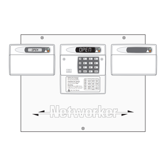
Intruder Alarm Control Panel
OPEN
Installation & Programming
TS700
_
~
OPEN
A
B
C
D
Sett ing the Syst em
Ent er your pa ss code XXXX
th en lea v e th e pro tec t ed a re a.
Unsetting the System
Go dir e ct ly to t he ke yp ad and
en ter you r p as scod e XXXX .
Resetting
Ent er your pa ss code XXXX f ollow ed
by EN T the n 3. Te leph on e you r a lar m
com pan y and follow th eir instr uct io ns.
See U ser Manual
!
Instructions
_
~
1
2
3
4
5
6
7
8
9
0
ENT
ESC
A
1
2
3
Part Set
BELL TEST
WALK TEST
R ESET
B
4
5
6
Part Set
NEW C ODE
CHIME
24 Hr OMIT
C
7
8
9
Part Set
ZONE O MIT
SILENT
D
ENT
0
ESC
FU LL SET
_
~
Advertisement
Table of Contents

Related Manuals for Menvier Security TS700


Summary of Contents for Menvier Security TS700
- Page 1 TS700 Intruder Alarm Control Panel OPEN OPEN Sett ing the Syst em Ent er your pa ss code XXXX th en lea v e th e pro tec t ed a re a. Part Set BELL TEST WALK TEST R ESET...
-
Page 2: Table Of Contents
Contents Overview Change Engineer's Passcode ..23 Configure Chime Circuits....23 Introduction ......3 Configure 24 Hour Omit Group . -
Page 3: Introduction
All system data stored in a Non-Volatile Memory (NVM) Remote Keypads and LECs The TS700 system will accept three types of remote keypads: The NETLED remote keypad has a 4 x 7 segment LED display and a power indicator. The NETSTAR remote keypad has a 8 character LCD display and a power indicator. -
Page 4: Specifications
(DP / EOL) (DP / EOL) (DP / EOL) (DP / EOL) Printer 8 Zones Bell output (DP / EOL) Strobe output Digi outputs 1- 8 Number of Zones =10 to 16 Outputs 1- 4 Figure 1. TS700 System Configuration... -
Page 5: System Installation
TS700 Installation Manual System Installation System Installation Cable Routing When installing cables ensure that detection, remote keypad, bell and mains cables are kept separated from each other and that panel internal wiring is clear of the main PCB. Installing The Control Panel Proceed as follows: Open the control panel by removing two screws from the front cover. -
Page 6: Pcb Layout
DIGI-MODEM Digicom Outputs Programmable @ 100mA SPKR Auxiliary Tamper Extension loudspeaker BATTERY FAULT External sounder connections Programmable Detection Circuits 1 - 8 Bell fuse (1A) Aux. fuse (1A) Mains connection POWER Mains fuse (200mA) Figure 2. TS700 Main PCB Layout... -
Page 7: Wiring Detection Circuits
TS700 Installation Manual System Installation Wiring Detection Circuits All detection circuits may be wired as "End of line" (EOL) or "Double Pole" (DP). Both methods can be used on the same system. Double Pole (DP) The DP method requires the following: The detector alarm and tamper contacts are connected to the zone and tamper terminals respectively. -
Page 8: Installing Remote Keypads And Lecs
System Installation TS700 Installation Manual Installing Remote Keypads and LECs The following types of devices may be connected to the control panel: NETLED 4 x 7 Segment LED display. NETSTAR 8 Character Starburst LCD display. NETARM Remote Arming station (Power LED & programmable "Function" LED). - Page 9 TS700 Installation Manual System Installation 100m (Max.) I/D=1 I/D=2 I/D=3 I/D=4 Remote Remote Remote Remote Keypad Keypad Keypad Keypad Spare Core or LEC or LEC or LEC or LEC A B C D E A B C D E A B C D E...
-
Page 10: Installing A Plug-On Digicom
TS700 Installation Manual Installing a Plug-on Digicom A digicom type DC54 or DC58 can be fitted in the base of the TS700 main panel. The unit should be fitted in accordance with the installation instructions supplied with it and connected to JP3. -
Page 11: Sounder Connections
TS700 Installation Manual System Installation Sounder Connections The external and internal sounder can be connected to the control panel using the following connections: AUX TAMP These terminals provide tamper protection to auxiliary devices such as power supplies, extension loudspeaker units etc. -
Page 12: Installing Output Modules
500 metres away from the main panel. They may be fitted inside the TS700 by fitting posts and securing them to the base. The output module should be used and connected in accordance with the output module instructions provided (Figure 8). -
Page 13: Programmable Outputs
TS700 Installation Manual System Installation Programmable Outputs The TS700 has many programmable outputs which can be used to drive relays, LED’s etc. Each output can be programmed for a different function, see "Programmable Output Types" on page Control Panel Outputs... -
Page 14: Pre Power-Up Checks
System Installation TS700 Installation Manual Pre Power-Up Checks Once the system is installed, but prior to powering-up give the system one final check to ensure that: The wiring conforms to the requirements detailed in this manual and that all interconnections are correct (A to A, B to B etc.). -
Page 15: Factory Default Parameters
TS700 Installation Manual System Installation Factory Default Parameters Engineer's code 1234 Master User 5678 code Panel and Walk Test Courtesy Switched Detector Code Code Code Code Remote Outputs Light Reset Accepte Accepte Accepte Accepte Digicom Outputs Fire Alarm Eng on... -
Page 16: Programming
Programming TS700 Installation Manual Programming Engineer Menu 1 Engineers menu 1 is selected when the engineer's passcode is entered during the unset condition. The engineer may leave engineer menu 1 by pressing the [ESC] key. The system will return to the unset condition but the remote keypads will show: "ENG ON SITE". - Page 17 TS700 Installation Manual Programming Type Function Bell On Active when the external Bell trigger is activated. Strobe Active when the Strobe trigger is activated. SW12 Used to latch devices in an alarm. Active when the system is set. Detector Reset Used to power devices which require power to be removed to reset them.
-
Page 18: Detection Circuits And Attributes
Programming TS700 Installation Manual Detection Circuits and Attributes Detection circuits 1 to 8 for the panel and 9 to 16 for the remote keypads/ LECs are programmed as follows: Ensure that "Engineer Menu 1" is selected. CT. - - Press 4 to select the Circuits and Attributes option. -
Page 19: System Timers
TS700 Installation Manual Programming Display Attribute Type Access - Circuits programmed with this attribute are automatically isolated during the entry procedure to allow a "walk through" route for the user to access the remote keypad. When the system is part set activation of a circuit with the "Access" attribute will start the entry timer. -
Page 20: Setting Modes
Programming TS700 Installation Manual Settling Time 0-199 sec When setting the system by "Final Exit" or "Exit Terminator", detectors that are on the exit route sometimes take 3-4 seconds to settle after activation. The delay programmed in this timer is used to allow these detectors to settle before the system or area is set. -
Page 21: System Print
TS700 Installation Manual Programming Select new setting mode by pressing: 1 for Final Exit 2 for Exit Terminator 3 for Timed Exit 0 to `toggle' between all three options When the display shows the required setting press [ to accept. -
Page 22: Engineer's Menu 2
Programming TS700 Installation Manual Bell output is set for SAB Bell output is set for SCB Disable Master User from menu 2 options 4-9 Master user has access to all options in menu 2 Fire Signalled when Unset/Part Set/Full Set... -
Page 23: Change Date
TS700 Installation Manual Programming Change Date The system calendar may be changed by entering the date as four digits representing the day and month e.g., 0207 is the 2nd July. ---- Ensure that "Engineer Menu 2" is selected. Press 3 to select the Change Date option. -
Page 24: Print System Log
Programming TS700 Installation Manual Print System Log A printer may be connected to produce a print-out of the last 200 system events. Ensure that "Engineer Menu 2" is selected. Press 7 to select the Print Log option. Enter the number of events to be printed. - Page 25 TS700 Installation Manual Programming Action Alarm (Alarm output activated) Lid Tamper or SAB tamper Ac** Access Passcode (User code **entered System Open (unset) with the last two digits reversed) AD.** Alarm Delayed (the system is part set and Omits Removed circuit ** was activated) Au.**...
-
Page 26: Appendices
Appendices Domestic Part-Set Application Example The TS700 control panel can be configured so that only part of the system is armed. The following example illustrates how the TS700 alarm system is configured so that it protects different areas of a three bedroom detached house. -
Page 27: Programming Procedure
TS700 Installation Manual Appendices Using the plan of the typical three bedroom house, the following part-set arrangements are required by the occupants of the house: Full Set All circuits to be armed. Part-set Group A Circuits 9 and 10 to be omitted. This is required for normal night setting when everyone is in the house and have retired to bed. - Page 28 "Part-set Code A" will set and unset the circuits assigned as "Omitted" in "Part-set Group A". When configuring the TS700 system to use "Part-set Codes", it is important to think of the system from the full-set state. When a part-set code is entered the circuits that have been assigned as "Omitted"...
-
Page 29: Programming Procedure
TS700 Installation Manual Appendices Programming procedure First, imagine the system is fully set. When "Part-set Code A" is entered certain circuits are required to be "Omitted" whilst others remain "Armed". Create a table listing the circuits that are to be "Omitted" (O) when "Part-set Code A" is entered. The circuits that will not be omitted must therefore remain "Armed"... -
Page 30: Installation Record
Installation Record TS700 Installation Manual Installation Record Circuit Programming Location Type Access D-Knock Test Omit Reset PS A PS B PSC 24hr Outputs Output Panel & remotes Digicom outputs Digicom Channel System Timers Re-arms: Settling: Digi Delay: Exit Time: Entry Time:... - Page 32 Menvier Security Ltd. Kenn Road, Clevedon, Bristol BS21 6LH, England Tel: +44 (0)1275 870078 Fax: +44 (0)1275 343453 Email: menvier.security@dial.pipex.com Internet: http//:www.menviersecurity.co.uk 18606 Drg No. 33:2159:00 Issue 01 Doc. 01 August 98...
Need help?
Do you have a question about the TS700 and is the answer not in the manual?
Questions and answers
Trying to program to allow end user to omit zones
To program the Menvier Security TS700 to allow the end user to omit zones:
1. Ensure that "Engineer Menu 2" is selected.
2. Press 6 to select the 24 Hour Omit Group option.
3. Circuits will be displayed as O (Omitted) or A (Armed).
4. Press 0 to toggle between Armed and Omitted for each circuit.
5. Press [ ] to accept the selection and move to the next circuit.
6. A low tone indicates that the circuit cannot be omitted.
7. Press ENT to confirm and exit.
This configuration allows the user to omit selected 24-hour circuits when using the 24-hour omit option in User Menu 1, option 6.
This answer is automatically generated