Menvier Security TS400 Installation & User Manual
Hide thumbs
Also See for TS400:
- Installation & programming instructions (24 pages) ,
- Operating instructions manual (9 pages) ,
- Installation instructions (2 pages)

Related Manuals for Menvier Security TS400


Summary of Contents for Menvier Security TS400
- Page 1 TS400 & TS410 Installation & User Guide Compatible Equipment TS400 REM - Remote Keypad 9040 - Loudspeaker SD1+ - Speech Dialler 1 of 10 496522 Issue A TS400 & TS410...
-
Page 2: Specifications
TS400 & TS410 Overview Introduction Specifications TS400 Control Panel The TS400 and TS410 are 6 zone microprocessor based Input Voltage: 240V ±10% 50Hz intruder alarm control panels with 5 programmable Current: 40mA (normal) 85mA (alarm) zones and a dedicated Final Exit zone. The ease of... -
Page 3: System Installation
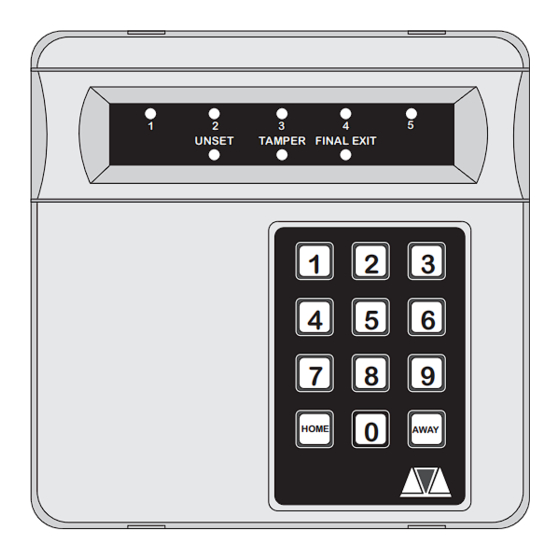
HOME AWAY Leads to transformer A.C. Figure 1. TS400 & TS410 Connection Diagram Bell Fuse Zones 1 - 5 Indicator LEDs This 1 Amp fuse protects the supply to the external These red indicator LEDs indicate the alarm status of sounder/bell. -
Page 4: Wiring Example
TS400 & TS410 Wiring Example TS400/TS410 EXTERNAL SOUNDER ALM - TRIGGER - RST - STROBE - TRG - HOLD OFF + STB - HOLD OFF - TAMPER RETURN - TMP - TAMPER TERMINAL STRIP ALARM To ZONE 1 (NOT SUPPLIED) -
Page 5: Extension Loudspeakers
TS400 & TS410 Installing a Remote Keypad Extension Loudspeakers Ensure that the mains and battery power has been A 16 Ohm extension loudspeaker can be connected disconnected and proceed as follows: between the [L/S-] and [AUX 12V+] terminals. R37 (located in the top left hand corner of the PCB) can be... -
Page 6: Initial Power-Up
TS400 & TS410 (located just below the LEDs). This will ensure the Aux 12V Power factory defaults are loaded as shown below: Engineer Code 1234 The auxiliary 12V terminals provide a permanent 12V supply for detectors which require a low voltage supply... -
Page 7: Key Functions
TS400 & TS410 Key Functions Engineer’s Reset 1. Enter the Engineer’s Code default 1234. You are now in Engineer’s Mode. 2. Press 0 to return to unset. Loading Defaults 1. Power down panel mains and battery. 2. Place a small screwdriver blade between the pins on the control panel PCB, marked Factory Restart. - Page 8 TS400 & TS410 Engineer’s Quick Reference Programming Chart Function Action LEDs Z1 = Access Z1 = Alarm Press [1] - [5] to toggle LEDs Z2 = Access Z2 = Alarm Zone Types on/off. Z3 = Keyswitch Z3 = Alarm Press [0] to end...
-
Page 9: Change Passcode
TS400 & TS410 User Options Menu UNSET TAMPER FINAL EXIT Enter first 3 digits of passcode then HOME (e.g., HOME Unset UNSET TAMPER FINAL EXIT Flashes = Bell Test = Walk Test = Change Passcode 1 = Change Passcode 2... - Page 10 TS400 & TS410 This page intentionally left blank 10 of 10 TS400 & TS410 496522 Issue A...
Need help?
Do you have a question about the TS400 and is the answer not in the manual?
Questions and answers
After setting for away, when I returned after two days, no lights were showing on the panel, what does this indicate?