Menvier Security TS690 Installation & Programming Manual
Intruder alarm control panels
Hide thumbs
Also See for TS690:
- Installation & programming manual (60 pages) ,
- Installation & programming manual (60 pages) ,
- Operator's manual (48 pages)
Table of Contents
Advertisement
Quick Links
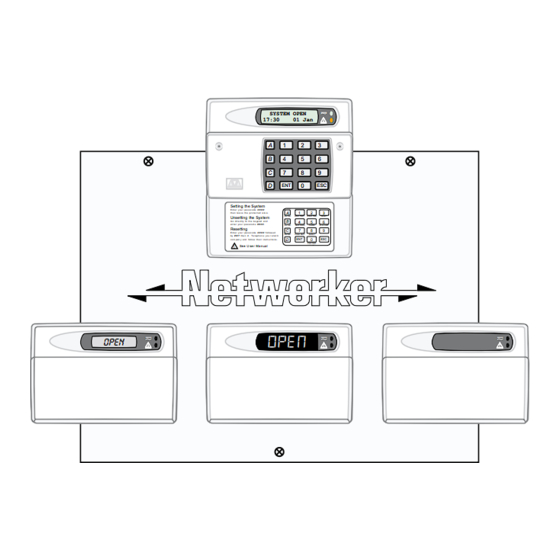
TS690 & TS690ID
Intruder Alarm Control Panels
_
~
OPEN
Installation & Programming
_
~
SYSTEM OPEN
17:30
01 Jan
A
1
2
3
5
B
4
6
C
7
8
9
D
0
ENT
ESC
Sett ing the Syst em
E n t er y ou r pa s s c o de X X X X
A
1
2
3
th en l ea v e th e p r o tec t e d a re a.
Unsetting the System
Part Set
B ELL TES T
W ALK TEST
RE SET
B
4
5
6
G o di r e ct ly to t h e k e yp ad an d
en te r y ou r p as s c o d e X X X X .
Part Set
NE W CODE
CHIME
24 Hr OMIT
Resetting
C
7
8
9
E n t er y ou r pa s s c o de X X X X f o ll ow e d
Part Set
ZONE O M IT
SILENT
by E N T the n 3 . Te l eph o n e y o u r a l ar m
D
ENT
0
ESC
c o m pan y a nd fo ll o w th ei r i ns tr uc t io ns .
FULL S ET
Se e U se r Ma n ua l
!
_
_
~
~
OPEN
Engineers menu 2
Select option :-
Manual
_
_
~
~
Engineers menu 2
Select option :-
Advertisement
Table of Contents

Subscribe to Our Youtube Channel
Related Manuals for Menvier Security TS690


Summary of Contents for Menvier Security TS690
-
Page 1: Engineers Menu 2
TS690 & TS690ID Intruder Alarm Control Panels SYSTEM OPEN 17:30 01 Jan Sett ing the Syst em E n t er y ou r pa s s c o de X X X X th en l ea v e th e p r o tec t e d a re a. -
Page 2: Table Of Contents
TS690 & TS690ID Installation Manual Contents Overview Wiring A Biscuit to a PIR ....16 Wiring a Biscuit to a Panic Button ..17 Introduction . - Page 3 TS690 & TS690ID Installation Manual Clear & Relearn ID Devices ... 37 Alarm Abort Operation ....51 Add ID Devices .
-
Page 4: Introduction
Each remote keypad has two sites. The TS690 system can monitor 6 zones locally detection circuits and a single switched -ve and up to 8 zones via remote keypads or LECs. All output. -
Page 5: System Architecture
(DP / EOL) DCI Connection Bell output Biscuit 30 ID zones Biscuit I.D. Loop output Strobe Digi outputs 1- 5 Digi Modem (Optional) Number of Zones = 2 to 38 Outputs 1- 3 Figure 1. TS690 & TS690ID System Architecture... -
Page 6: Specifications
TS690 & TS690ID Installation Manual Specifications Control Panel Output: Switched -ve @100mA Part No.: TS690 - 6 to 14 zones Dimensions: 150(W) x 104(H) x 30(D) mm TS690M - with DC6 modem Material: 3mm Polycarbonate TS690ID - 2 to 38 zones... -
Page 7: System Installation
A B C D E A B C D E A B C D E A B C D E Control Panel Remote Network Power for Power for Power for Power for detectors detectors detectors detectors Figure 2. TS690 & TS690ID Remote Network Wiring... -
Page 8: Id Loop Wiring (Ts690Id Only)
System Installation TS690 & TS690ID Installation Manual ID Loop Wiring (TS690ID Only) If a different type of cable is used, the distances should be recalculated. e.g., if 7/0.4mm cable is Each ID device is connected across a two-wire ID used, a single run of 80 metres would support 30 loop. -
Page 9: Control Panel Installation
Mains Cable Fused Terminal Mains Entry Block 315mA Transformer Printed Circuit Board Battery Spade connection (PCB) Position for earth lead to front cover Figure 4. TS690 & TS690ID Control Panel Layout... -
Page 10: Control Panel Pcb Layout
(SELV) (Only Fitted on TS690) 21V A.C. from mains transformer (SELV) Telephone connections (TNV) Aux 12V & I.D. Loop (SELV) (Only Fitted on TS690ID) DC6 Digi-modem (Only fitted on the TS690M & TS690IDM) Figure 5. TS690 & TS690ID Main PCB... -
Page 11: Connection Terminals & Indicators
TS690 & TS690ID Installation Manual System Installation Connection Terminals & Indicators A removable nonvolatile memory (NVM) Connection terminals on the TS690 / TS690ID are device that stores all system program described as ether “Safety Extra-Low Voltage” parameters and the 700 log events. -
Page 12: Mains Connection
Remote I/D. it to function during a mains fail condition. The Used to select the remote keypads address. TS690 & TS690ID is equipped with a “Battery (ENG = Engineer). Protection” circuit so that if a battery is accidentally ... -
Page 13: Installation Procedure
TS690 & TS690ID Installation Manual System Installation “ Tamper Switch. Installation Procedure. Remote Keypad case tamper Always ensure that all power (mains and ” ENT Key Disable. battery) is removed before making any If the “ENT” key is enabled the remote keypad can connections to the remote keypad. -
Page 14: Keypad Loudspeaker Connections
System Installation TS690 & TS690ID Installation Manual TS700 LEC Installation 5. Set the “ENT KEY DISABLE” jumper link to the required position. The TS700 LEC (Local Expansion Card) is connected to the “Remote Network” and provides 6. Set the “WARD SOUNDER CONTROL” jumper link two additional programmable detection circuits to the required position. -
Page 15: Wiring Detection Circuits
TS690 & TS690ID Installation Manual System Installation 4. Connect “Remote Network” cables and Normally open devices such as pressure pads detection circuit cables to the appropriate and exit terminator buttons are connected between the zone and tamper terminals. terminals, see Figure 10 If the detection circuit is not used links can be 5. -
Page 16: Wiring Id Biscuits
System Installation TS690 & TS690ID Installation Manual 500 metres or 100 Ohms When the tamper switch is opened, the ID biscuit becomes off line and a tamper alarm is 4K7 = Yellow, Violet, Red 2K2 = Red, Red, Red generated by the control panel. If the alarm... -
Page 17: Wiring A Biscuit To A Panic Button
TS690 & TS690ID Installation Manual System Installation External Sounder Connections Wiring a Biscuit to a Panic Button The figure below shows typical wiring configuration The following terminals have been provided to for a standard panic button. allow connections to an external sounder:... -
Page 18: Extension Loudspeakers
System Installation TS690 & TS690ID Installation Manual Extension Loudspeakers REM RESET If the system is programmed for “Engineer Reset”, Up to two extension loudspeakers can be then after a full alarm the system will require connected across the [SPK+] and [H/O-] terminals resetting, normally this is done by the engineer or on the control panel PCB. -
Page 19: Application
TS690 & TS690ID Installation Manual System Installation Application Please ensure that cabling to the The DC6 digital communicator/modem is suitable telephone line connections (TNV) are for connection to the following types of telephone routed well away from the detection line:... -
Page 20: Installation
System Installation TS690 & TS690ID Installation Manual DC54 & DC58M Installation Installation A plug-on digital communicator DC54, DC58 or For your safety, installation of the DC6 DC58M may be fitted inside the control panel to MUST be carried out in the sequence... -
Page 21: Connecting A Printer
System Installation Connecting a Printer Using the CPA6 Printer The TS690 and TS690ID supports two type of 6. Plug the CPA6 printer directly on to the PRINTER printers, the CPA6 printer (no longer available) and plug (JP1) on the main control panel PCB. -
Page 22: Pre Power-Up Checks
System Installation TS690 & TS690ID Installation Manual +ve O/P Aux 12 V Relay available from Relay available from Diode (IN418) Diode (IN418) (Programmed as Alarm / Bell / etc) RS components RS components P/No. 346-946. P/No. 346-946. Capable of switching... -
Page 23: Initial Power-Up
TS690 & TS690ID Installation Manual System Installation Initial Power-Up 3. With the ID loop still disconnected from the control panel, use a DVM to measure the To power the system for the first time: resistance between the following cores and 1. -
Page 24: Nvm Defaults
System Installation TS690 & TS690ID Installation Manual NVM Defaults Section Option Default Section Option Default User 00 Engineer 1234 22-Service Time 000 months User Codes System Timers User 01 Master 5678 23-Test Call At Panel Output 1 Walk Test Full Set... -
Page 25: Introduction
TS690 & TS690ID Installation Manual Engineer’s Menu 1 Engineer’s Menu 1 Enter Engineer's Introduction Passcode Engineers menu 1 is the first of two engineers 1 2 3 4 menus, which is selected when the engineer’s passcode is entered. The engineer may leave Engineers menu 1 “Engineer menu 1"... -
Page 26: Panel Outputs
Engineer’s Menu 1 TS690 & TS690ID Installation Manual Panel Outputs [1.1] Digicom Channels [1.3] Outputs 1-3 on the control panel and remote The 8 plug-on digicom channels can be keypad outputs 5-8 can be programmed to any programmed to any of the output types shown on of the output types shown on pages 26 to 28. - Page 27 TS690 & TS690ID Installation Manual Engineer’s Menu 1 Type/Description Type/Description 004 Walk Test 017 Part Set B Selected Activates when the "Walk Test" option is Activates when "Part Set B" is selected. selected and deactivates when the "Walk Test" Deactivates when the system is unset.
- Page 28 Engineer’s Menu 1 TS690 & TS690ID Installation Manual Type/Description Type/Description 032 Duress Alarm 044 General Fault Activates when a duress passcode is entered Activates during battery fault or when the and deactivates when the duress alarm is system is prevented from being set.
-
Page 29: Program Circuits
Program Circuits [1.4] set, activation of this circuit will start the entry timer. The TS690 can monitor up to 14 detection circuits, whereas the TS690ID can monitor up to 38 8 Exit Terminator detection circuits. Each circuit must be A circuit that is normally connected to a push... - Page 30 Engineer’s Menu 1 TS690 & TS690ID Installation Manual 2 Double Knock part-set condition. The “Entry” attribute can Circuits programmed with this attribute will only only be assigned to Night, 24hr and Final Exit cause an alarm condition if: circuit types. When assigned to a 24 Hour...
-
Page 31: System Timers
TS690 & TS690ID Installation Manual Engineer’s Menu 1 System Timers [1.5] count down. If a valid user passcode has not been entered when the timer reaches zero, The system timers are as follows: the internal sounders are activated and the 00 Abort Delay “2nd Entry”... - Page 32 Engineer’s Menu 1 TS690 & TS690ID Installation Manual 12 Monitor Dur. out from sending any more. Note: this does not This timer affects the duration of the “Timed affect the re-arm of the zone. This counter has Output” (No. 042). This timer has a working a working range of 000 - 199.
-
Page 33: Setting Modes
TS690 & TS690ID Installation Manual Engineer’s Menu 1 23 Test Call At Setting Modes [1.6] This timer is used in conjunction with timer 19, it The setting mode for full set and each part set can controls the hour at which a test call is sent to be configured to the following setting modes: central station. -
Page 34: Do System Print
Engineer’s Menu 1 TS690 & TS690ID Installation Manual Do System Print [1.7] Configuration [1.9] If a printer is connected to the control panel a print The configuration options are as follows: out of all system parameters can be obtained. 00 Bell is an SAB When programmed as “Yes”... - Page 35 TS690 & TS690ID Installation Manual Engineer’s Menu 1 08 Extended format 16 SET with AC off When programmed as “Yes" the plug-on When programmed as “Yes”, the system can digicom will report using Point ID extended b e s et wit hou t m ain s p ower . Whe n format.
- Page 36 Engineer’s Menu 1 TS690 & TS690ID Installation Manual 24 Monitor off hook 29 Keypad PA Silent When programmed as “Yes”, the plug-on When programmed as “Yes”, pressing 1 & 3 on digicom will monitor the telephone line for the remote keypad will generate a silent PA off-hook conditions (high security line alarm.
-
Page 37: Go To User Menu 1
TS690 & TS690ID Installation Manual Engineer’s Menu 1 Go to User Menu 1 [1.0] Add/Clear ID Devices (TS690ID) [1.A] This option allows the engineer to access “User This option allows the engineer to add and remove menu 1", the flowchart below shows the options ID devices from the system. -
Page 38: View Location Text (Lcd Only)
Engineer’s Menu 1 TS690 & TS690ID Installation Manual Starburst Engineers menu 1 Starburst ENGR 1 - E1 - Select Option :- Engineers menu 1 ENGR 1 - E1 - Select Options :- ID Devices >HHHHHHHHAAHH... 01 - 15 USE 16x2 >.... -
Page 39: Engineer's Menu 2
TS690 & TS690ID Installation Manual Engineer's Menu 2 Engineer's Menu 2 Introduction Engineers menu 1 Engineer's menu 2 is selected by pressing the [ENT] Select Option :- key whilst Engineer's menu 1 is selected. Each menu option can be selected by pressing the relevant “Hot key”. -
Page 40: View Circuits
Engineer's Menu 2 TS690 & TS690ID Installation Manual View Circuits [2.1] Set System Time [2.2] Each detection circuit may be viewed to The system time is displayed in a 24hr format on all ascertain its status. The circuit status conditions... -
Page 41: Change Passcode
TS690 & TS690ID Installation Manual Engineer's Menu 2 Change Passcode [2.4] Alter Shunt Group [2.6] This option allows the engineer to change their Circuits can be assigned to the shunt group. The passcode. The default passcode is 1234 but the... -
Page 42: Configure Part Sets
[2.8] View System Log [2.9] The TS690 and TS690ID can be configured to have The engineer can use this option to view the up to three parts set modes (Part Set A, Part Set B system log. The [A] and [C] keys allow you to scroll and Part Set C). -
Page 43: Log Event Codes
TS690 & TS690ID Installation Manual Engineer's Menu 2 Log Event Codes Starburst Description A.C. OFF AC OFF Mains power removed. A.C. ON AC RESTORED Mains power restored ALM SENT ACTION ALARM Alarm activated when system is part-set. ALARM 01-38 CA. 0 1-38 ALARM 01-38 Full alarm from circuit (01-38). -
Page 44: Log Event Codes
Engineer's Menu 2 TS690 & TS690ID Installation Manual Log Event Codes Starburst Description LID TAMP PANEL LID TAMPER Control panel lid removed. P.SET A/B/C PS. A /B/C PART SET A/B/C System Part-Set using one of the A, B, or C buttons. -
Page 45: Custom Text Menu (Lcd Only)
TS690 & TS690ID Installation Manual Engineer's Menu 2 LCD Only Starburst Engineers menu 2 Select Option :- Engineers menu 2 ENGR 2 - E2 - Select Option :- 1-CCT, 2-Banner 3-Location Call Number 1 Call back No. CALL NO.1 No . 1 Tel No. -
Page 46: Modem Password
Engineer's Menu 2 TS690 & TS690ID Installation Manual This option allows the Modem site number to be LCD Only programmed. The “Modem Site No.” is a 4 digit Engineers menu 2 number that is used as a site reference. When Select Option :- using the “Lineload”... -
Page 47: Digicom Tests
TS690 & TS690ID Installation Manual Engineer's Menu 2 LCD Only Digicom Tests Engineers menu 2 This option allows the engineer to test each Select Option :- channel on the plug-on digi-modem (DC6) and the five digi outputs on the main PCB. -
Page 48: Text Editing Keys
The TS790.STAR remote keypad is capable of displaying up to eight characters of text when it is keypad function as shown below: connected to the TS690/TS690ID control panels. However the text can only be entered using a TS900 LCD remote keypad or via Lineload 0 (Zero) software. -
Page 49: Appendices
TS690 & TS690ID Installation Manual Appendices Appendices Point ID Extended Reporting Point ID extended reporting is a new format which Code Description when used with the DC6 can be used to report Engineer program mode selected circuit ID data, user ID etc. The central station... - Page 50 Appendices TS690 & TS690ID Installation Manual Kitchen Dining Room Hall Garage Lounge Key: Passive Infra-Red Detector Bathroom Magnetic Contact Bedroom 2 Remote Keypad Control Panel Landing Bedroom 1 Bedroom 3 Figure 27. A Typical 3 Bedroom House...
-
Page 51: Part-Set Application Example
Part-Set Application Example Alarm Abort & Confirmation This application example shows how to configure Both the TS690 and TS690ID support “Alarm Abort” the part set buttons to set different areas of a 3 and “Sequential Confirmation”. The alarm abort bedroom house. -
Page 52: Setup New Users
Setup New Users feature can be disabled by the installation company or by making the first two digits of The TS690 and TS690ID allows up to 15 users to the passcode the same. operate the alarm system, each user is assigned a user type and 4 digit passcode. -
Page 53: Software History
TS690 & TS690ID Installation Manual Appendices Software History Version 2.4 ID line driver levels changed, see page 37 for Version 1.0 details. Initial software release. Operation of line fault timer (021) changed. When the timer is set to 199 the monitoring of Version 1.2... -
Page 54: Quick Reference Engineers Menus
Appendices TS690 & TS690ID Installation Manual Quick Reference Engineers Menus Engineers Menu 1 Options Page Options Page System Configuration Program Panel Outputs 1 = Panel Output 1 (relay) 00 = Bell is an SAB Bell is an SCB 2 = Panel Output 2 (-ve) -
Page 55: Output Types
TS690 & TS690ID Installation Manual Appendices Quick Reference Engineers Menus Engineers Menu 2 Output Types Output Type Output Type Options Page 000 Bell On 026 Comms Failed View Circuits A = Scroll Next Circuit 001 Strobe On 027 Comms Success... -
Page 56: Quick Reference User Menus
Appendices TS690 & TS690ID Installation Manual Quick Reference User Menus User Menu 1 User Menu 2 Options Options Bell Test View Circuits A = Scroll Next Circuit Walk Test C = Scroll Previous Circuit Remote Reset Set System Time Enter Reply code + ENT Enter time e.g. -
Page 57: Notes
TS690 & TS690ID Installation Manual Appendices Notes... - Page 58 Appendices TS690 & TS690ID Installation Manual Notes...
- Page 59 TS690 & TS690ID Installation Manual Appendices Notes...
- Page 60 Cooper Security Ltd. Security House, Xerox Business Park, Mitcheldean, Gloucestershire, GL17 0SZ. England Product Support Tel: +44 (0)1594 545556 Between 09:00 and 17:00, Monday to Friday. Product Support Fax: +44 (0)1594 545401. w ww.coopersecurity.co.uk 496494 Issue 2...
Need help?
Do you have a question about the TS690 and is the answer not in the manual?
Questions and answers