Menvier Security TS690 Operator's Manual
Intruder alarm control panels
Hide thumbs
Also See for TS690:
- Installation & programming manual (60 pages) ,
- Installation & programming manual (60 pages) ,
- Installation & programming manual (60 pages)
Table of Contents
Advertisement
Quick Links
TS690 & TS690ID
Intruder Alarm Control Panels
OPEN
Operators Manual
Se tt in g the S yst em
E n t er y ou r pa s s c o de X X X X
th en l ea v e th e p r o tec t e d a re a.
Unsetting the Syste m
G o di r e ct ly to t h e k e yp ad an d
en te r y ou r p as s c o d e X X X X .
Resetting
E n t er y ou r pa s s c o de X X X X f o ll ow e d
by E N T the n 3 . Te l eph o n e y o u r a l ar m
c o m pan y a nd fo ll o w th ei r i ns tr uc t io ns .
Se e U se r Ma n ua l
!
_
~
_
~
SYSTEM OPEN
17:30
01 Jan
A
1
2
3
B
5
4
6
C
7
8
9
D
ENT
0
ESC
A
1
2
3
Par t Set
B ELL TES T
W AL K TEST
RE SET
B
4
5
6
Par t Set
NE W CO D E
CH IME
24 Hr OMIT
C
7
8
9
Part Set
Z ON E O M IT
SILEN T
D
ENT
0
ESC
FUL L S ET
_
_
~
~
OPEN
Engineers menu 2
Select option :
_
_
~
~
Engineers menu 2
Select option :
Advertisement
Table of Contents

Related Manuals for Menvier Security TS690


Summary of Contents for Menvier Security TS690
- Page 1 TS690 & TS690ID Intruder Alarm Control Panels SYSTEM OPEN 17:30 01 Jan Se tt in g the S yst em E n t er y ou r pa s s c o de X X X X th en l ea v e th e p r o tec t e d a re a.
-
Page 2: Table Of Contents
Contents Set Date ....27 System Overview Setup New Users ... 28 Introduction ....3 User Types . -
Page 3: System Overview
The system comprises of a number of components linked to a central control unit which is concealed from view but accessible for maintenance. The TS690 can monitor from 6 to 14 detection circuits whereas the TS690ID can monitor from 2 to 38 detection circuits. -
Page 4: Remote Keypads
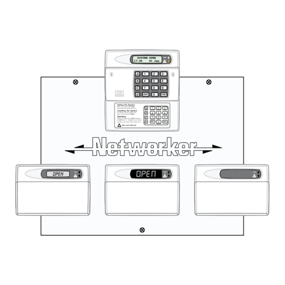
Remote Keypads Your alarm system can be operated from one or more remote keypads, which will have been strategically located within the protected premises. The remote keypads may be one of four types. Arming Station The remote arming station can only be used to full set, part set and unset your alarm system. -
Page 5: Starburst Keypad
Remote Keypads Starburst Keypad The Starburst remote keypad can be used to full set, part set and unset the alarm system. It also can be used for limited programming functions. � Starburst Display - Used to show the � system time along with other system �... -
Page 6: Operating Your Alarm System
User Types The TS690 and TS690ID can have up to 15 separate users each user is assigned a passcode, and a user level. The user level defines what the user can access within the user menus, for a definition of each user level see “Set-up New Users”... -
Page 7: Full Setting The System
Full Setting The System The full setting procedure can be initiated from any remote keypad (if more than one is fitted). Before attempting to full set the alarm system ensure that all movement detectors are unobstructed and all doors, and windows are secure. LCD Remote Starburst Remote LED Remote... -
Page 8: Unsetting The System
Unsetting the system The unsetting of the alarm system can be performed at any remote keypad. LCD Remote Starburst Remote LED Remote 0015 Enter Your Code Time left > 0015 ? ? ? ? ? ? ? ? ? ? ? ? OPEN SYSTEM OPEN 17:30... -
Page 9: Part Setting The System
Part Setting The System The TS690 and TS690ID can have up to three predefined part set configurations. Each configuration allows the alarm system to set with one or more circuits isolated. Normally the alarm company will configure each part set option, however the master user may also configure the part sets, providing the alarm company has programmed the alarm system to allow this facility. -
Page 10: Unsetting After An Alarm
Unsetting After an Alarm If an alarm has occurred whilst the alarm system is full or part set, the display will indicate the detection circuit that was triggered when you unset the system. Once the cause of the alarm has been established the system must be reset, see “Resetting after an alarm” on page 11. -
Page 11: Resetting After An Alarm
Resetting After an Alarm Your alarm company will have programmed the system to be either “User Reset”, “Engineer Reset” or “Remote Reset”, consult your alarm company if you are not sure. User Reset If your system has been programmed as user reset, alarms can be reset by any user that has a valid passcode. -
Page 12: Remote Reset
Resetting After an Alarm (Cont.) To silence the beeps enter your passcode. Contact your alarm company: Remote Reset If your system is programmed as remote reset, alarms can be reset by your alarm company or via the exchange or unique passcodes. LCD Remote Starburst Remote LED Remote... -
Page 13: User Menu 1
User Menu 1 Introduction User menu 1 is accessed by entering your passcode followed by [ENT]. There are 12 menu options and access to these options will depend on your access level. LCD Remote Starburst Remote LED Remote ? ? ? ? ? ? ? ? ? ? ? ? User menu 1... -
Page 14: Bell Test
Bell Test This option allows you to periodically test the external sounders (bell and strobe) and internal sounders. When selected each device will operate in sequence for nine seconds. LCD Remote Starburst Remote LED Remote OPEN SYSTEM OPEN 17:30 01 JAN ? ? ? ? ? ? ? ? ? ? ? ? -
Page 15: Walk Test
Walk Test This option allows you to test the function of individual detection circuits without causing an alarm. As each circuit is activated the circuit number and status are displayed and the internal sounders generate a two tone “Chime” sound. Once the test has been completed the tested circuits can be reviewed in numerical order. -
Page 16: Remote Reset
Walk Test (Cont.) Press [ESC] to leave the walk test option and return to user menu 1. To return the system to the open mode press [ESC]. Remote Reset This option allows the user to reset the system after an alarm by using a “Remote Reset” code. -
Page 17: Change Passcode
Change Passcode This option allows you to change your own passcode. The master users can also add and delete user passcodes, see “Set-up Users” on page 28. LED Remote LCD Remote Starburst Remote OPEN SYSTEM OPEN 17:30 01 JAN ? ? ? ? ? ? ? ? ? ? ? ? User menu 1... -
Page 18: Enable Chime
Enable Chime Detection circuits that have been programmed as “Chime” will generate a two-tone sound when triggered. This option allows you to select one of the four chime options: 1 Disabled Chime circuits are disabled. 2 Enabled Chime circuits are enabled at all times. 3 Enabled in P/Set Chime circuits are enabled when the system is unset or part set. -
Page 19: Isolate/Re-Instate Shunt Group
Isolate/Re-instate Shunt Group One or more circuits can be assigned to the shunt group, this is normally done by your alarm company although the master user can also configure the circuits that are assigned to the shunt group, see “Alter Shunt Group” on page 31. Once a shunt group has been defined this option allows the you isolate and re-instate the circuits that are assigned to the shunt group. -
Page 20: Re-Instating A Shunt Group
Isolate/Re-instate Shunt Group LCD Remote Starburst Remote LED Remote CCTS CCTS ISOLATED 09:45 01 JUN ISOL ? ? ? ? ? ? ? ? ? ? ? ? User menu 1 Select Option :- OPEN SYSTEM OPEN 17:30 01 JAN Re-instating a Shunt Group From the “CCT ISOLATED”... -
Page 21: Omit Circuits
Omit Circuits Occasionally it may be necessary to omit detection circuits when setting or part setting the system. This allows the user access to the omitted area(s) when the system is set or part set. It is also possible to omit 24hr or Auxiliary circuits so that access to these areas can be obtained when the system is unset. - Page 22 Omit Circuits (Cont.) From the unset (open) mode enter your passcode and press [ENT] to select user menu 1. Whilst user menu 1 is selected. Press [7] to select the omit circuits option. Select the circuit you require to omit by either entering the circuit number or by using the [A] and [C] keys to scroll up and down through the circuits.
-
Page 23: Silent Set
Silent Set This option you to full set or part set the system silently, i.e. no exit sounder, accept for set confirmation tone. From the unset (open) mode enter your passcode and press [ENT] to select user menu 1. Whilst user menu 1 is selected. Press [8] to select the silent set option. Press [0] to silent full set , [A], [B] or [C] for silent part set. -
Page 24: Introduction
User Menu 2 Introduction User menu 2 is accessed by pressing [ENT] whilst user menu 1 is selected. There are 10 menu options and access to these options will depend on your access level. LCD Remote Starburst Remote LED Remote ? ? ? ? ? ? ? ? ? ? ? ? -
Page 25: View Circuits
View Circuits This option allows you to ascertain the status of each detection circuit, The status for each circuit may be as follows: Healthy The normal status of a detection circuit, i.e. door closed or detector healthy. Active This is the alarm status of a detection circuit, i.e. door open or detector in alarm. Tamper This is the tamper open circuit status of a detection circuit, i.e. -
Page 26: Set Clock
Set Clock This option allows you to adjust the system clock. The clock is used for providing event times in the event log and is also displayed when the system is unset or full set. LCD Remote Starburst Remote LED Remote OPEN SYSTEM OPEN 17:30... -
Page 27: Set Date
Set Date This option allows you to set the system date. It is displayed in a date / month format on all LCD remote keypads. LED Remote LCD Remote Starburst Remote OPEN SYSTEM OPEN 17:30 01 JAN ? ? ? ? ? ? ? ? ? ? ? ? User menu 2... -
Page 28: Setup New Users
Setup New Users The TS690 and TS690ID allows up to 15 users to operate the alarm system, each user is assigned a user type and a passcode. User 01 is the master user which has a default setting of 5678. - Page 29 Setup New Users (Cont.) LCD Remote Starburst Remote LED Remote OPEN SYSTEM OPEN 17:30 01 JAN ? ? ? ? ? ? ? ? ? ? ? ? User menu 2 Select Option :- Ur. - - Setup users User No. > -- NoTU Alter user type Not in use...
-
Page 30: Alter Chime Circuits
Alter Chime Circuits This option allows you to select which detection circuits will cause a chime tone when triggered. Once programmed, users that have access to user menu 1 can select one of the four chime options, see “Enable Chime” on page 18. LCD Remote Starburst Remote LED Remote... -
Page 31: Alter Shunt Group
Alter Shunt Group This option allows you to define which detection circuits are allocated to the shunt group. Once assigned to the shunt group all circuits within the group can be isolated by any user that has access to user menu 1 option 6 (Omit Shunt Group). The shunt group can also be assigned to a user code (Shunt), this allow the group to be omitted and re-instated by entering a 4 digit passcode. -
Page 32: Print System Log
Print System Log The system log stores 700 events. If a printer is connected to your alarm system it is possible to print a selected number of log events. LED Remote LCD Remote Starburst Remote OPEN SYSTEM OPEN 17:30 01 JAN ? ? ? ? ? ? ? ? ? ? ? ? -
Page 33: Set-Up Part Sets
Set-up Part Sets The TS690 and TS690ID can be configured to have up to three parts set modes (Part Set A, Part Set B and Part Set C). This option allows the master user to configure each part set mode. Within each part set mode you must designate which circuits will remain armed and which circuits will be omitted. -
Page 34: View Log
Repeat from step 3 for other circuits or press [ESC] three times to return to the open mode. View Log The TS690 and TS690ID store up to 700 events in the log. This option allows you to view each event. LED Remote... -
Page 35: Log Event Codes
View Log (Cont.) From the unset (open) mode enter your passcode and press [ENT] twice to select user menu 2. Whilst user menu 2 is selected. Press [9] to select the view log option. The display will show the most recent event, see log event codes. To navigate through the log, use the [A] and [C] keys to scroll backwards and forwards. - Page 36 Log Event Codes (Cont.) Starburst Description ENTRY 01-38 En. 0 1-38 Entry timer started by circuit (01-38). ENTRY 01-38 EN.ALM 01-38 EA. 0 1-38 Entry timed-out alarm from circuit (01-38). ENTRY ALARM 01-38 FACT. RST System “Factory Restarted”. FACTORY RESTART FIRE 01-38 FA.
-
Page 37: Enable Remote Service
Enable Remote Service If your alarm system has been fitted with a modem, the alarm company can dial into the system and remotely read and write data from the control panel. For added security, your alarm system can be programmed so that a master user has to authorise the writing of data to the control panel. -
Page 38: Initiate Service Call
Initiate Service Call If your alarm system has been fitted with a modem it is possible for a master user to initiate an upload sequence to a remote site (normally the alarm company). Once the communication link is established, the remote site can read and write data from the control panel. -
Page 39: Circuit Text (Lcd Only)
Circuit Text (LCD Only) Each detection circuit can have up to 16 characters of text assigned to it. This option allows you to program / edit the circuit text. Text Editing Keys LCD Remote SYSTEM OPEN 17:30 01 JAN 0 (zero) ? ? ? ? Move cursor left Change case... -
Page 40: Fault Finding
Fault Finding Display Messages Displays Description There is no mains power to the control panel and the alarm system is now AC OFF running on its standby battery. The system will also generate a chime tone 17:30 01 Jan every minute to warn you that the fault exists, to silence the chime tones A.C. - Page 41 Display Messages (Cont.) A passcode has been incorrectly entered more than four times at a remote CODE TAMPER 02 keypad (keypad 02). To silence the alarm enter a correct passcode. To 17:30 01 Jan reset the alarm simply enter your passcode follows by [ESC]. C.TMP 02 C.TMP 02 PT.
- Page 42 Display Messages (Cont.) The lid of the control panel has been removed. If the fault is not cleared you PANEL LID TAMPER will not be able to set the alarm system. To silence the alarm simply enter 17:30 01 Jan your passcode.
-
Page 43: System Records
System Records User Record User Type Name Master Detection Circuit Record Circuit Location Omit Chime P.Set A P.Set B P.Set C... - Page 44 Detection Circuit Record (Cont.) Circuit Location Omit Chime P.Set A P.Set B P.Set C...
-
Page 45: Service Record
Service Record Date Engineer Action... -
Page 46: System Details
System Details Entry Time Exit Time Bell Delay Bell Duration Full Set By Part Set A by Part Set B by Part Set C by Reset by Allow set with line fault Set with mains off Remote signalling Downloading User Authorised �... -
Page 47: Notes
Notes... - Page 48 18905 Drg Number 33:2199:00 Issue 02 Doc 02 July 1998...
Need help?
Do you have a question about the TS690 and is the answer not in the manual?
Questions and answers