Table of Contents
Advertisement
Quick Links
Intruder Alarm Control Panels
Installation & Programming
TS590
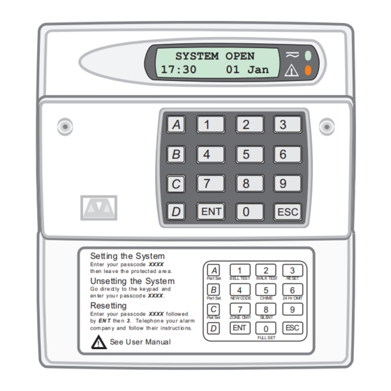
SYSTEM OPEN
17:30
01 Jan
A
1
2
B
4
5
C
7
8
D
ENT
0
Sett ing the Syst em
Ent er your pa ss code XXXX
A
1
th en lea v e th e pro tec t ed a re a.
Part Set
BELL TEST
Unsetting the System
B
Go dir e ct ly to t he ke yp ad and
4
en ter you r p as scod e XXXX .
Part Set
NEW C ODE
Resetting
C
7
Ent er your pa ss code XXXX f ollow ed
Part Set
ZONE O MIT
by EN T the n 3. Te leph on e you r a lar m
D
ENT
com pan y and follow th eir instr uct io ns.
See U ser Manual
!
Manual
_
~
3
6
9
ESC
2
3
WALK TEST
R ESET
5
6
CHIME
24 Hr OMIT
8
9
SILENT
ESC
0
FU LL SET
Advertisement
Chapters
Table of Contents

Related Manuals for Menvier Security TS590


Summary of Contents for Menvier Security TS590
- Page 1 TS590 Intruder Alarm Control Panels SYSTEM OPEN 17:30 01 Jan Sett ing the Syst em Ent er your pa ss code XXXX th en lea v e th e pro tec t ed a re a. Part Set BELL TEST...
-
Page 2: Table Of Contents
TS590 Installation Manual Contents Overview Connecting a Printer ....18 Using the DATAC / RS232 Printer ..18 Introduction . - Page 3 TS590 Installation Manual Custom Text Menu ....41 Circuit Text ......41 Banner Message.
-
Page 4: Introduction
All remote keypads have “Power The TS590 system can monitor 6 zones locally and LED” and a programmable “Function LED” (the up to 14 zones via remote keypads or LECs. All “Function LED”... -
Page 5: System Architecture
Number of Zones = 6 to 14 Figure 1. TS590 System Architecture Specifications Control Panel Output: (NETLCD only) Switched -ve @100mA Part No.: TS590 - 6 to 14 zones Dimensions: 150(W) x 104(H) x 30(D) mm Input Supply : 230V ±10% 50Hz Material: 3mm Polycarbonate Current:... - Page 6 Overview TS590 Installation Manual (This page has been left Intentionally blank.)
-
Page 7: System Installation
A B C D E A B C D E A B C D E A B C D E Control Panel Remote Network Power for Power for Power for Power for detectors detectors detectors detectors Figure 2. TS590 Remote Network Wiring... -
Page 8: Control Panel Installation
Remove the back box, drill and connected to the spade connection on plug the hole. the transformer. Figure 3. TS590 Control Panel Layout... -
Page 9: Control Panel Pcb Layout
Digicom Outputs Programmable @ 100mA (SELV) Auxiliary Tamper (SELV) Extension loudspeaker (SELV) SPEAKER VOLUME External sounder connections LED1 (SELV) Programmable BATT Detection FAULT Circuits 1 - 6 (SELV) 21V A.C. from mains transformer (SELV) Aux 12V Figure 4. TS590 Main PCB... -
Page 10: Connection Terminals & Indicators
TS590 Installation Manual Connection Terminals & Indicators LED2 POWER ON This LED indicates that the system power Connection terminals on the TS590 are described (mains or battery) is healthy. as ether “Safety Extra-Low Voltage” (SELV) circuits or “Telecommunication Network Voltages” (TNV) SYSTEM CURRENT CONSUMPTION circuits. -
Page 11: Mains Connection
A 7Ah battery must be fitted to the system to allow programmable output. it to function during a mains fail condition. The TS590 is equipped with a “Battery Protection” “ Tamper Switch. circuit so that if a battery is accidentally reverse Remote Keypad case tamper connected or its voltage is below 4V, the “BATT... -
Page 12: Installation Procedure
System Installation TS590 Installation Manual plug the wall as required. Pass all the cables into the base via the cable entry points as appropriate and secure the base to the wall. 3. Connect “Remote Network” and detection Display Module LED MIMIC circuit cables to the appropriate terminals. -
Page 13: Keypad Loudspeaker Connections
TS590 Installation Manual System Installation Keypad Loudspeaker Connections A single 16 Ohm loudspeaker may be wired to the keypad if required. This loudspeaker will follow the CABLE ENTRY existing keypad sounder and its volume level can Network connections be adjusted by the speaker volume pot (VR1). -
Page 14: Lec 6
System Installation TS590 Installation Manual ’ TS590 Power LED This LED indicates that mains power is Panel I/D Selector Circuit A Circuit B present at the control panel. When mains Output power is removed and the system is running on its standby battery, this LED will flash. -
Page 15: Lec 6 Installation
TS590 Installation Manual System Installation Wiring Detection Circuits LEC 6 Installation Always ensure that all power (mains and battery) is All detection circuits may be wired as “End Of Line” removed before making any connections to the 6 (EOL) or “Double Pole” (DP). Both methods can be Zone LEC. -
Page 16: End Of Line
System Installation TS590 Installation Manual External Sounder Connections End Of Line The EOL method requires the following: The following terminals have been provided to allow connections to an external sounder: The detector alarm contacts must have a 4K7 shunt resistor fitted. -
Page 17: Extension Loudspeakers
TS590 Installation Manual System Installation Extension Loudspeakers REM RESET If the system is programmed for “Engineer Reset”, Up to two extension loudspeakers can be then after a full alarm the system will require connected across the [SPK+] and [H/O-] terminals resetting, normally this is done by the engineer or on the control panel PCB. -
Page 18: Dc54 & Dc58M Installation
) Figure 17. DC54/DC58 Connections Connecting a Printer The TS590 supports two type of printers, the CPA6 printer (no longer available) and any standard RS232 printer. When using an RS232 printer a DCI/MPA printer adaptor will be required. Menvier... -
Page 19: Pre Power-Up Checks
TS590 Installation Manual System Installation Pre Power-Up Checks Power-Up Checks Once the system is installed, but prior to When the initial power-up checks have been powering-up, give the system one final check to completed, check the following: ensure that: 1. Switch off the 240V mains supply and measure 1. -
Page 20: Nvm Defaults
System Installation TS590 Installation Manual NVM Defaults Section Option Default Section Option Default User 00 Engineer 1234 Full Set Final Exit Setting User Codes User 01 Master 5678 Part Set A Timed Exit Setting Modes Key p ad Keypad Outputs 1, 2,... -
Page 21: Engineer's Menu 1
TS590 Installation Manual Engineer’s Menu 1 Engineer’s Menu 1 Introduction Engineers menu 1 is the first of two engineers Enter Engineer's menus, which is selected when the engineer’s Passcode passcode is entered. The engineer may leave 1 2 3 4 “Engineer menu 1"... -
Page 22: Keypad Outputs
Engineer’s Menu 1 TS590 Installation Manual Keypad Outputs [1.1] Digicom Channels [1.3] Outputs 1-4 can be programmed to any of the The 8 plug-on digicom channels can be output types shown on pages 22 to 24. programmed to any of the output types shown on pages 22 to 24. - Page 23 TS590 Installation Manual Engineer’s Menu 1 Type/Description Type/Description 004 Walk Test 017 Part Set B Selected Activates when the "Walk Test" option is Activates when "Part Set B" is selected. selected and deactivates when the "Walk Test" Deactivates when the system is unset.
- Page 24 Engineer’s Menu 1 TS590 Installation Manual Type/Description Type/Description 032 Duress Alarm 044 General Fault Activates when a duress passcode is entered Activates during battery fault or when the and deactivates when the duress alarm is system is prevented from being set.
-
Page 25: Program Circuits
[1.4] 8 Exit Terminator A circuit that is normally connected to a push The TS590 can monitor up to 14 detection circuits. button outside the protected premises, which Each circuit must be programmed in order for the can be used to finally set the system or area. - Page 26 Engineer’s Menu 1 TS590 Installation Manual part-set condition. The “Entry” attribute can 2 Double Knock Circuits programmed with this attribute will only only be assigned to Night, 24hr and Final Exit cause an alarm condition if: circuit types. When assigned to a 24 Hour...
-
Page 27: System Timers
TS590 Installation Manual Engineer’s Menu 1 count down. If a valid user passcode has not System Timers [1.5] been entered when the timer reaches zero, The system timers are as follows: the internal sounders are activated and the 00 Abort Delay “2nd Entry”... - Page 28 Engineer’s Menu 1 TS590 Installation Manual then all circuits will report 3 activation’s before 12 Monitor Dur. This timer affects the duration of the “Timed they are locked out from sending any more. Output” (No. 042). This timer has a working Note: this does not affect the re-arm of the range of 000-199 minutes.
-
Page 29: Setting Modes
TS590 Installation Manual Engineer’s Menu 1 014 the test call will be signalled at 14.00 (2.00pm). This timer has a working range of 000 Engineers menu 1 Select Options :- - 023. (Default: 003) Setting Mode ? Enter Group > -... -
Page 30: Remote Reset Algorithm
Engineer’s Menu 1 TS590 Installation Manual Remote Reset Algorithm [1.8] Configuration [1.9] When the system is programmed for “Engineer The configuration options are as follows: Reset” the requirement to send an engineer to site 00 Bell is an SAB can be overridden by the user by using the When programmed as “Yes”... - Page 31 TS590 Installation Manual Engineer’s Menu 1 08 Extended format 16 SET with AC off When programmed as “Yes" the plug-on When programmed as “Yes”, the system can digicom will report using Point ID extended b e s et wit hou t m ain s p ower . Whe n format.
- Page 32 In some cases these codes do after an unconfirmed alarm. (Default = No) not conform to Cooper Security Ltd’s implementation of the CID standard. This 32 Confirmation After Entry option allows you to program the control unit to When programmed as “Yes”...
- Page 33 TS590 Installation Manual Engineer’s Menu 1 36 Entry Confirmation After 2 circuits When programmed as “Yes” the control unit Engineers menu 1 sends a confirmed alarm if an intruder Select Options :- activates two separate zones after the entry timer expires. If the control unit is in alarm...
-
Page 34: Go To User Menu 1
Engineer’s Menu 1 TS590 Installation Manual Go to User Menu 1 [1.0] View Location Text [1.B] This option allows the engineer to access “User This option allows the engineer to view the panel menu 1", the flowchart below shows the options location text. -
Page 35: Engineer's Menu 2
TS590 Installation Manual Engineer's Menu 2 Engineer's Menu 2 Introduction Engineers menu 1 Engineer's menu 2 is selected by pressing the [ENT] Select Option :- key whilst Engineer's menu 1 is selected. Each menu option can be selected by pressing the relevant “Hot key”. -
Page 36: View Circuits
Engineer's Menu 2 TS590 Installation Manual View Circuits [2.1] Set System Time [2.2] Each detection circuit may be viewed to The system time is displayed in a 24hr format on all ascertain its status. The circuit status conditions remote keypads and is also used to time stamp and resistance are shown below: events in the system event log. -
Page 37: Change Passcode
TS590 Installation Manual Engineer's Menu 2 Change Passcode [2.4] Alter Shunt Group [2.6] This option allows the engineer to change their Circuits can be assigned to the shunt group. The passcode. The default passcode is 1234 but the shunt group can be isolated by using user menu 1 installation engineer should change this to their option 6 or by using a “Shunt”... -
Page 38: Configure Part Sets
[2.8] View System Log [2.9] The TS590 can be configured to have up to three The engineer can use this option to view the parts set modes (Part Set A, Part Set B and Part Set system log. The [A] and [C] keys allow you to scroll C). -
Page 39: Log Event Codes
TS590 Installation Manual Engineer's Menu 2 Log Event Codes Description AC OFF Mains power removed. AC RESTORED Mains power restored ACTION ALARM Alarm activated when system is part-set. ALARM 01-14 Full alarm from circuit (01-14). AUX/BELL TAMPER Auxiliary tamper activated. -
Page 40: Log Event Codes
Engineer's Menu 2 TS590 Installation Manual Log Event Codes Description PANEL LID TAMPER Control panel lid removed. PART SET A/B/C System Part-Set using one of the A, B, or C buttons. PASSCODE 00-15 User passcode entered. (00-15). REINSTATEMENT Time and date for reinstatement. -
Page 41: Custom Text Menu
TS590 Installation Manual Engineer's Menu 2 LCD Only Engineers menu 2 Engineers menu 2 Select Option :- Select Option :- 1-CCT, 2-Banner Call back No. Call Number 1 3-Location Tel No. 0181 12345678 = Circuit Text = Call No. 1 = Banner Message = Call No. -
Page 42: Modem Password
Engineer's Menu 2 TS590 Installation Manual Modem Site No. LCD Only This option allows the Modem site number to be Engineers menu 2 Select Option :- programmed. The “Modem Site No.” is a 4 digit number that is used as a site reference. When using the “Lineload”... -
Page 43: Digicom Tests
TS590 Installation Manual Engineer's Menu 2 Digicom Tests Text Editing Keys This option allows the engineer to test each When programming any text the keys on the channel on the plug-on digi-modem (DC6) and keypad function as shown below: the five digi outputs on the main PCB. - Page 44 Engineer's Menu 2 TS590 Installation Manual (This page has been left intentionally blank.)
-
Page 45: Appendices
TS590 Installation Manual Appendices Appendices Point ID Extended Reporting Point ID extended reporting is a new format which Code Description when used with the DC58M can be used to report Engineer program mode selected circuit ID data, user ID etc. The central station... - Page 46 Appendices TS590 Installation Manual Kitchen Dining Room Hall Garage Lounge Key: Passive Infra-Red Detector Bathroom Magnetic Contact Bedroom 2 Remote Keypad Control Panel Landing Bedroom 1 Bedroom 3 Figure 19. A Typical 3 Bedroom House...
-
Page 47: Part-Set Application Example
Part-Set Application Example Alarm Abort & Confirmation This application example shows how to configure The TS590 supports “Alarm Abort” and “Sequential the part set buttons to set different areas of a 3 Confirmation”. The alarm abort can be achieved bedroom house. -
Page 48: Setup New Users
Setup New Users company or by making the first two digits of The TS590 allows up to 15 users to operate the the passcode the same. alarm system, each user is assigned a user type and 4 digit passcode. -
Page 49: Quick Reference Engineers Menus
TS590 Installation Manual Appendices Quick Reference Engineers Menus Engineers Menu 1 Options Page Options Page System Configuration Program Keypad Outputs 1 = Kepad Output 1 00 = Bell is an SAB Bell is an SCB 2 = Kepad Output 2... -
Page 50: Engineers Menu 2
Appendices TS590 Installation Manual Quick Reference Engineers Menus Engineers Menu 2 Output Types Output Type Output Type Options Page 000 Bell On 031 Exit View Circuits 001 Strobe On 032 Duress Alarm A = Scroll Next Circuit C = Scroll Previous Circuit... -
Page 51: Quick Reference User Menus
TS590 Installation Manual Appendices Quick Reference User Menus User Menu 1 User Menu 2 Options Options Bell Test View Circuits A = Scroll Next Circuit Walk Test C = Scroll Previous Circuit Remote Reset Set System Time Enter Reply code + ENT Enter time e.g. - Page 52 Appendices TS590 Installation Manual Cooper Security Ltd, Security House, Vantage Point Business Village, Mitcheldean, Gloucestershire, GL17 0SZ. England Product Support Tel: +44 (0)1594 545556 Available between; 08:15 and 17:00, Monday to Thursday. 08:15 and 12:45 Friday. Emergency service only between 12:45 and 17:00 Friday.
Need help?
Do you have a question about the TS590 and is the answer not in the manual?
Questions and answers
Code Tamper 01 - how can this be resolved?
The "Code Tamper 01" issue on the Menvier Security TS590 indicates a tamper event related to the keypad. To resolve this issue, follow these steps:
1. Verify the keypad for any physical tampering or unauthorized access.
2. Check if the correct passcode is being used.
3. If the master user (User 01) has forgotten their passcode, the installation engineer can reset it to the default code "5678" using the engineer's menu.
4. Log in as an engineer and navigate to the reset user code option.
5. Press "ENT" to reset User 01’s passcode.
6. Confirm that the reset operation is logged.
7. Test the system to ensure normal functionality.
This process should clear the "Code Tamper 01" issue and restore normal operation.
This answer is automatically generated