
Related Manuals for Menvier Security TS510


Summary of Contents for Menvier Security TS510
-
Page 1: Installation Manual
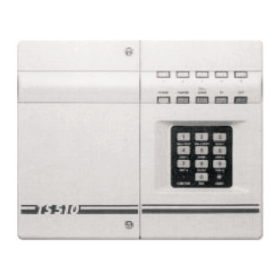
TS510 INTRUDER ALARM CONTROL PANEL INSTALLATION MANUAL Menvier Security Ltd., Hither Green, Clevedon, Avon BS21 6XU Tel: 0275 870078, Fax: 0275 343453, Tlx: 44782... -
Page 2: Table Of Contents
All rights reserved. No part of the information contained in this document may be reproduced or copied by any means without the written permission of Menvier Security. Pt No B.18783 Drg No 33:0919:00.Iss 04.Doc 01 © Menvier Security Ltd. 1993... -
Page 3: Specification
It is therefore very important to read the manual thoroughly before starting any work. This is particularly significant if it is your first TS510 installation. If you have installed a TS510 before then you may wish to turn straight to the Quick Reference Guide (Page 8) to refresh your memory. -
Page 4: Pre-Installation Panel Test
PRE-INSTALLATION PANEL TEST (OPTIONAL) Unpack the TS510, remove the two screws from the front of the panel and lift away the left hand cover. Disconnect the transformer leads, release the clip near the top of the PCB and then carefully remove the complete right hand cover assembly. -
Page 5: System Wiring
SYSTEM WIRING All ZONE and TAMPER inputs are linked out prior to despatch from the factory. Remove these links from those zones which are to be used, but leave the links in unused zones. The EXIT TERMINATOR link MUST BE REMOVED even if this facility is not used, otherwise all programmed information will be lost on total power loss (mains and battery). - Page 6 AC IN: These are connected to the mains transformer via the two AC leads, (their polarity is not critical). AUX +/-: These provide auxiliary power for PIRs and other devices within the protected area. The system current consumption can be determined by measuring the voltage across the two test pads located between the terminal blocks for circuit 1 and circuit 2.
- Page 7 SYSTEM WIRING (Cont.) FINAL EXIT - The KEY SW/F.EXIT input can be alternatively used as a Final Exit zone, if so programmed, thus providing a sixth zone. The KEY SW/F.EXIT input uses a single conventional wiring loop, and the tamper protection is provided by the Aux Tamper loop, (see Fig 2). P./A.
-
Page 8: Remote Keypad
REMOTE KEYPAD The option of up to 4 remote keypads (order code: TS510.REM) are supplied with an interface which plugs onto the main panel PCB. The connections from the panel to the Remote Keypad require a five core cable (max length 50m). - Page 9 Fit the DC3 connector to the TS510 plug as shown. Fig 3 - DC3 and TS510.REM Connections Fit the TS510.IF to the panel plug taking care to ensure that correct alignment is made and that no pins are visible. Fig 4 - TS510.IF and TS510.REM Connection...
-
Page 10: Quick Reference Guide
QUICK REFERENCE GUIDE FS1 (AUX 12V) FUSE = 1A FS2 (BELL 12V) FUSE = 1A MAINS FUSE = 160mA OPTIONS 1 Bell duration (20 mins) Bell delay time (0 mins) Signalling options ZONE LED On for: Bell= SAB No Abort Audible PA PA audible on L.F. -
Page 11: Programming
PROGRAMMING The TS510 is very easy to program, using a combination of simple keystrokes, lights and sounds. Additionally, there are two ways to speed up the process even further; 1) fill in the programming record before you start, and 2) use the Default Settings where they coincide with your own requirements. - Page 12 TS510 PROGRAMMING GUIDE AND SYSTEM RECORDS COMPLETE FORM USING BOXES PROVIDED AND LEAVE WITH THE CONTROL PANEL FOR FUTURE REFERENCE ENTER ENGINEER CODE AND THE [CALL ENGR] LED WILL ILLUMINATE TOGETHER WITH THAT OF THE ZONE WHICH CREATED THE LAST ALARM. IF THE [CALL ENGR] LED FLASHES, THE LAST ALARM OCCURRED WITH A LINE FAULT PRESENT.
- Page 13 BELL DURATION: Press [6] [1] and 3 zone LEDs will light, indicating that a 3 digit bell duration time (in mins) is required. Once complete, the confirmation tone will be heard. eg. for 20 mins, enter 020 BELL DUR. DEFAULT = 020 MINS BELL DELAY: Press [6] [2] and 3 zone LEDs will light, indicating that a 3 digit bell delay time (in mins) is required.
- Page 14 KEYSWITCH/FINAL EXIT: Press [6] [7] and of the following LEDs will light, showing how the keyswitch input will operate. FULL SET PARTSET A PARTSET B FINAL EXIT NOT USED FOR: ON / OFF ON / OFF ON / OFF ON / OFF NOT USED VIEW EVENT LOG: Pressing [6] [8] will allow the event log to be viewed.
Need help?
Do you have a question about the TS510 and is the answer not in the manual?
Questions and answers