Xerox Phaser 3600 Service Manual
Hide thumbs
Also See for Phaser 3600:
- User manual (109 pages) ,
- Instruction (23 pages) ,
- Voluntary product accessibility template (11 pages)
Table of Contents
Advertisement
Quick Links
Advertisement
Table of Contents
Troubleshooting

Related Manuals for Xerox Phaser 3600


Summary of Contents for Xerox Phaser 3600
- Page 1 Service Manual 701P47822 Phaser 3600 ® Laser Printer...
-
Page 3: Service Manual
Service Manual 701P47882 ® Phaser 3600 Printer Warning The following servicing instructions are for use by qualified service personnel only. To avoid personal injury, do not perform any servicing other than that contained in the operating instructions, unless you are qualified to do so. First Printing: September 2008... - Page 4 Xerox technical training materials and service manuals are intended for use by authorized Xerox service technicians and service partners only and are not for resale. These materials may not be distributed, copied, or otherwise reproduced without prior written consent from Xerox Corporation.
-
Page 5: Service Terms
Product Terms Caution: A personal injury hazard exists that may not be apparent. For example, a panel may cover the hazardous area. Danger: A personal injury hazard exists in the area where you see the sign. Phaser 3600 Printer Service Manual... -
Page 6: Symbols Marked On The Product
Refer to the manual(s) for information. Do not touch the OPC Drum. Do not expose the item to sunlight. Do not tilt the Print Cartridge. 35°C Do not expose item to extreme temperature. 0°C 95°F 32°F Recycle the item. Phaser 3600 Printer Service Manual... -
Page 7: Power Safety Precautions
Phaser 3600 Printer Service Manual... -
Page 8: Electrostatic Discharge Precautions
Handle IC’s and Erasable Programmable Read-Only Memories (EPROM’s) carefully to avoid bending pins. Pay attention to the direction of parts when mounting or inserting them on Printed Circuit Boards (PCB’s). Phaser 3600 Printer Service Manual... -
Page 9: Service Safety Summary
Class 1 Laser Product The Phaser 3600 is certified to comply with Laser Product Performance Standards set by the U.S. Department of Health and Human Services as a Class 1 Laser Product. This means that this product does not emit hazardous laser radiation;... -
Page 10: Servicing Electrical Components
This printer uses heat to fuse the toner image to paper. The Fuser is VERY HOT. Turn the printer power Off and wait at least 5 minutes for the Fuser to cool before attempting to service the Fuser or adjacent components. viii Phaser 3600 Printer Service Manual... -
Page 11: Regulatory Information
Consult the dealer or an experienced radio/television technician for help. Any changes or modifications not expressly approved by Xerox could void the user's authority to operate the equipment. To ensure compliance with Part 15 of the FCC rules, use shielded interface cables. -
Page 12: European Union
European Union The CE mark applied to this product symbolizes Xerox’s declaration of conformity with the following applicable Directives of the European Union as of the dates indicated: December 12, 2006: Council Directive 2006/95/EC as amended. Approximation of the laws of the member states related to low voltage equipment. -
Page 13: Manual Organization
Manual Organization The Phaser 3600 Printer Service Manual is the primary document used for repairing, maintaining, and troubleshooting the printer. Use this manual as your primary resource for understanding the operational characteristics of the printer and all available options. This manual describes specifications, theory, and the diagnosis and repair of problems occurring in the print engine and attached options. - Page 14 Phaser 3600 Printer Service Manual...
-
Page 15: Table Of Contents
Phaser 3600 Operational Overview ........ - Page 16 Jam At Duplex (Duplex Jam 2) ............3-17 Check Cartridge, Invalid Print Cartridge, Non-Xerox Cartridge, Replace Print Cartridge ....3-18 Close Fuser Door .
- Page 17 Tray 1 (MPT) Solenoid (PL 1.1.26) ............7-29 Phaser 3600 Color Laser Printer Service Manual...
- Page 18 PL 2.3 Duplex Assembly ..............8-30 Phaser 3600 Printer Service Manual...
- Page 19 Acronyms and Abbreviations ..............A-2 Index Phaser 3600 Color Laser Printer Service Manual...
- Page 20 Phaser 3600 Printer Service Manual...
-
Page 21: General Information
General Information In this chapter... Printer Configurations Consumable and Service Part Life Expectancy Parts of the Printer Control Panel Printer Specifications Media and Tray Specifications Chapter... -
Page 22: Printer Configurations
500-Sheet Feeder 097S03385 Cartridges Standard-Capacity Print Cartridge 106R01370 (7,000 pages) High-Capacity Print Cartridge (14,000 106R01371 pages) Extra High-Capacity Print Cartridge 106R01372 (20,000 pages) Metered/Pagepack Print cartridge 106R01369 (20,000 pages) Gear Lubricant Xerox lubricant Plastislip grease 043E00550 Phaser 3600 Printer Service Manual... -
Page 23: Consumable And Service Part Life Expectancy
Feed Roller Kit 150,000 pages Retard Roller 150,000 pages Separator Pad 150,000 pages Note The service parts are not tracked with an NVRAM counter and there is no replace or low warnings associated with these service parts. Phaser 3600 Printer Service Manual... -
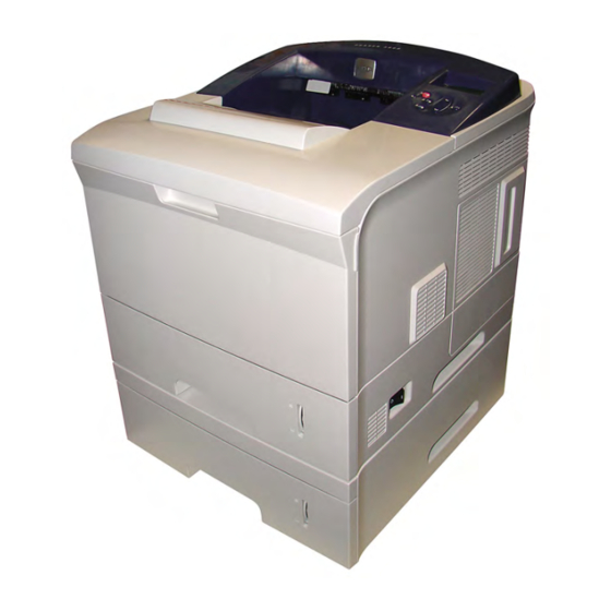
Page 24: Parts Of The Printer
Tray 1 (MPT) Release Tray 2 On/Off Switch Paper Gauge s3600-001 Rear View Rear Door Network Port (optional for 3500B) Duplex Unit (optional) USB Port IEEE 1284 Parallel Port Tray 3 Optional Cable Connector Power Cord Receptacle s3600-112 Phaser 3600 Printer Service Manual... -
Page 25: Control Panel
Error and Warning Messages When there is a problem with the printer, the Control Panel LED (3) blinks red for an error and a warning. An error or warning message is displayed in the Alphanumeric Display (5). Phaser 3600 Printer Service Manual... -
Page 26: Printer Specifications
Place the printer on a level, solid surface with adequate strength for the weight of the printer. 596 mm 1255.6 mm (24.6 in.) (49.2 in.) 100 mm (4 in.) 320 mm (12.6 in.) 100 mm (4 in.) 482.6 mm (18.8 in.) s3600-003 Phaser 3600 Printer Service Manual... -
Page 27: Printer Physical Specifications
Continuous Operating Printing Letter: Speed (ppm = pages per Up to 40 ppm minute) Up to 38 ppm First Print-Out 10 seconds or less (in seconds) Warm-Up Time Power-on Boot: 40 seconds or less Phaser 3600 Printer Service Manual... - Page 28 Optional Tray 3 < 2.0 mm (0.08 ) Simplex & Horizontal < 2.5 mm (0.1 ) Duplex & Horizontal < 2.5 mm (0.10 ) Simplex & Vertical < 3.0 mm (0.12 ) Duplex & Vertical Phaser 3600 Printer Service Manual...
-
Page 29: Electrical Specifications
Less than 56.0 dBA Simplex from SCF Less than 59.0 dBA Duplex from Tray1 Less than 59.0 dBA Measurement Standby Less than 35.0 dBA Warm up Less than 50.0 dBA Maximum Less than 60.0 dBA Phaser 3600 Printer Service Manual... -
Page 30: Media And Tray Specifications
Sensing Paper Empty Sensor Standard Capacity 500 sheets Cassette Tray Media sizes A4/A5/Letter/Legal/Executive/Folio/ Oficio/ISO B5/JIS B5 Media types Plain paper Media weight 16~28lb (60 to 105g) Sensing Paper Empty Sensor and Paper Size Sensor 1-10 Phaser 3600 Printer Service Manual... - Page 31 (FPOT) from sleep/power save mode Less than 40 sec from cold status Less than 49 sec Warm Up Time from sleep/power save mode Less than 31 sec from cold status Less than 40 sec Phaser 3600 Printer Service Manual 1-11...
- Page 32 General Information Media Print Speed Toner save setting unit Support Support (30%) LUI(Local UI) Support(UI2.0) Duplex Print Simplex Support Manual Duplex Duplex Optional 1-12 Phaser 3600 Printer Service Manual...
-
Page 33: Theory Of Operation
Theory of Operation In this chapter... Phaser 3600 Operational Overview Printer Paper Path Printer Controls Sensor Functions Printer Controls Chapter... -
Page 34: Phaser 3600 Operational Overview
Phaser 3600 Operational Overview Summary of the Printing Process The Phaser 3600 Laser Printer is a desktop monochrome laser printer, applying the principals of an electrophotographic system to place a monochrome image onto the print media. The system contains a drum and developing unit which places the toner image onto print media producing monochrome prints through the transfer unit. -
Page 35: Print Cartridge And Print Modes
Transfer Roller s3600-004 Print Modes The Phaser 3600 Laser Printer provides two print modes: Draft mode: Uses a combination of reduced toner output and the lowest resolution (300 x 300 dpi) to extend print cartridge life. Enhanced mode: Used for printing on plain paper with an addressable resolution of 1200 x 1200 dpi. -
Page 36: Printer Paper Path
Paper will exit the printer to the face down top tray. A door at the rear of the printer provides access for jam clearance. All major components of the printer are explained in greater detail under Printer Controls on page 2-10. Phaser 3600 Printer Service Manual... -
Page 37: Duplex Paper Path
2-sided printing. When the main motor turns, all the paper path components also turn except the Pick-Up Roller. The Pick-Up Roller assembly moves the paper along the path with the Feed Solenoid. There is a separate Developer Motor for the Print Cartridge. Phaser 3600 Printer Service Manual... -
Page 38: Print Engine Assemblies
LVPS (CN19) Ethernet (CN1) Power (CN22) USB (CN2) Duplex (CN17) Main Motor Parallel Port (CN18) (CN3) Exit Sensor (CN23) Joint Board (CN24) Optional 3rd Tray (CN25) RAM DIMM 1 (CN14) RAM DIMM 0 (CN12) s3600-077 Phaser 3600 Printer Service Manual... -
Page 39: Laser Scan Unit (Lsu)
In the front side of the tray, there is a paper level indicator. Paper Pick-up Process Functions include a paper pickup function, paper feeding function, and the removal of electronic static. Phaser 3600 Printer Service Manual... -
Page 40: Transfer Roller Assembly
Thermistor: Monitors the surface temperature of the Heat Roller. This information is used to control the heat lamp and thus keep the Heat Roller at the correct temperature. Thermostat: Prevents overheat damage when unexpected system faults occur. Phaser 3600 Printer Service Manual... -
Page 41: Duplex And Tray Assemblies
Feeding Method : Cassette Type Feeding Standard : Center Loading Feeding Capacity : Cassette 500 Sheets(75g/ , 20lb Paper Standard) Paper Detecting Sensor : Photo Sensor Paper Size Sensor : Yes Phaser 3600 Printer Service Manual... -
Page 42: Printer Controls
The default paper pick selection at power ON is Tray 2, Auto-Select ON is also default. If the default tray is empty, the printer will automatically switch to any other tray that contains paper unless Auto-Select is set to OFF. 2-10 Phaser 3600 Printer Service Manual... -
Page 43: Laser Scan Unit (Lsu) Control
Interconnect Board and the associated signals are supplied to the Main Board. The CRUM not only detects cartridge presence, it also determines whether it is a genuine Xerox cartridge. When the toner remaining falls to 15%, the printer displays a low toner message on the Control Panel display. -
Page 44: Fuser Temperature Control
From 3 consecutive pages: Lower than 25 degrees C than the fixed fusing temperature over 7 seconds. Over Heat Error Temperature is higher than 230 degrees Engine Over Heat C over 10 seconds. Error 2-12 Phaser 3600 Printer Service Manual... -
Page 45: Sensor Functions
When the sensing area is vacant, nothing is between the arms of the sensor, light falls on the photo-receptor sending the signal High. If the light is interrupted, the photo-transistor goes Low. Actuator s3600-133 Phaser 3600 Printer Service Manual 2-13... - Page 46 Microswitches also employ hooks or catches for retention in the bracket or frame. Actuator Button Blade Contact s3600-134 Thermistors Thermistors have a known value of resistance whose value varies with temperature. Used primarily in the Fuser for temperature sensing. 2-14 Phaser 3600 Printer Service Manual...
-
Page 47: Sensors In The Paper Path
If the paper takes too long getting to the sensor, or it stays at the sensor location too long, the Main Board will shut down the machine, the control panel LED will blink red, and a “Jam” error message will display on the control panel. Phaser 3600 Printer Service Manual 2-15... - Page 48 Duplex Unit. As the paper leaves the Duplex Unit, it activates the Duplex Sensor within the unit. This activates the Feed Roller to position the paper for printing on the second side of the paper. 2-16 Phaser 3600 Printer Service Manual...
-
Page 49: Power Supplies
The power distribution section receives AC voltage and creates the required DC outputs (3.3 VDC, 5 VDC, and 24 VDC) to power the printer components. It also supplies AC voltage to the Fuser Assembly. CON03 CON01 CON02 CON06 CON04 CON05 s3600-078 Phaser 3600 Printer Service Manual 2-17... -
Page 50: Switching Mode Power Supply (Smps)
Main Board. The SMPS also drives the AC heater unit, which supplies controlled current levels to the Fuser assembly as an independent module. FUSER DEVE SUPPLY s3600-079 2-18 Phaser 3600 Printer Service Manual... -
Page 51: Error Messages
Error Messages In this chapter... Troubleshooting Overview Service Diagnostics Service Diagnostics Menu Map Troubleshooting Error Messages Chapter... -
Page 52: Troubleshooting Overview
Error Messages Troubleshooting Overview This section covers troubleshooting procedures for the Phaser 3600 Laser Printer. When an error first occurs, record the error message and code and then cycle power to the printer to see if the error recurs. To troubleshoot image-quality problems, see “Image-Quality Troubleshooting”... -
Page 53: Service Diagnostics
Turn the printer power OFF. While holding down the ‘OK’ button (1), turn the printer back ON (2). Note Refer to the “Diagnostic Test Menu Map” on page 3-5 to see the description of all component tests. Phaser 3600 Printer Service Manual... -
Page 54: Service Diagnostic Control Panel Button Descriptions
Scrolls up one menu item within a menu list. This control DOWN does not ‘wrap’. Used to increment values in tests requiring user input. Enters the highlighted menu. Executes the current test item. Used to select the value entered by the user. Phaser 3600 Printer Service Manual... -
Page 55: Diagnostic Test Menu Map
If the Tray is opened, "Open" Tray 3 Cassette Cassette message will be displayed and if not, "Closed" displayed Fuser Door If the Door is opened, "Open" Fuser Door message will be displayed and if [Closed] [Open] not, "Closed" displayed. Phaser 3600 Printer Service Manual... - Page 56 [With Paper] after touching the sensor. DJam 1 The first value lists normal display DJam1 Sensor Sensor before touching the sensor, and the [Without Paper] second value lists normal display [With Paper] after touching the sensor. Phaser 3600 Printer Service Manual...
- Page 57 The first value lists normal display T2 PSize1 T2 Psize1 Sen Sensor before touching the sensor, and the [Low] [High] second value lists normal display after touching the sensor. Phaser 3600 Printer Service Manual...
- Page 58 [On] [Off] Duplex Mtr The motor will run on the forward Duplex Mtr Fwd direction. [On] [Off] T2 Feed The motor will run on the forward T2 Feed Motor Motor direction or stop. [On] [Off] Phaser 3600 Printer Service Manual...
- Page 59 160 degrees. Fuser Temp The Control Panel displays a digital Fuser Temp equivalent [xxx] of the analog value. [xxx] Inner Temp The Control Panel displays a digital Inner Temp equivalent [xxx] of the analog value. [xxx] Phaser 3600 Printer Service Manual...
- Page 60 Pattern Print The printer prints a pattern test page Print Test Print into Tray (MPT). [On] [Off] (Test 8) T2 Version Displays Tray 2 version 2.00 T3 Version Displays Tray 3 version 1.00 T4 Version DPX Version 1.03 3-10 Phaser 3600 Printer Service Manual...
-
Page 61: Troubleshooting Error Messages
Error Messages Troubleshooting Error Messages The following list summarizes the Phaser 3600 error messages: Jam At Tray [1|2|3] (JAM 0) The leading edge of the paper doesn’t pass the Feed Sensor, or the sensor does not turn ON. After paper pick, paper is not fed. - Page 62 Error Messages Check Cartridge, Invalid Print Cartridge, Non-Xerox Cartridge This message appears when: A print cartridge is not detected. A non-Xerox print cartridge is installed. The Toner Sensor Board is malfunctioning. Close Top Cover. This message appears when the: Top cover is damaged Sensor or actuator is damaged.
- Page 63 (page 7-21). Use service diagnostics to check Replace the Main Replace the the operation of the tray solenoid. Board (page 7-39). inoperative Do the tray solenoids operate solenoid correctly? (page 7-29). Phaser 3600 Printer Service Manual 3-13...
- Page 64 Go to Step 4. Replace the Exit the Exit Sensor. Sensor page 7-56 Does the sensor operate correctly? Replace the Fuser Assembly Complete. Replace the SMPS (page 7-54) and retest. (page 7-76). Did this correct the problem? 3-14 Phaser 3600 Printer Service Manual...
- Page 65 Do the Fuser gears rotates when Assembly the Main motor is on? (page 7-54). Use the embedded diagnostics to Replace Main Replace the SMPS check the Exit Roller. Board (page 7-39). (page 7-76). Are the rollers operational? Phaser 3600 Printer Service Manual 3-15...
- Page 66 Are the rollers damaged or Replace the Duplex Go to Step 7. binding? Roller (page 7-47). Is there damage to the duplex Replace the Duplex Replace Main Board assembly. Unit (page 7-37). (page 7-39). 3-16 Phaser 3600 Printer Service Manual...
-
Page 67: Jam At Duplex (Duplex Jam 2)
Rollers for any signs of damage Roller (page 7-47). or binding. Replace the Duplex Unit. Replace the Main Replace the HVPS Does the problem still occur? Board (page 7-39). Power Supply Board (page 7-75). Phaser 3600 Printer Service Manual 3-17... -
Page 68: Check Cartridge, Invalid Print Cartridge, Non-Xerox Cartridge, Replace Print Cartridge
Error Messages Check Cartridge, Invalid Print Cartridge, Non-Xerox Cartridge, Replace Print Cartridge Troubleshooting Reference Table Applicable Parts Wiring and Plug/Jack Map References Print Cartridge, PL1.1.34 “Map 2- Main Board” on page 9-5 Toner Sensor Board, PL1.3.47.2 “Main Drive/Joint Board and Optional Tray Wiring Diagram”... -
Page 69: Close Fuser Door
Is the Top Cover or actuator damaged? Use diagnostics to test the Cover Replace the Main Replace the Open Board. Board Cover Open Does the Cover Open board function (page 7-39). Board properly? (page 7-74). Phaser 3600 Printer Service Manual 3-19... -
Page 70: Fuser Failure, Engine Fuser Low Heat Error, Or Engine Fuser Over Heat Error
Replace the Fuser Go to Step 4. thermostats. (page 7-54). Are they open? Is the Fuser getting power? Replace the Fuser Replace the SMPS (page 7-54). (page 7-76). Replace the Main Board (page 7-39). 3-20 Phaser 3600 Printer Service Manual... -
Page 71: Laser Failure
Unit for damage. Did this correct the problem? Use diagnostics to check the laser Replace the Laser Replace the Main motor function. Scan Unit Board Is the Laser Scan Unit Operational? (page 7-70). (page 7-39). Phaser 3600 Printer Service Manual 3-21... -
Page 72: Output Tray Is Full
Is the actuator damaged? (page 7-45). Use diagnostics to test the Tray Full Replace the Main Replace the Tray Sensor. Board Full Sensor Does the sensor operate correctly? (page 7-39). (page 7-23). 3-22 Phaser 3600 Printer Service Manual... -
Page 73: General Troubleshooting
General Troubleshooting In this chapter... Servicing Instructions Preventive Maintenance Procedure Control Panel Troubleshooting Power Supply Troubleshooting Chapter... -
Page 74: Servicing Instructions
2. Use the Repair and Adjustments Procedures to replace the part. Step 5: Final Checkout 1. Test the printer to be sure you have corrected the initial problem and there are no additional problems present. Phaser 3600 Printer Service Manual... -
Page 75: Preventive Maintenance Procedure
The frequency of use and the type of paper a customer prints on determines how critical and how often cleaning the machine is necessary. Record the number of sheets printed. Recommended Tools Toner vacuum cleaner Clean water Clean, dry, lint-free cloth Black light protective bag Phaser 3600 Printer Service Manual... -
Page 76: Control Panel Troubleshooting
Replace the Main Board. Replace the Control Panel. Control Panel LED is On, Control Panel Display Is Blank Remove and reseat the Control Panel wiring to the Main Board. Replace the Control Panel. Replace the Main Board. Phaser 3600 Printer Service Manual... -
Page 77: Power Supply Troubleshooting
Unless otherwise specified, the following voltage tolerances are used within this section. Stated Measured +3.3 VDC +3.135 to +3.465 VDC +5.0 VDC +4.75 to +5.25 VDC +24.0 VDC +21.6 to +26.4 VDC 0.0 VDC Less than +0.5 VDC Phaser 3600 Printer Service Manual... - Page 78 General Troubleshooting Phaser 3600 Printer Service Manual...
-
Page 79: Print-Quality Troubleshooting
Print-Quality Troubleshooting In this chapter... Print-Quality Problems Overview Repeating Defects Control Panel (Internal) Test Print Image-Quality Troubleshooting Chapter... -
Page 80: Print-Quality Problems Overview
See the approved media list, “Media and Tray Specifications” on page 1-10, for media that has been tested and approved for use with the Phaser 3600 Laser Printer. Print a test page to see if the image-quality problem still exists. See Test 8 in the “Diagnostic Test Menu Map”... -
Page 81: Repeating Defects
Banding in Process Direction Uneven Density Voids Repeating Defects Transfer Roller Toner on the back side of the printed page (simplex mode) Light Prints Repeating Defects Spots on Image Fuser Hot or Cold Offsetting Repeating Defects Voids Phaser 3600 Printer Service Manual... -
Page 82: Repeating Defects Measurement Table
Discard the first two prints and retain the remaining prints for image- quality analysis. Deletions Inspect the test print for the presence of deletions or unprinted spots. If these are found, see “Repeating Bands, Lines, Marks, or Spots” on page 5-22. Phaser 3600 Printer Service Manual... - Page 83 Characters in the text paragraphs should be uniform and equal in density. The halftone patches should be uniform in appearance. If the image does not meet the criteria, see “Light or Undertone Print” on page 5-11 or “Background Contamination” on page 5-15. Phaser 3600 Printer Service Manual...
- Page 84 ±2.0 mm of the target crosshairs (each line on the target is 1.0 mm). If the image does not meet the criteria, see “Skew” on page 5-25. Phaser 3600 Printer Service Manual...
- Page 85 Print-Quality Troubleshooting s3600-083 s3600-082 Phaser 3600 Printer Service Manual...
- Page 86 Check the test print in the indicated areas for loss, stretching, or distortion of the image in bands across the process direction that make the image seem distorted, blurred, or compressed. If these faults are observed, see “Horizontal Band, Voids, or Streaks” on page 5-27. s3600-084 Phaser 3600 Printer Service Manual...
-
Page 87: Image-Quality Troubleshooting
Image-Quality Troubleshooting The following table provides examples and descriptions, possible causes, and the solutions for troubleshooting various image or printing defects that may be observed in the Phaser 3600 Laser Printer. Blank Print (No Print) The entire image area is blank. - Page 88 Go to step 10. installation. Reseat the HVPS Board (page 7-75). Does the image quality improve? Replace the Laser Scan Unit Complete. Replace the (page 7-70). Main Board Does the image quality improve? (page 7-39). 5-10 Phaser 3600 Printer Service Manual...
-
Page 89: Light Or Undertone Print
Check the Transfer Roller for correct Complete. Go to step 6. installation. Reseat the Transfer Roller (page 7-43). Does the image quality improve? Replace the Main Board (page 7-39). Complete. Go to Step 7. Does the image quality improve? Phaser 3600 Printer Service Manual 5-11... - Page 90 Complete. Go to step 9. (page 7-70). Does the image quality improve? Check the HVPS for correct Complete. Replace the installation. Reseat the HVPS Board. HVPS Board Does the image quality improve? (page 7-39). 5-12 Phaser 3600 Printer Service Manual...
-
Page 91: Black Print
Go to step 5. Is the Print Cartridge damaged? Print Cartridge. Check the Transfer Roller for correct Complete. Go to step 6. installation. Reseat the Transfer Roller (page 7-43). Does the image quality improve? Phaser 3600 Printer Service Manual 5-13... - Page 92 Check the HVPS for correct Complete. Go to step 10. installation. Reseat the HVPS Board (page 7-75). Does the image quality improve? Replace the Print Cartridge. Complete. Replace the Does the image quality improve? Main Board (page 7-39). 5-14 Phaser 3600 Printer Service Manual...
-
Page 93: Background Contamination
Does the error still occur? Is the original document normal? Go to step 4. Replace the original document. Check the Print Cartridge for damages. Replace the Go to step 5. Is the Print Cartridge damaged? Print Cartridge. Phaser 3600 Printer Service Manual 5-15... -
Page 94: Residual Image Or Ghosting
There are faint, ghostly images appearing on the page. The images may be either from a previous page or from the page currently being printed. Initial Actions Check the paper transfer path. Ensure there are no debris on the transfer path. 5-16 Phaser 3600 Printer Service Manual... - Page 95 Does the image quality improve? Replace the Print Cartridge. Complete. Go to step 6. Does the image quality improve? Replace the Fuser (page 7-54). Complete. Replace the Does the image quality improve? Main Board (page 7-39) Phaser 3600 Printer Service Manual 5-17...
-
Page 96: Faded Or Missing Image
Replace the Is the paper dry, recommended type, paper. and loaded in the correct position? Check the Print Cartridge for damages. Replace the Go to step 6. Is the Print Cartridge damaged? Print Cartridge. 5-18 Phaser 3600 Printer Service Manual... - Page 97 Is there any damage to the Registration Registration Assembly? Assembly (page 7-41). Check the Transfer Roller for correct Complete. Replace the installation. Reseat the Transfer Roller Transfer Unit (page 7-43). (page 7-43). Does the image quality improve? Phaser 3600 Printer Service Manual 5-19...
-
Page 98: Random Spots
Check for any debris on the document Remove the Go to step 4. glass and the CVT window. debris. Are there any debris? Check for spot’s regular intervals. Go to step 5. Complete. Are there any spots on the page? 5-20 Phaser 3600 Printer Service Manual... - Page 99 Go to step 7. installation. Reseat the Transfer Roller (page 7-43). Does the image quality improve? Check the Fuser for correct Complete. Replace the installation. Reseat the Fuser. Fuser Does the image quality improve? (page 7-54). Phaser 3600 Printer Service Manual 5-21...
-
Page 100: Repeating Bands, Lines, Marks, Or Spots
Are there any bands or spots on the defects info on page? page page 5-3. Check the Print Cartridge for damages. Replace the Go to step 6. Is the Print Cartridge damaged? Print Cartridge. 5-22 Phaser 3600 Printer Service Manual... - Page 101 Remove the Go to step 10. path between the Laser Scan Unit and debris. the Registration Assembly. Is there any debris? Does the image quality improve? Complete. Replace the Laser Scan Unit (page 7-70). Phaser 3600 Printer Service Manual 5-23...
-
Page 102: Unfused Image
Replace the Is the paper dry, recommended type, paper. and loaded in the correct position? Check the Print Cartridge for damages. Go to step 5. Replace the Is the Print Cartridge damaged? Print Cartridge. 5-24 Phaser 3600 Printer Service Manual... -
Page 103: Skew
Print a customer application page. Go to step 3. Complete. Does the error still occur? Check the paper condition. Go to step 4. Replace the Is the paper dry, recommended type, paper. and loaded in the correct position? Phaser 3600 Printer Service Manual 5-25... - Page 104 Go to step 13. Complete. correct installation. Reseat the trays. Does the error still occur? Replace the Tray 2 Feed Roller Replace the Complete. (page 7-30). Retard Does the error still occur? Assembly (page 7-19). 5-26 Phaser 3600 Printer Service Manual...
-
Page 105: Horizontal Band, Voids, Or Streaks
Go to step 6. Is the Print Cartridge damaged? Print Cartridge. Check the paper condition. Go to step 7. Replace the Is the paper dry, recommended type, paper. and loaded in the correct position? Phaser 3600 Printer Service Manual 5-27... - Page 106 Remove the Go to step 10. path between the Laser Scan Unit and debris. the Registration Assembly. Is there any debris? Does the image quality improve? Complete. Replace the Laser Scan Unit (page 7-70). 5-28 Phaser 3600 Printer Service Manual...
-
Page 107: Cleaning And Maintenance
Cleaning and Maintenance In this chapter... Service Maintenance Procedure General Cleaning Chapter... -
Page 108: Service Maintenance Procedure
Remove any debris or foreign objects from the Fuser, Transfer Unit, Print Cartridges, Duplex Unit, and inside of the printer. Remove and clean the paper trays. Clean all rubber rollers with a lint-free cloth slightly dampened with cold water. Phaser 3600 Printer Service Manual... -
Page 109: Cleaning The Laser Scan Unit
Print Cartridge to avoid damage. Open the Top Cover. Remove the Print Cartridge. Use a dry lint-free cloth to wipe any dust and/or spilled toner from the Print Cartridge area. Remove any paper debris from the area. Phaser 3600 Printer Service Manual... -
Page 110: Control Panel Maintenance
Turn on the printer and wait for the “Ready’ display on the Control Panel. Press Menu > System Setup > Maintenance > Clean Fuser. Select Print Yes. Note A test page will print notifying you that the Clean Fuser cycle has successfully completed. Phaser 3600 Printer Service Manual... -
Page 111: Service Parts Disassembly
Service Parts Disassembly In this chapter... Service Overview General Notes on Disassembly Covers and Control Panel Tray 1 (MPT) Assembly Tray 2 (PL2.1.0) and Optional Tray 3 (PL2.2.0) Replacement Duplex Unit (PL2.3.0) Main Drive and Registration Assemblies Frame Assembly Fuser Assembly (1.3.80) Laser Scan Unit (PL 1.1.15) Power Supplies Chapter... -
Page 112: Service Overview
Warning Remove the Fuser Assembly or wait at least 5 minutes after you have switched OFF printer power for the Fuser to cool before you work on or around the Fuser. Phaser 3600 Printer Service Manual... - Page 113 A spring hook is required for removal and replacement of the various springs in the printer. Springs can be damaged using pliers or other tools for this task. Warning Unplug the AC power cord from the wall outlet before removing any printer part. Phaser 3600 Printer Service Manual...
-
Page 114: Fastener Types
Do not use excessive force to remove or install either a screw or a printer part. Note Unless specifically noted in the text, all screws listed in the disassembly chapter for the Phaser 3600 are 10mm self tapping screws. Phaser 3600 Printer Service Manual... -
Page 115: Notations In The Disassembly Text
When needed, the orientation of the printer is called out in the procedure for locating printer parts. Refer to the printer orientation graphic for locating the right, left, front and back sides of the printer. Left Rear Right Front s3600-008 Phaser 3600 Printer Service Manual... -
Page 116: Covers And Control Panel
Replacement Note When reinstalling the cover, insert the 3 bottom hooks first, then slide the cover from the rear to the front. Make sure the cover is securely behind the 3 tabs. Phaser 3600 Printer Service Manual... -
Page 117: Left Cover (Pl 1.2.2)
Before reinstalling the cover, remove the duplex unit. When reinstalling the cover, insert the 3 bottom hooks first, then slide the cover from the rear to the front. Make sure the cover is securely behind the 3 tabs. Phaser 3600 Printer Service Manual... -
Page 118: Rear Cover (Pl 1.2.6)
Release the Restraining Strap (tie stopper). s3600-040 While facing the Rear Cover, lift up on the right hinge pin, slide the Rear Cover to the right to free the left hinge pin, then remove the Rear Cover from the printer. Phaser 3600 Printer Service Manual... -
Page 119: Rear Cover Fan (Pl1.2.6.10)
Disconnect the interim connector (P/J4) from the three-wire harness to the fan. Flex two hooks on one side of the fan to release and remove. P/J4 P/J3 Hooks Hooks s3600-109 Phaser 3600 Printer Service Manual... -
Page 120: Top Cover (Pl 1.2.1)
Release 3 tabs, one on the left, one on the right, and one on the rear of the Top Cover. Replacement Note You may need to open the Rear Cover slightly before reinstalling the Top Cover. 7-10 Phaser 3600 Printer Service Manual... - Page 121 Service Parts Disassembly s3600-010 Disconnect the Control Panel wiring harness (CN17) from the Main Board. Replacement Note Note the position of the wiring harness and ferrite coil for reassembly. Phaser 3600 Printer Service Manual 7-11...
-
Page 122: Access Door (Pl 1.2.1.1)
Remove the Left Cover (page 7-7). Remove the Top Cover (page 7-10). Remove the 2 screws and stoppers from the Access Door. Remove the Access Door from the Top Cover by flexing the 2 tabs. s3600-104 7-12 Phaser 3600 Printer Service Manual... -
Page 123: Control Panel (Pl 1.2.9)
Remove the 6 screws securing the LCD and control panel and remove from the top cover. Note DO NOT remove the 3 screws securing the plastic portion of the LCD display. LCD Panel Key Panel s3600-074 Phaser 3600 Printer Service Manual 7-13... -
Page 124: Tray 1 (Mpt) Assembly
DO NOT unhook the top portion of the springs from the Pick-Up Rack. s3600-032 To disengage the Knock-Up Plate from the Tray 1 (MPT) Assembly, flex the left and right tray links from the indented portion of the tracks. 7-14 Phaser 3600 Printer Service Manual... - Page 125 Attach the bottom portion of the Knock-Up Plate to the plastic mounting links on the chassis. Slide the assembly onto the four pivot points. Insert the top portion of the secured tray links through the Knock-Up Plate indentations on the track. Phaser 3600 Printer Service Manual 7-15...
-
Page 126: Inner Cover (Pl 1.2.5)
Remove the Top Cover (page 7-10). Remove the Tray 1 (MPT) Assembly (page 7-14). Open or remove Tray 2 for better access. Remove 2 screws securing the Inner Cover to the printer frame. Remove the Inner Cover. s3600-034 7-16 Phaser 3600 Printer Service Manual... -
Page 127: Tray 1 (Mpt) Knock-Up Plate Only (Pl 1.1.3)
Knock-Up Plate. Note Tray 1 and the Knock-up Plate contain unsecured plastic parts that fall off and are easy to lose. Knock Up Plate Assembly Tray Link s3600-035 Phaser 3600 Printer Service Manual 7-17... -
Page 128: Tray 1 (Mpt) Pick-Up Rack (Pl 1.3.2)
Remove 2 screws securing the Pick-Up Rack and remove the rack. Caution Do not remove or lose the springs. s3600-036 Replacement Note When reinstalling, be sure to secure the Pick-up Rack in the “boss” on each side of the rack. 7-18 Phaser 3600 Printer Service Manual... -
Page 129: Retard Assembly (Pl 1.3.49)
Squeeze the lock as shown below and slide the Retard Assembly off of the Retard Roller. Retard Assembly s3600-037 Replacement Note When reassembling, insert the Retard Roller over the left end of the retard shaft until the roller snaps in place. s3600-009 Phaser 3600 Printer Service Manual 7-19... -
Page 130: Tray 1 (Mpt) Separator Pad Assembly (Pl 1.3.4)
Friction Pad of the separator. Friction Pad MP Actuator s3600-039 Replacement Note Before installing the three screws, be sure to snug the spring between the friction pad and the plastic base. 7-20 Phaser 3600 Printer Service Manual... -
Page 131: Tray 1 (Mpt) Feed Sensor (Pl1.3.97)
Unlace the 3-wire harness of CN3 from the HVPS. Remove the plastic cover covering the sensor. Gently push the plastic hook away from the sensor board to remove the board and sensor. Hook s3600-111 Phaser 3600 Printer Service Manual 7-21... -
Page 132: Paper Tray Empty Sensor (Pl1.3.95)
Paper Tray Empty Sensor (PL1.3.95) The Paper Tray Empty Sensor is soldered in the High Voltage Power Supply (HVPS). If the sensor is defective, follow the instructions to replace the power supply board (page 7-75). s3600-094 7-22 Phaser 3600 Printer Service Manual... -
Page 133: Paper Tray Empty Actuator (Pl1.3.58)
Locate the Paper Tray Empty Actuator on the opposite side of the SMPS board and chassis. Depress the elongated portion of the actuator slightly to release, then remove the actuator from the chassis slot. s3600-088 Phaser 3600 Printer Service Manual 7-23... -
Page 134: Sub Toner Low Sensor Board (Pl1.3.47)
Remove the LSU Lower Cover (page 7-72). Disconnect all connectors running to the Toner Sensor Board. Remove 2 screws securing the Toner Sensor Board to the LSU cover. Release the 2 locking tabs to remove the board. Springs s3600-069 7-24 Phaser 3600 Printer Service Manual... -
Page 135: Pick Roller And Shaft (Pl 1.3.2.5)
Remove the Inner Cover (page 7-16). Remove the Main Drive Assembly (page 7-38). Remove the locking bearing on the front of the shaft by rotating it in the direction of the arrows shown below. s3600-095 Phaser 3600 Printer Service Manual 7-25... - Page 136 Service Parts Disassembly Remove 1 screw, on the right end of the shaft, securing the bracket, remove the bracket with the bearing. Bracket Bearing Gear Assembly s3600-041 Remove the right side gear from the shaft. 7-26 Phaser 3600 Printer Service Manual...
- Page 137 Service Parts Disassembly Lift the latch on the idle cam and slide the shaft to the right through the cam to free it from the printer. Idle-Cam s3600-042 Phaser 3600 Printer Service Manual 7-27...
-
Page 138: Tray 1 (Mpt) Pick Roller Only (Pl 1.3.2.4)
Do not break the pick shaft by trying to force the Pick Roller off. Slide the idle gears outward. Release the locking tab on the Pick Roller Assembly and slide the roller to the right. Idle s3600-043 7-28 Phaser 3600 Printer Service Manual... -
Page 139: Tray 1 (Mpt) Solenoid (Pl 1.1.26)
Tray 1 (MPT) Solenoid (PL 1.1.26) Remove the Right Cover (page 7-6). Disconnect the connector (CN11) from the Joint Board to the Tray 1 Solenoid. Remove 1 screw securing the Tray 1 Solenoid. s3600-044 Phaser 3600 Printer Service Manual 7-29... -
Page 140: Tray 2 Pick-Up Assembly And Rollers
Before you can slide the Pick-Up Camshaft in the next step, you must first release the white locking mechanism from the white plastic bearing, then lift free from the shaft. Remove the Pick-Up Roller by lifting the black tab to slide it off the shaft. 7-30 Phaser 3600 Printer Service Manual... - Page 141 Press the plastic release tab on the Retard Roller to remove the roller. Remove 4 screws securing the Pick-Up Assembly and maneuver the pick assembly out of the printer. Remove the Front Bottom Cross Bar secured by 2 screws and the ground strap. Phaser 3600 Printer Service Manual 7-31...
- Page 142 Remove a small support metal bracket and screw separately from the main feeder assembly while removing the 4 securing screws. Also, remove a rubber spacing block held in place by the metal support bracket. 7-32 Phaser 3600 Printer Service Manual...
- Page 143 Release the plastic tab on the actuator that is mounted on the metal plate. Once the screw is out just lift it free from the boss. Remove the 4 screws securing the pick assembly and maneuver the pick assembly out of the printer. s3600-048 Phaser 3600 Printer Service Manual 7-33...
-
Page 144: Pick-Up Gear And Bearing (Pl 1.1.21)
Pick-Up Gear and Bearing (PL 1.1.21) Perform all steps for removing the Tray 2 Pick-Up Assembly and Rollers (page 7-30). Remove the pick up gear. Remove the locking bearing. Bearing Pick Up Gear s3600-049 7-34 Phaser 3600 Printer Service Manual... -
Page 145: Tray 2 Feed Roller (Pl1.3.59.5)
Since the Pick Roller is accessible directly underneath the chassis, there is no need to remove any assemblies. From underneath the chassis, depress the latch downward, then slide the Pick Roller off of the shaft. Latch s3600-106 Phaser 3600 Printer Service Manual 7-35... -
Page 146: Tray 2 (Pl2.1.0) And Optional Tray 3 (Pl2.2.0) Replacement
It is identical in appearance to Tray 2 located directly above. Note No reconfiguration parameters are required when replacing the Optional Tray 3. Remove the defective tray. Remove the new tray from its plastic packaging and reinsert in the same slot. s3600-107 7-36 Phaser 3600 Printer Service Manual... -
Page 147: Duplex Unit (Pl2.3.0)
Duplex Unit (PL2.3.0) Note No reconfiguration parameters are required when replacing the Duplex Unit. Remove the defective Duplex Unit. Remove the new Duplex Unit from its plastic packaging and reinsert in the same slot. s3600-089 Phaser 3600 Printer Service Manual 7-37... -
Page 148: Main Drive And Registration Assemblies
Main Board at CN19 DC Motor. Remove all 6 screws in order. The screw numbers are labeled on the main assembly plate. Remove the Main Drive Assembly. Caution Be careful not to reposition the gears. s3600-050 7-38 Phaser 3600 Printer Service Manual... -
Page 149: Main Board (Pl 1.1.19)
When reassembling: Line up the metal shaft of the main drive assembly to the correct hole. If necessary, lubricate the gears with Xerox Plastislip grease lubricant (PN-043E00550). Install screws in order on the etched plate when replacing the Main Drive. -
Page 150: Main Solenoid (Pl 1.1.25)
Main Solenoid (PL 1.1.25) Remove the Right Cover (page 7-6). Disconnect the connector (CN10) from the Joint Board to the Main Solenoid. Remove 1 screw securing the Main Solenoid and remove from the chassis. s3600-052 7-40 Phaser 3600 Printer Service Manual... -
Page 151: Registration Assembly (Pl 1.1.12)
Lift up on the tab to release and remove the Gear Cap from the assembly. Gear Cap s3600-053 Remove the 4 screws securing the Registration Assembly to the printer. Remove the Registration Assembly from the printer. Phaser 3600 Printer Service Manual 7-41... - Page 152 Service Parts Disassembly s3600-054 7-42 Phaser 3600 Printer Service Manual...
-
Page 153: Transfer Roller (Pl 1.1.7)
Transfer Roller and the Bearing Clips from the printer. Caution Be careful not to drop the separate springs, copper contact, and plastic parts into the chassis. Holder Transfer Roller s3600-055 Phaser 3600 Printer Service Manual 7-43... -
Page 154: Exit Roller (Pl 1.3.6)
When you remove the Exit Rollers, do not lose the springs. Exit Roller Rack-Exit Roller Bearing s3600-057 Exit Gear (PL 1.3.9) Remove the bearing in order to remove the Exit Gear. Bearing Exit Gear s3600-058 7-44 Phaser 3600 Printer Service Manual... -
Page 155: Outbin Full Actuator (Pl 1.3.8)
Remove the Left Cover (page 7-7). Remove the Top Cover (page 7-10). To remove the Actuator, carefully separate the two plastic tabs on the actuator and lift free from the Exit Roller indentation. s3600-059 Phaser 3600 Printer Service Manual 7-45... -
Page 156: Outbin Full Sensor (Pl1.3.21)
Remove the Left Cover (page 7-7). Remove the Top Cover (page 7-10). Disconnect the 3-wire harness connector (CN3) from the Toner Sensor Board. Pinch two black mounting tabs from underneath the sensors to release and remove the sensor. s3600-090 7-46 Phaser 3600 Printer Service Manual... -
Page 157: Duplex Roller (Pl 1.3.11)
Remove the Left Cover (page 7-7). Remove the Top Cover (page 7-10). Using a small flatblade screwdriver, spread apart the bearings on both side of the duplex roller and remove from the printer. Holder s3600-060 Phaser 3600 Printer Service Manual 7-47... -
Page 158: Exit Solenoid (Pl 1.1.16)
Remove 3 screws securing the solenoid to the printer. Remove the solenoid assembly. Note There is a resistor attached by the upper right hand screw. When reassembling the printer, ensure the resistor is in place. s3600-056 7-48 Phaser 3600 Printer Service Manual... -
Page 159: Frame Assembly
Remove the Tray 1 (MPT) Assembly (page 7-14). Remove the Retard Assembly (page 7-19). Remove the Tray 1 Separator (Holder) Pad Assembly (page 7-20). Remove 4 screws, 2 for each of the Feed Idle Units. Remove each Feed Idle Unit. s3600-061 Phaser 3600 Printer Service Manual 7-49... -
Page 160: Pre-Transfer Lamp (Ptl) Board (Pl 1.3.71)
Remove the Top Cover (page 7-10). Remove the Registration Assembly (page 7-41). Disconnect the wiring harness (CN22) from the Main Board. Remove 1 screw and take out the PTL board. PTL Upper Terminal PTL PBA PTL PBA s3600-062 7-50 Phaser 3600 Printer Service Manual... -
Page 161: Developer Drive Assembly (Pl 1.1.17)
Main Board. Remove 4 screws securing the assembly to the printer. s3600-063 Replacement Note Reassemble the 4 screws in order of the numbers etched in the metal plates of the Developer Drive Assembly. Phaser 3600 Printer Service Manual 7-51... -
Page 162: Joint Board (Pl 1.3.61)
Remove 1 screw securing the Joint Board to the chassis and remove. s3600-064 Replacement Note Be sure to insert the board in the securing slot before re-installing the board. Secure with the single screw. 7-52 Phaser 3600 Printer Service Manual... -
Page 163: Paper Size Sensor (Pl 1.3.14)
To remove the sensor board from the Paper Size Sensor assembly, remove two screws that secure the Paper Size Sensor to the assembly. s3600-075 Replacement Note Do not lose the copper mounting shield that connects the assembly to the chassis. Phaser 3600 Printer Service Manual 7-53... -
Page 164: Fuser Assembly (1.3.80)
Press the two green tabs towards the center of the machine to pull out the Fuser. Thermistor Connector s3600-065 Replacement Note When you replace the Fuser, run the Clean Fuser cycle from the Control Panel (page 6-4). 7-54 Phaser 3600 Printer Service Manual... -
Page 165: Fuser Interlock Switch (Pl 1.3.77)
Disconnect the connector from CON5 of the SMPS Power Supply. From the bottom of the printer, remove the screws holding the sensor to the chassis. Remove the Fuser Interlock Switch and wire harness. s3600-102 Phaser 3600 Printer Service Manual 7-55... -
Page 166: Fuser Exit Sensor (Pl 1.3.76)
Follow the instructions for removing the SMPS Power Supply (page 7-76). From the bottom of the printer, remove a single screw holding the sensor to the chassis. Remove the Fuser Exit Sensor and wire harness. s3600-103 7-56 Phaser 3600 Printer Service Manual... -
Page 167: Fuser Thermostat (Pl 1.4.3)
Slide one wire connector off each end of the Thermostat tabs. s3600-115 Pull the Thermostat free from the Fuser Assembly. Replacement Note Be sure to insert the Thermostat with the Foil side near the edge of the Assembly. Phaser 3600 Printer Service Manual 7-57... -
Page 168: Fuser Thermistor (Pl 1.4.40)
Be sure you turn off the Printer and let the Fuser cool for 5 minutes Remove the Fuser Assembly from the Printer (page 7-54). Remove two screws from the Fuser assembly (see inset below). s3600-114 7-58 Phaser 3600 Printer Service Manual... - Page 169 Unfold the Fuser Assembly to expose the Heat Roller and the Pressure Roller. s3600-124 Disconnect the 4-wire Thermistor plug from the Fuser Connector. Remove one screw holding each of the two Thermistors and remove both thermistors with plug wiring harness from the Fuser Assembly. s3600-132 Phaser 3600 Printer Service Manual 7-59...
-
Page 170: Heat Roller (Pl 1.4.53) And Bushing (Pl 1.4.44)
Be sure you turn off the Printer and let the Fuser cool for 5 minutes Remove the Fuser Assembly from the Printer (page 7-54). Remove two screws from the Fuser assembly (see inset below). s3600-114 7-60 Phaser 3600 Printer Service Manual... - Page 171 Service Parts Disassembly Unfold the Fuser Assembly to expose the Heat Roller and the Pressure Roller. s3600-124 Facing the Fuser Connector, disconnect the single wire connector from the right tab of the Thermistor. s3600-116 Phaser 3600 Printer Service Manual 7-61...
- Page 172 Service Parts Disassembly Remove two screws (8mm) securing the Fuser connector to the Fuser Assembly. s3600-119 Disconnect the center Thermistor plug from the Fuser Connector. s3600-117 7-62 Phaser 3600 Printer Service Manual...
- Page 173 Service Parts Disassembly Loosen (but do not remove) two screws (6mm) securing the Heat Roller retaining plates on each side of the Heat Roller. s3600-118 s3600-127 Phaser 3600 Printer Service Manual 7-63...
- Page 174 Pull the retaining plates away from roller and lift the roller free from the assembly. Note Make sure you do not lose any of the Heat Roller claws. s3600-125 Remove the bushing (and rubber sleeve) from the left side of the roller. s3600-121 7-64 Phaser 3600 Printer Service Manual...
- Page 175 Caution Be careful not to break the Dual-lamp when removing the roller. Caution Be sure to seat the Heat Roller claws over the Heat Roller before securing the Heat Roller to the assembly. s3600-126 Phaser 3600 Printer Service Manual 7-65...
-
Page 176: Dual-Lamp (Pl 1.4.56)
Remove the Heat Roller and Bushing (page 7-60). Slide the Dual-lamp free from the Heat Roller. s3600-120 Caution Do not touch the lamps when re-installing. Fingerprints can cause the lamps to burn out prematurely. 7-66 Phaser 3600 Printer Service Manual... -
Page 177: Pressure Roller (Pl 1.4.66) And Bushing (Pl 1.4.50)
Be sure you turn off the Printer and let the Fuser cool for 5 minutes Remove the Fuser Assembly from the Printer (page 7-54). Remove two screws from the Fuser assembly (see inset below). s3600-114 Phaser 3600 Printer Service Manual 7-67... - Page 178 Facing the Fuser Connector, disconnect the single wire connector from the right tab of the Thermistor. Remove two screws (8mm) securing the Fuser connector to the Fuser Assembly. Remove one screw from each end of the Pressure Roller. s3600-128 7-68 Phaser 3600 Printer Service Manual...
- Page 179 Slide the retaining plate and bushing off of each end of the Pressure Roller. Lift the Pressure Roller free from the assembly. s3600-130 Replacement Note Slide the retaining plates with bushings onto the Roller and seat into the plastic retainers before securing the two end screws. Phaser 3600 Printer Service Manual 7-69...
-
Page 180: Laser Scan Unit (Pl 1.1.15)
Remove the cover-frame exit cover. s3600-091 Disconnect the LSU cable connector from CN10 on the Main Board. Remove the 3 screws (8mm) securing the LSU to the chassis and remove the LSU from the printer. 7-70 Phaser 3600 Printer Service Manual... - Page 181 Service Parts Disassembly s3600-066 Replacement Note The screws are numbered and need to be replaced and tightened in the correct order. Phaser 3600 Printer Service Manual 7-71...
-
Page 182: Lsu Lower Cover (Pl 1.3.48)
Remove the fan and duct to access the screws in the next step. Remove 3 screws (12mm) securing the LSU Cover. Disconnect all the connectors running to the LSU Cover. Lift the cover free from the chassis. s3600-067 7-72 Phaser 3600 Printer Service Manual... -
Page 183: Left Side Cooling Supply Fan And Duct (Pl 1.1.31)
Remove a single screw and lift the fan duct covering the Toner Sensor Board. Disconnect the fan connector to the Toner Sensor Board. Remove 1 screw to remove the fan from the printer. Stopper s3600-068 Phaser 3600 Printer Service Manual 7-73... -
Page 184: Cover Open Board And Sensor (Pl 1.3.47)
Release the latching tab and remove the cover open housing harness cover. Disconnect the connector (CN13) from the Main Board. Using a small flatblade screwdriver, release the 4 tabs to remove the Cover Open Board. Cover Open Board Harness Cover Cover Open s3600-070 7-74 Phaser 3600 Printer Service Manual... -
Page 185: Power Supplies
Disconnect all connectors from the HVPS. Remove the HVPS from the printer. Replacement Note After reinstalling the SMPS board, make sure the actuator from the chassis can move freely into the Paper Tray Empty Sensor. Phaser 3600 Printer Service Manual 7-75... -
Page 186: Switched Mode Power Supply (Pl 1.1.29.2)
Remove one grounding screw from the rear of the power supply. Remove the SMPS Power Supply Board from the printer. Caution Since the fuser wire is hardwired to the SMPS Power Supply Board, disconnect the wire from the fuser side. 7-76 Phaser 3600 Printer Service Manual... - Page 187 Service Parts Disassembly s3600-073 Phaser 3600 Printer Service Manual 7-77...
- Page 188 Service Parts Disassembly 7-78 Phaser 3600 Printer Service Manual...
-
Page 189: Parts List
Parts List In this chapter... Serial Number Format Using the Parts List PL 1.1 Main Assembly PL 1.2 Cover Assembly PL 1.3 Frame Assembly (1 of 2) PL 1.3 Frame Assembly (2 of 2) PL 1.4 Fuser Assembly PL 2.1 Tray 2 Cassette PL 2.2 Tray 3 Cassette PL 2.3 Duplex Assembly Chapter... -
Page 190: Serial Number Format
3600V_N, 220 V Engine 908501 995500 Example MLB1804599: Xerox Serial Number MLB: Product Code for the Phaser 3600, configuration B, 110V printer 1 = Revision Level 804599 = Serial Number for 3600_B Serial Number Format Phaser 3600 Printer Service Manual... -
Page 191: Serial Number Label Location
Parts List Serial Number Label Location The location of the Serial Number Label appears to the right of Tray 1 (MPT) output bin. Phaser™ 3600_N Xerox Corporation Manufactured: JUNE 2008 Serial No.: MHB843514 s3600-110 Phaser 3600 Printer Service Manual... -
Page 192: Using The Parts List
P2. Only parts showing part numbers are available for support. Parts not showing part numbers are available on the parent assembly. Identifier Meaning C-ring E-ring K-clip Screw Phaser 3600 Printer Service Manual... - Page 193 Parts List Phaser 3600 Printer Service Manual...
-
Page 194: Pl 1.1 Main Assembly
Parts List PL 1.1 Main Assembly 20-1 20-3 20-2 21-3 21-2 21-1 s3600-011 Phaser 3600 Printer Service Manual... - Page 195 PBA MAIN (Network) 140N63333 MEA UNIT GEAR PICK UP 007N01598 20.1 GEAR M PICK UP CAM 20.2 GEAR M PICK UP 20.3 SPRINT ETC CAM MP MEA UNIT GEAR P/UP MP CARDINAL (Feed Unit 007N01600 Phaser 3600 Printer Service Manual...
- Page 196 ELA UNIT CASSETTE (Tray 2) 109R00756 ELA UNIT SCF (Optional Tray 3) 097N01673 ELA UNIT DUPLEX 097N01679 BRACKET P DUMMY CTRL HVPS 105N02145 39.1 BRACKET NIC 39.2 PBA SUB (NIC BOARD) STOPPER M NETWORK 40MM FAN 127N07568 Phaser 3600 Printer Service Manual...
- Page 197 Parts List Phaser 3600 Printer Service Manual...
-
Page 198: Pl 1.2 Cover Assembly
Parts List PL 1.2 Cover Assembly 1-13 1-11 1-12 1-10 6-10 s3600-012 8-10 Phaser 3600 Printer Service Manual... - Page 199 ICT BRKT REAR COVER GUIDE M EXIT PMO STRIPE 001N00462 PEX ROLLER F/UP(2) SPRING ETC SEPARATION LABEL(P) JAM REMOVAL 6.10 127N07569 CO VER M FRAME EXIT 002N02417 COVER M DUMMY DUP (FILLER PANEL) 002N02420 Phaser 3600 Printer Service Manual 8-11...
-
Page 200: Pl 1.3 Frame Assembly (1 Of 2)
Parts List PL 1.3 Frame Assembly (1 of 2) 8-12 Phaser 3600 Printer Service Manual... -
Page 201: Pl 1.3 Frame Assembly (2 Of 2)
50-1 49-11 50-2 49-10 49-12 49-13 59-11 60-6-3 60-6 60-6-1 60-1 59-9 59-5 59-6 60-6-2 59-7 59-10 59-5-2 59-8 59-5-1 59-4 60-2 60-4 59-2-1 60-3 59-2-2 59-1 60-5 55 56 59-2-3 59-3 59-2 s3600-014 Phaser 3600 Printer Service Manual 8-13... - Page 202 022N02081 PMO HOLDER EXIT ROLL PMO ROLLER FD F PMO ROLLER FD R SPRING EXIT ROLL FD ROLLER EXIT F/DOWN 006N01264 PMO ACTUATOR OUT FULL (Outbin Full Actuator) 120N00479 GEAR M EXIT Z17 007N01364 8-14 Phaser 3600 Printer Service Manual...
- Page 203 GROUND P REGI ROLLER GROUND P PICK UP MP GROUND P SCF MAIN GROUND P MOTOR MAIN GROUND P GUIDE DUP CAP M GUIDE HARNESS PMO DUMMY DEVE ELA HOU VARISTOR FOOT ML80 PMO REMOVE LOCK CST Phaser 3600 Printer Service Manual 8-15...
- Page 204 49-8 PMO HUB OUT RETARD 49-9 SPRING TS 49-10 PMO HUB IN RETARD 49-11 RUBBER RETARD ELA UNIT FEED2 IDLE (Feed 2 Idle Unit) 022N02176 50-1 HOLDER IDLE FEED2 50-2 CAP M IDLE FEED2 8-16 Phaser 3600 Printer Service Manual...
- Page 205 GUIDE P FRONT DUP PICKUP 59-10 GUIDE M SUPPORT PICKUP ELA UNIT FEED2 022N02178 60-1 FRAME M PICK UP 60-2 PMO BUSHING FEED 60-3 SHAFT M FEED2 60-4 BEARING PICK UP 60-5 RUBBER ROLLER FEED2 Phaser 3600 Printer Service Manual 8-17...
- Page 206 MEA UNIT TERMINAL TR CBF HARNESS HVPS IPR P GROUND OPC PBA SUB EMPTY SENSOR (Paper Tray Empty Sensor) 140N63023 CBF HARNESS SENSOR PBA SUB FEED SENSOR (Tray 1 FeedSensor) 140N63024 CAP M HV 8-18 Phaser 3600 Printer Service Manual...
- Page 207 Parts List Phaser 3600 Printer Service Manual 8-19...
-
Page 208: Pl 1.4 Fuser Assembly
Parts List PL 1.4 Fuser Assembly s3600-015 8-20 Phaser 3600 Printer Service Manual... - Page 209 CAP ACTUATOR GREASE-BEARING RING E GEAR-FUSER 2 LAMP BRACKET LAMP-RIGHT BEARING BALL BRACKET FUSER-LAMP RING CS SPRING ETC-SEPARATION GUIDE-CLAW POLY COVER SLIDE SENSOR TEX-SHAFT IDLE F/UP PEX ROLLERF/UP SPRING-TS HOLDER-LEVER L GROUND FUSER BRUSH Phaser 3600 Printer Service Manual 8-21...
- Page 210 MEC-BRUSH ANTISTATIC LAMP-DUAL 266 (110V) 122N00277 LAMP-DUAL 266 (220V) 122N00278 GROUND HR LAMP SPRING CS COVER FUSER LO LAMP BRACKET LAMP-LEFT CAP ACTUATOR SPRING ETC GUIDE FELT CLEAN TONER GUIDE REAR LAMP PRESSURE ROLLER 022N02352 8-22 Phaser 3600 Printer Service Manual...
- Page 211 Parts List Phaser 3600 Printer Service Manual 8-23...
-
Page 212: Pl 2.1 Tray 2 Cassette
Parts List PL 2.1 Tray 2 Cassette 20-3 20-4 20-2 20-1 s3600-016 8-24 Phaser 3600 Printer Service Manual... - Page 213 MEA UNIT HOLDER PAD 019N00947 20-1 HOLDER M PAD 20-2 SHEET HOLDER PAD R2 20-3 RPR FRICTION PAD 20-4 IPR PLATE PAD SPRING EXIT ROLL FD PMO LOCKER PLATE SPRING LOCKER PLATE GUIDE M PAPER SIZE Phaser 3600 Printer Service Manual 8-25...
-
Page 214: Pl 2.2 Tray 3 Cassette
Parts List PL 2.2 Tray 3 Cassette 8-26 Phaser 3600 Printer Service Manual... - Page 215 PMO REMOVE LOCK CST ELA UNIT IDLE SCF 022N02350 SHAFT PICK UP SCF PBA SCF COVER OPEN 140N63025 ELA HOU CST SENSOR PHOTO INTERRUPTER PMO ACTUATOR EMPTY, SCF 120N00520 GEAR SCF PICK UP CAM 007N01366 Phaser 3600 Printer Service Manual 8-27...
- Page 216 HOUSING M PICK UP PMO BUSHING FEED PMO M DUMMY SHAFT SPRING ES HOUSING M FEED1 RUBBER FEED1 CBF HARNESS MOTOR CBF HARNESS SCF EMPTY CBF HARNESS SCF CASSETTE CBF HARNESS SCF P SIZE 8-28 Phaser 3600 Printer Service Manual...
- Page 217 Parts List Phaser 3600 Printer Service Manual 8-29...
-
Page 218: Pl 2.3 Duplex Assembly
Parts List PL 2.3 Duplex Assembly 26 24 32 30 19 20 21 s3600-018 8-30 Phaser 3600 Printer Service Manual... - Page 219 PBA SUB MP SEN (Duplex Exit sensor) CBF HARNESS POWER GND MOTOR STEP BRACKET P MOTOR DUP PULLEY M 30 DUP BELT TIMING GEAR PULLEY M 30 DUMMY DUP RING E CBF HARNESS D JOINT Phaser 3600 Printer Service Manual 8-31...
- Page 220 Parts List 8-32 Phaser 3600 Printer Service Manual...
-
Page 221: Plug/Jack And Wiring Diagrams
Plug/Jack and Wiring Diagrams In this chapter... Plug/Jack Diagrams and Designators Chapter... -
Page 222: Plug/Jack Diagrams And Designators
Plug/Jack and Wiring Diagrams Plug/Jack Diagrams and Designators This chapter contains the Plug/Jack or Connector Designators, Locators, and wiring diagrams for the print engine and all options. The diagrams following the Plug/Jack table show the P/J (Plug/Jack) and CN (connector) locations on boards in the printer, Optional 550-Sheet Feeder, Duplex Unit, Fax, Copier, and Scanner. -
Page 223: Plug/Jack And Connector Locators And Maps
Plug/Jack and Wiring Diagrams Plug/Jack and Connector Locators and Maps Printer Plug/Jack/Connector Designators Print Engine Plug/Jack Designator Table Map P/J Coordinates Remarks P/J1 H-143 Connects the Laser Scan Unit to CN10 of the Main Board. J-139 Connects the Ethernet to the Main Board. I-134 Connects the USB to the Main Board. -
Page 224: Map 1- Lsu And Fuser
Plug/Jack and Wiring Diagrams Map 1- LSU and Fuser s3600-101 Phaser 3600Printer Service Manual... -
Page 225: Map 2- Main Board
Plug/Jack and Wiring Diagrams Map 2- Main Board CN26 CN16 CN11 CN20 CN21 CN19 CN22 CN17 CN18 CN23 CN24 CN25 CN14 CN12 s3600-096 Phaser 3600Printer Service Manual... -
Page 226: Map 3- Smps Board
Plug/Jack and Wiring Diagrams Map 3- SMPS Board CON03 CON02 CON06 CON01 CON04 CON05 s3600-097 Phaser 3600Printer Service Manual... -
Page 227: Map 4 - Hvps Board
Plug/Jack and Wiring Diagrams Map 4 - HVPS Board FUSER DEVE SUPPLY s3600-098 Phaser 3600Printer Service Manual... -
Page 228: Wiring Diagrams
Plug/Jack and Wiring Diagrams Wiring Diagrams Notations Used in the Wiring Diagrams The following table lists the symbols used in the wiring diagrams. Description Symbol Denotes a Plug. Plug Denotes a Jack. Jack Denotes Pin yy and Jack yy of the connector Pxx and Jxx. - Page 229 Plug/Jack and Wiring Diagrams Description Symbol Denotes the control and its outline in the Board. Control Subassembly 3 Denotes a connection between parts with harness or wires, attached with signal name/ DEVE_A contents. Connection Wire Denotes the function, and logic value of the signal to operate the function (Low: L, High: H).
- Page 230 Plug/Jack and Wiring Diagrams Description Symbol Denotes a Photo Sensor. Optic Sensor Denotes an LED. Denotes a Safety Interlock Switch. Safety Interlock Switch Denotes an On-Off Switch (single-pole, single- throw switch). On Off Switch Denotes an On-Off Switch (Temperature - normally close).
- Page 231 Plug/Jack and Wiring Diagrams Description Symbol Represents an interconnection between parts using a conductive part such as a Plate Spring. Interconnection, Conductive Part +5 VDC Denotes DC voltage. +3.3 VDC Denotes signal ground. Denotes analog ground. Denotes return. Phaser 3600Printer Service Manual 9-11...
-
Page 232: General Wiring Diagram
Plug/Jack and Wiring Diagrams General Wiring Diagram Registration HVPS Sensor Main Board Toner Tray Empty Tray 1 Feed Sensor Sensor Ethernet Sensor Board Parallel Port Paper Full PFULL Sensor Paper Size PSIZE Thermistor Sensor SMPS (LVPS) P/J2 Laser Unit Main Fan P/J1 Duplex Erase Lamp... -
Page 233: Hvps/Smps To Main Board Wiring Diagram
Plug/Jack and Wiring Diagrams HVPS/SMPS to Main Board Wiring Diagram Main Board CN19 CON4 LVPS (SMPS) CON1 AC Inlet NEUTRAL CON2 FSR1 Fuser NEUTRAL +24VAC CON5 +24VAC Jam Cover Microswitch +24VAC +24VDC HVPS CN22 CON3 CON6 DEV_AC_PWM +24VDC DEV_AC_Vpp +24VDC DEV_AC_CON +24VDC DEV_VDC_PWM... -
Page 234: Sensor To Main Board Wiring Diagram
Plug/Jack and Wiring Diagrams Sensor to Main Board Wiring Diagram Main Board +24VDC Toner Sensor HVPS Board +24VDC P_SIZE3 FAN_SMPS P_SIZE2 FAN_MAIN P_SIZE1 +3.3VDC THERM_IN Paper Full Sensor PFULL TEMP_2 +3.3VDC FUSER_ON SIGNAL OUTBIN_FULL CART_CLK Paper Size Sensor PSIZE P_REGI CART_DPUT/DIN P_SIZE1 P_SIZE2... -
Page 235: Main Drive/Joint Board And Optional Tray Wiring Diagram
Plug/Jack and Wiring Diagrams Main Drive/Joint Board and Optional Tray Wiring Diagram Main Board Developer Motor CN20 nDEV_MOT_READY DRV_MOT_CLK nDEV_MOT_ON DEV_MOT_DIR +5VDC PTL1 PTL2 CN21 +5VDC PTL_ON +3.3VDC CN23 P/J5 +3.3VDC EXIT_SENS Exit Sensor Joint Board +24VDC CN10 CN24 CN12 CONTROL Main +24VDC... -
Page 236: Lsu And Main Motor To Main Board Wiring Diagram
Plug/Jack and Wiring Diagrams LSU and Main Motor to Main Board Wiring Diagram Main Board Thermistor1 Thermistor Thermistor2 Laser Unit LSU_5V LD_POWER2 LD_POWER1 VDO1_minus VDO1_plus VDO1_minus VDO1_plus nLD_EN1 nSH1 nSH2 nSH2 nHSYNC_minus LSU_CLK nREADY LSU_MOT_ON +24VDC +24VDC CN11 +24VDC PDX_SOL Duplex Solenoid +24VDC +24VDC... -
Page 237: Controller Unit And Duplex Board To Main Board Wiring Diagram
Plug/Jack and Wiring Diagrams Controller Unit and Duplex Board to Main Board Wiring Diagram Main Board Rear Fan P/J3 P/J4 +24VDC SIGNAL Control Panel CN16 CNT1 +24VDC +3.3VDC PANEL_TXD PANEL_RXD nRSTOUT +3.3VDC +24VDC Duplex Board CN17 DUP1 +24VDC +3.3VDC +3.3VDC DUPLEX_RXD DUPLEX_DETECT MDUPLEX_RXD... - Page 238 Plug/Jack and Wiring Diagrams 9-18 Phaser 3600Printer Service Manual...
- Page 239 Reference Contents... Acronyms and Abbreviations Reference...
-
Page 240: Acronyms And Abbreviations
Customer Replaceable Unit CRUM Customer Replaceable Unit Meter/Memory Cassette CUPS Common Unix Printing System Decibel Direct Current is type of power for printer components. Machine converts AC power from power source to DC power. Ref-2 Phaser 3600 Printer Service Manual... - Page 241 FR/FRNT Front Field Replaceable Unit Firmware Giga Byte Graphics Device Interface Ground HARN Harness High-Capacity Feeder Hard Disk Drive Housing Humidity HVPS High-Voltage Power Supply Hertz (cycles per second) Integrated Circuit Intermediate Drum Transfer Phaser 3600 Printer Service Manual Ref-3...
- Page 242 Non-Volatile Memory NVRAM Non-Volatile Random Access Memory Overhead Paper (Transparency) Organic Photo Conductor Optional Operating System Printed Board Assembly Personal Computer Printed Circuit Board Printer Command Language Page Description Language Plug Jack (electrical connections) Ref-4 Phaser 3600 Printer Service Manual...
- Page 243 Switching Mode Power Supply Sensor Solenoid Start of Scan SPOOL Simultaneous Peripheral Operations Online Soft Touch Sensor SYNC Synchronous or Synchronization Toner Density Control Transfer High Voltage Toner TRNS Transport User Interface Universal Serial Bus Phaser 3600 Printer Service Manual Ref-5...
- Page 244 Reference Ref-6 Phaser 3600 Printer Service Manual...
- Page 245 8-21 Developer Drive, disassembly 7-51 view of parts 8-20 Developing Motor Device control tests 3-10 Diagnostic Menu Map Disassembly general notes notation general wiring diagram 9-12 Drum ghosting defects 5-16 Phaser 3600 Printer Service Manual I – 1...
- Page 246 Plug Jack Designation diagrams locator table notation Main Assembly Pre-transfer Lamp parts list disassembly 7-50 view of parts theory Main Board preventive maintenance procedure disassembly 7-39 Print cartridge theory defects theory print modes I – 2 Phaser 3600 Printer Service Manual...
- Page 247 7-20 view of parts 8-26 serial number location Troubleshooting Service Diagnostic Front Panel Key Descriptions Control Panel service diagnostics menu image defects service diagnostics, control panel Power supplies service diagnostics, entering print-quality Phaser 3600 Printer Service Manual I – 3...
- Page 248 Controller Unit and Duplex Board to Main Board 9-17 HVPS/SMPS to Main Board 9-13 LSU and Main Motor to Main Board 9-16 Main Drive/Joint Board and Optional Tray 9-15 notation Sensor to Main Board 9-14 Phaser 3600 Printer Service Manual...
- Page 250 701P47822...
Need help?
Do you have a question about the Phaser 3600 and is the answer not in the manual?
Questions and answers