Valor Horizon 534ILN Installation And Operation Instructions Manual

Valor Horizon 534ILN Installation And Operation Instructions Manual

Natural / propane gas direct vent gas fireplace heater

Advertisement

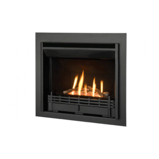
Direct Vent Gas Fireplace Heater
WARNING: If the information in these
instructions is not followed exactly, a fi re
or explosion may result causing property
damage, personal injury or loss of life.
Do not store or use gasoline or other
fl ammable vapors and liquids in the vicinity
of this or any other appliance.
WHAT TO DO IF YOU SMELL GAS
• Do not try to light the appliance.
• Do not touch any electrical switch; do not
use any phone in your building.
• Immediately call your gas supplier from
a neighbor's phone. Follow the gas
supplier's instructions.
• If you cannot reach your gas supplier, call
the fi re department.
Installation and service must be performed
by a qualifi ed installer, service agency or the
gas supplier.
4001950-13
© 2011, Miles Industries Ltd. All rights reserved.
H
ORIZON
Model 534ILN (Natural Gas)
Model 534ILP (Propane)
Installation & Operating Instructions
HOT GLASS WILL
CAUSE BURNS.
DO NOT TOUCH GLASS
UNTIL COOLED.
NEVER ALLOW CHILDREN
TO TOUCH GLASS.
Manufactured by
MILES INDUSTRIES LTD., British Columbia, Canada
www.valorfi replaces.com
INSTALLER: Leave this manual
with the appliance.
CONSUMER: Retain this manual
for future reference.
Please read this manual
BEFORE installing and
operating this appliance.
This appliance may be installed in an
after-market permanently located,
manufactured (mobile) home where not
prohibited by local codes.
This appliance is only for use with the type
of gas indicated on the rating plate. This
appliance is not convertible for use with
other gases, unless a certifi ed kit is used.
This appliance is a domestic room-heating
appliance. It must not be used for any other
purposes such as drying clothes, etc.
This appliance is suitable for installation in a
bedroom or bed sitting room.
Massachusetts: The piping and fi nal
gas connection must be performed by a
licensed plumber or gas fi tter in the State of
Massachusetts. Also, see Carbon Monoxide
Detector requirements under "Safety and
Warning Information" on page 5.

Advertisement

Table of Contents
loading

Summary of Contents for Valor Horizon 534ILN

  • Page 1 Installation and service must be performed Warning Information” on page 5. by a qualifi ed installer, service agency or the gas supplier. Manufactured by MILES INDUSTRIES LTD., British Columbia, Canada www.valorfi replaces.com 4001950-13 © 2011, Miles Industries Ltd. All rights reserved.
  • Page 2 Thank You ... For purchasing a Valor by Miles Industries. Your new radiant gas heater is a technical appliance that must be installed by a qualifi ed dealer. Each Valor fi replace is fully tested during the production process for your safety and comfort.
  • Page 3: Table Of Contents

    Table of Contents Safety and Warning Information ..............4 Specifi cations ....................7 Overview.....................8 Dimensions ....................9 Framing ....................10 Location ....................11 Venting ......................11 Co-Axial Venting ..................12 Co-Linear Venting ..................18 Appliance Preparation ................19 Gas Supply Installation ................23 Liner Panels Installation .................24 Ceramic Logs Installation ...............25 Window Refi...
  • Page 4: Safety And Warning Information

    Safety and Warning Information READ and UNDERSTAND all instructions carefully This unit MUST be used with a vent system as before starting the installation. FAILURE TO described in this installation manual. NO OTHER vent FOLLOW these installation instructions may result in system or components MAY BE USED.
  • Page 5 Safety and Warning Information a. In the event that the side wall horizontally vented Operating Your Fireplace for the First Time gas fueled equipment is installed in a crawl space or When operating your new fi replace for the fi rst time, an attic, the hard wired carbon monoxide detector with some vapors may be released due to the burning of alarm and battery back-up may be installed on the next...
  • Page 6 Safety and Warning Information (c) MANUFACTURER REQUIREMENTS - GAS EQUIPMENT VENTING SYSTEM PROVIDED. When the manufacturer of Product Approved side wall horizontally vented gas equipment provides a venting system design or venting system components with the equipment, the instructions provided by the manufacturer for installation of the equipment and the venting system shall include: 1.
  • Page 7: Specifi Cations

    Approvals & codes Supply Gas These appliances are certifi ed by ANSI Z21.88-2009/CSA Heater engine unit 534ILN is used with natural gas 2.33-2009 American National Standard / CSA Standard installations. for Vented Gas Fireplace Heaters for use in Canada and Heater engine unit 534ILP is used with propane gas USA.
  • Page 8: Overview

    Overview Note: A non-combustible cement board is required above the fi replace when converting to higher input using the 534HNK/534HPK conversion kits. Refer to the instructions provided with the conversion kits for details. Mantel—See Dimensions section for mantel clearances Remote Handset Wall Holder Framing—See Framing section Fire On/Off Wall Switch (optional)
  • Page 9: Dimensions

    Dimensions 7” (180 mm) Stand-offs From finished wall front to top vent 1-1/2” (38 mm) Stand-offs 3” (75 mm) min. To side wall from inner frame 4-1/2” in front of (114 mm) the appliance 36” (914 mm) min. See table 32-3/16”...
  • Page 10: Framing

    Framing • A non-combustible hearth is not necessary in front of this appliance. • Note that the unit is installed at the framing stage and fi xed to framing using support angles. See page 20. Wall fi nish is then installed over the support angles up to the black frame on the unit. NOTE: If using a 613CCB front, refer to the kit’s instruction manual for framing dimensions.
  • Page 11: Location

    Location Venting Vent Material Vent Penetration through Walls & Ceilings This unit is approved for installation using 4 x 6-5/8 Combustible: When penetrating through combustible inches approved co-axial direct vent pipes and acces- walls and ceilings, frame a minimum of 10 inch x 10 sories listed on pages 37–38 of this guide.
  • Page 12: Co-Axial Venting

    Co-Axial Venting Typical Co-Axial Venting Components VERTICAL TERMINATION STORM COLLAR FLASHING ATTIC INSULATION SHIELD HORIZONTAL 2-PIECE TERMINATION WALL ATTIC THIMBLE FIRESTOP CEILING FIRESTOP PIPE 90˚ ELBOW PIPE LENGTH LENGTH PIPE LENGTH PIPE LENGTH 817VAK 817VAK...
  • Page 13 Co-Axial Venting Rear Vent with No Vertical Rise The horizontal vent run cannot be extended by the use of any vent accessory pipes. 26” (66 cm) max. vent length (14” (36 cm) max. Vent pipe max. enclosed within 15” (38 cm) combustible wall after 45°...
  • Page 14 Co-Axial Venting Horizontal Vent Termination Location • The vent terminal must be located on an outside wall or through the roof. • This direct vent appliance is designed to operate when an undisturbed airfl ow hits the outside vent terminal from any direction.
  • Page 15 Co-Axial Venting Co-Axial Venting Confi gurations with Vertical Rise 4 x 90º ELBOWS MAXIMUM (or equivalent) 3” min. above top of horizontal pipe 1” min. all around vertical pipe 1” min. around bottom & sides of horizontal pipe Min. 6” rise for top outlet Min.
  • Page 16 Co-Axial Venting 5. Each 90 degrees elbow installed on the horizontal How to Read the Venting Chart plane is equivalent to a 3 feet horizontal pipe; The chart below applies to co-axial roof or wall therefore, 3 feet must be subtracted from allowable termination in installations with vertical rise.
  • Page 17 Co-Axial Venting Co-Axial Vertical Installations Overhang should • Check the roof pitch to determine which roof not extend beyond vent if within 48” of fl ashing will be needed. See venting accessories list Horizontal termination cap on pages 37–38 for allowable components. overhang •...
  • Page 18: Co-Linear Venting

    Co-Linear Venting Co-Linear Vent Installations Approved co-linear termination or approved • The chimney and fi replace opening sizes are shown in co-linear adapter 3” min. and approved Dimensions and Location sections of this manual. 2 x 3” bend radius Flashing co-axial liners termination...
  • Page 19: Appliance Preparation

    Appliance Preparation Window Removal 1. Turn the top two spring-loaded window bolts through 90 degrees to release the window from the fi rebox. 2. Remove the bottom two spring-loaded window bolts. 3. Carefully lift the window away. Keep the window and bolts in a safe place. Rear Vent Outlet Positioning If installing with top vent outlet, ignore this stage.
  • Page 20 Appliance Preparation Top Heat Shield & Stand-offs Fitting Shield to rest 1. If installing appliance with top vent outlet, on 2 supports remove the plate covering the vent hole in the top heat shield by unscrewing four screws. If installing with rear vent outlet, the plate must remain to cover the hole.
  • Page 21 Appliance Preparation Air Restrictors Fitting No restrictors are required for appliances which only have a horizontal vent run. If installing an appliance which has a rear vent outlet connection and no vertical vent pipe rise, ignore this stage. A restrictor set, shown right, is supplied with each 534 engine unit. The restrictors cover part of the inlet air openings in the fi...
  • Page 22 Appliance Preparation Rear Log Support Refi tting Refi t the rear log support in place (5 screws). Appliance Framing 1. Place the heater in position in the framing. 2. Secure the side support angles to the side studding through two holes each side with the woodscrews Reinstall rear log support supplied.
  • Page 23: Gas Supply Installation

    Gas Supply Installation • The gas supply pipe should enter the appliance case through the opening at the left side. The supply pipe should be connected to the appliance gas inlet pipe situated at the left side of the control valve. Supply line connection to the inlet pipe is 3/8 inch NPT ( female).
  • Page 24: Liner Panels Installation

    Liner Panels Installation All liner panels can be installed as indicated below. 4. Insert the top panel over the left side panel while Unpack the liners carefully to avoid scratching or holding the top panel forward up the slope. Rotate damaging them.
  • Page 25: Ceramic Logs Installation

    Ceramic Logs Installation Unpack the ceramic logs very carefully to avoid damaging their fragile material. Install the logs as shown below. Please note that the position of the logs is critical to insure the good performance of the appliance. 1. Place the rear log centering it side to side in the 4.
  • Page 26: Window Refi Tting & Checking

    Window Refi tting & Checking 1. Refi t the window with the bottom two bolts. The bolts should be screwed in securely. 2. Refi t the top two bolts securing by turning them through 90 degrees. 3. Pull the top of the window forward and release to check that it opens slightly and returns confi...
  • Page 27: Operation Check & Aeration Settings Adjustment

    Operation Check & Aeration Settings Adjustment Operation Check In a few unusual installations, the fl ame picture may Turn the fi replace fl ame up and down using the be improved by adjusting the aeration. The need for remote control to confi rm that the full range of inputs adjustment should be determined only by operating the is achieved—see the remote control operation appliance with the ceramic rocks and window installed.
  • Page 28: Owner's Information

    1. Refi t the window with the bottom two bolts. The particular case. bolts should be screwed in securely. NOTE: This is a problem beyond Miles Industries’ 2. Refi t the top two bolts securing by turning them control and is not covered under warranty.
  • Page 29 Owner’s Information Soot or dust can be brushed from the ceramic rocks Batteries and fi rebox walls using a soft brush. Dust can also CAUTION be removed from the burner using a soft brush after DO NOT USE a screwdriver or other metallic removing the ceramic logs.
  • Page 30 Owner’s Information Manual On/Off Switch In cases where you want to turn off your fi replace and cannot do it with the remote control handset (misplaced, lost, dead batteries, etc.) or if you need to replace the receiver’s batteries, you can turn off the appliance with the manual switch located on the right hand side of the valve.
  • Page 31: Remote Control Operation

    Remote Control Operation NOTE: Before using the remote control system for the fi rst time, the receiver and the handset must be synchronized. See the section Remote Control Initial Set-up on page 26 in this manual. Your fi replace remote control helps you get the comfort, convenience and aesthetics you want from your gas fi replace. The remote controls your fi...
  • Page 32 Remote Control Operation Operation Modes STANDBY MODE—Ignited pilot only. MAN MODE —Manual Mode. You can use this mode to adjust the flame height up or down. ☼ TEMP MODE —Daytime Temperature Mode (appliance must be in Standby mode; pilot ignited): The room temper- TEMP ature is measured and compared to the set temperature.
  • Page 33 Remote Control Operation Temperature Use this setting when you come in and want to enjoy a set temperature. MODE or the ☽ 1. Select either the ☼ MODE by briefly pressing the SET button. TEMP TEMP 2. Hold the SET button until the TEMP display flashes. 3.
  • Page 34: Options

    Remote Control Operation Low Battery Indication CAUTION Remote handset: BATT will appear on the display when DO NOT USE a screwdriver or other metallic object the battery needs to be replaced. to remove the batteries from the battery box or the Replace with one 9 V alkaline battery.
  • Page 35: Lighting Instructions

    Lighting Instructions FOR YOUR SAFETY, READ BEFORE LIGHTING WARNING : If you do not follow these instructions exactly a re or ex losion ay result causin ro erty da a e ersonal in ury or loss of life A. This appliance has a pilot which must be lighted by hand or by remote control. Follow these instructions exactly. To save gas, turn the pilot off when not using the appliance for a prolonged period of time.
  • Page 36: Wiring Diagram

    Wiring Diagram Optional Wall Switch Kit 1265WSK Connector Yellow GV60 Wiring Diagram...
  • Page 37: Approved Venting Components

    Approved Venting Components APPROVED DIRECT VENT SUPPLIERS FOR VALOR MODELS 530, 534, 535, 650, AND MF28 Venting Parts Code / availability by Manufacturer Venting Parts Description Co-axial Kit, 26” long — — — — — 551DVK Standard Co-axial 46DVA-HC 4DT-HC TM-4HT —...
  • Page 38 Approved Venting Components Venting Parts Code / availability by Manufacturer Venting Parts Description Galvanized 46DVA-06 4DT-06 TC-4DL6 SV4L6 6” long — — Black 46DVA-06B 4DT-06(B) TC-4DL6B SV4LB6 Galvanized 46DVA-09 4DT-09 — 9” long — — — Black 46DVA-09B 4DT-09(B) — Galvanized 46DVA-12 4DT-12...
  • Page 39: Warranty

    1. Extended Warranty Coverage For a period of up to ten (10) years, Miles Industries Ltd., (the “Company”) or its appointed distributor will at its option pay the initial purchaser for the repair of, or will exchange the following parts or components which are found to be defective in material or...
  • Page 40: Replacement Parts

    Replacement Parts Key Description Part no. Key Description Part no. Top stand-offs (2) 3000192 Pipe—valve to main burner 3000247 Top heat shield panel 350A008 Burner plate 4001966 Top frame support angle bracket 3000181 Gaskets—module plate sides (2) 3000399 Outer vent collar 330A888 Gaskets—module plate front &...
  • Page 41 Replacement Parts Key Description Part no. Valor red brick 4002106 Ledgestone 4002114 Log set complete 4001696 Rear log 4001697 Front left log 4001699 Front right log 4001700 Right cross log 4001701 Middle cross log 4001698 Left cross log 4001772...
  • Page 43 Reason for Purchase: Performance Flame Appeal Design Control Previous owner Recommendation Price Other Dealer Name: Address: City: Province/State: Postal Code/Zip: Phone: ( Cut out page, fi ll information, and mail to Miles Industries Ltd. Online Warranty registration at www.valorfi replaces.com...
  • Page 44 Tape Shut Fold here Postage needed Miles Industries Ltd. 190 - 2255 Dollarton Highway North Vancouver, BC V7H 3B1 Canada Online Warranty registration at www.valorfi replaces.com Were you given all documentation and manuals for your product? Thank you for choosing a Valor Product...

This manual is also suitable for:

Horizon 534ilp

Table of Contents