
Related Manuals for Supero SuperServer 5016T-MRB


Summary of Contents for Supero SuperServer 5016T-MRB
- Page 1 ® UPER 5016T-MRB UPER ERVER 5016T-MR-LN4B UPER ERVER USER’S MANUAL Revision 1.0a...
- Page 2 This product, including software and docu- mentation, is the property of Supermicro and/or its licensors, and is supplied only under a license. Any use or reproduction of this product is not allowed, except as expressly permitted by the terms of said license.
-
Page 3: About This Manual
LEDs located throughout the system. Chapter 4: System Safety You should thoroughly familiarize yourself with this chapter for a general overview of safety precautions that should be followed when installing and servicing the SuperServer 5016T-MRB/5016T-MR-LN4B. - Page 4 UPER ERVER 5016T-MRB/5016T-MR-LN4B User's Manual Chapter 5: Advanced Motherboard Setup Chapter 5 provides detailed information on the X8STi/X8STi-LN4 motherboard, including the locations and functions of connectors, headers and jumpers. Refer to this chapter when adding or removing processors or main memory and when reconfi...
- Page 5 Preface Notes...
-
Page 6: Table Of Contents
UPER ERVER 5016T-MRB/5016T-MR-LN4B User's Manual Table of Contents Chapter 1 Introduction Overview ......................1-1 Motherboard Features ..................1-2 Processor ......................1-2 Memory ......................1-2 Onboard SATA ....................1-2 PCI Expansion Slots ..................1-2 Onboard Controllers/Ports ................1-2 Server Chassis Features ................1-4 System Power .................... - Page 7 Table of Contents Checking the Drive Bay Setup ..............2-10 Chapter 3 System Interface Overview ......................3-1 Control Panel Buttons ..................3-1 Reset ....................... 3-1 Power ......................3-1 Control Panel LEDs ..................3-2 Overheat ......................3-2 NIC2 ........................ 3-2 NIC1 ........................ 3-2 HDD .........................
- Page 8 UPER ERVER 5016T-MRB/5016T-MR-LN4B User's Manual Main ATX Power Supply Connector ............5-14 Processor Power Connector ..............5-14 Power Button .................... 5-14 Reset Button ..................... 5-14 Power Fail LED ..................5-14 Overheat/Fan Fail/UID LED ..............5-15 NIC2 (LAN2) LED ..................5-15 NIC1 (LAN1) LED ..................
- Page 9 Table of Contents LAN LEDs ....................5-23 Onboard Power LED (LE1) ..............5-23 UID LED ....................5-23 BMC Heartbeat LED ................5-23 SAS Activity LED (X8STi only) ..............5-24 SAS Heartbeat LED (X8STi only) ............5-24 5-12 Floppy and SATA and SAS Ports ..............5-25 Floppy Drive Connector ................
- Page 10 UPER ERVER 5016T-MRB/5016T-MR-LN4B User's Manual Notes...
-
Page 11: Chapter 1 Introduction
Overview The Supermicro SuperServer 5016T-MRB/5016T-MR-LN4B is a high-end, single- processor server. The 5016T-MRB/5016T-MR-LN4B is comprised of two main sub- systems: the SC512-200B mini 1U chassis and the X8STi/X8STi-LN4 motherboards, respectively. Please refer to our web site for information on operating systems that have been certifi... -
Page 12: Motherboard Features
3 Gb/sec Serial ATA subsystem. The SATA drive is not hot-swappable. PCI Expansion Slots The X8STi/X8STi-LN4 has one PCI-E 2.0 x16 slot for use in the 5016T-MRB/5016T- MR-LN4B server. The PCI-E slots may be populated with a riser card (included). Onboard Controllers/Ports An onboard IDE controller supports one fl... - Page 13 Chapter 1: Introduction Intel Intersil DDR3-1333/1066/800 VRD 11.1 LGA1366 CPU (Channel A, B, C) QPI: Up to 6.40 GT/s PCI-E_x8 PCI-E Gen1 x8 (in x4) PCI-E x16 PCI-E Gen2 x16 Intel RJ45 PCI-E x1 RJ45 Intel 82574L Intel 82574L PCI-E x1 RJ45 (X8STi-LN4 only) PCI-E x1...
-
Page 14: Server Chassis Features
UPER ERVER 5016T-MRB/5016T-MR-LN4B User's Manual Server Chassis Features The SC512-200 is a mini 1U rackmount server platform confi guration. The following is a general outline of the main features of the SC512-200 chassis. System Power When confi gured as a SuperServer 5015B-MF, the SC512-200 chassis includes a single 200W power supply. -
Page 15: Contacting Supermicro
Super Micro Computer, Inc. 980 Rock Ave. San Jose, CA 95131 U.S.A. Tel: +1 (408) 503-8000 Fax: +1 (408) 503-8008 Email: marketing@supermicro.com (General Information) support@supermicro.com (Technical Support) Web Site: www.supermicro.com Europe Address: Super Micro Computer B.V. Het Sterrenbeeld 28, 5215 ML... - Page 16 UPER ERVER 5016T-MRB/5016T-MR-LN4B User's Manual Notes...
-
Page 17: Chapter 2 Server Installation
An optional rack rail package is available if you wish to order from Supermicro. Follow the steps in the order given to complete the installation process in a minimal amount of time. -
Page 18: Rack Precautions
UPER ERVER 5016T-MRB/5016T-MR-LN4B User's Manual installation only in a Restricted Access Location (dedicated equipment rooms, service closets and the like). • This product is not suitable for use with visual display work place devices acccording to §2 of the the German Ordinance for Work with Visual Display Units. -
Page 19: Rack Mounting Considerations
Chapter 2: Server Installation Rack Mounting Considerations Ambient Operating Temperature If installed in a closed or multi-unit rack assembly, the ambient operating tempera- ture of the rack environment may be greater than the ambient temperature of the room. Therefore, consideration should be given to installing the equipment in an environment compatible with the manufacturer’s maximum rated ambient tempera- ture (Tmra). -
Page 20: Installing The System Into A Rack
Installing the System into a Rack (Rack hardware optional) This section provides information on installing the SuperServer 5016T-MRB/5016T- MR-LN4B into a rack unit. If the system has already been mounted into a rack, you can skip ahead to Sections 2-5 and 2-6. -
Page 21: Installing The Chassis Rails
Chapter 2: Server Installation Installing the Chassis Rails The two rail sections must be detached from each other prior to installation: depress the locking tab on the inner rail to release it from its locked position then pull the two rails completely apart. -
Page 22: Installing The Server Into The Rack
UPER ERVER 5016T-MRB/5016T-MR-LN4B User's Manual Installing the Server into the Rack You should now have rails attached to both the chassis and the rack unit. The next step is to install the server into the rack. Do this by lining up the rear of the chassis rails with the front of the rack rails. -
Page 23: Installing The Server Into A Telco Rack
Chapter 2: Server Installation Figure 2-4. Installing the Server into a Rack: w/ Rackmount Kit Installing the Server into a Telco Rack To install the server into a Telco type rack, use two L-shaped brackets on either side of the chassis (four total). First, determine how far the server will extend out the front of the rack. -
Page 24: Checking The Motherboard Setup
Figure 2-5. Installing the Server into a Telco Rack: Basic Checking the Motherboard Setup After you install the 5016T-MRB/5016T-MR-LN4B in the rack, you will need to open the unit to make sure the motherboard is properly installed and all the connections have been made. - Page 25 Chapter 2: Server Installation Figure 2-6. Installing the Server into a Telco Rack: w/ Rackmount Kit Next, depress the two buttons on the top of the chassis to release the top cover while pushing the cover away from you until it stops. You can then lift the top cover from the chassis to gain full access to the inside of the server.
-
Page 26: Checking The Drive Bay Setup
UPER ERVER 5016T-MRB/5016T-MR-LN4B User's Manual Figure 2-7. Accessing the Inside of the System Make sure all power and data cables are properly connected and not block- ing the airfl ow. See Chapter 5 for details on cable connections. Also, check the air seals for damage. - Page 27 Chapter 2: Server Installation Checking the Airfl ow Airfl ow is provided by one 10-cm input fan. The system component layout was carefully designed to promote suffi cient airfl ow through the small 1U rackmount space. Note that all power and data cables have been routed in such a way that they do not block the airfl...
- Page 28 UPER ERVER 5016T-MRB/5016T-MR-LN4B User's Manual Notes 2-12...
-
Page 29: Chapter 3 System Interface
Chapter 3: System Interface Chapter 3 System Interface Overview There are several LEDs on the control panel to keep you constantly informed of the overall status of the system as well as the activity and health of specifi c com- ponents. -
Page 30: Control Panel Leds
UPER ERVER 5016T-MRB/5016T-MR-LN4B User's Manual Control Panel LEDs The control panel located on the front of the SC512-200 chassis has fi ve LEDs. These LEDs provide you with critical information related to different parts of the system. This section explains what each LED indicates when illuminated and any corrective action you may need to take. -
Page 31: Power
Chapter 3: System Interface Power Indicates power is being supplied to the system's power supply units. This LED should normally be illuminated when the system is operating. - Page 32 UPER ERVER 5016T-MRB/5016T-MR-LN4B User's Manual Notes...
-
Page 33: Chapter 4 System Safety
System Safety Electrical Safety Precautions Basic electrical safety precautions should be followed to protect yourself from harm and the SuperServer 5016T-MRB/5016T-MR-LN4B from damage: • Be aware of the locations of the power on/off switch on the chassis as well as the room's emergency power-off switch, disconnection switch or electrical outlet. -
Page 34: General Safety Precautions
Keep the area around the 5016T-MR/5016T-MR-LN4 clean and free of clutter. • The 5016T-MRB/5016T-MR-LN4B weighs approximately 16.5 lbs (7.5 kg) when fully loaded. When lifting the system, two people at either end should lift slowly with their feet spread out to distribute the weight. Always keep your back straight and lift with your legs. -
Page 35: Esd Precautions
Chapter 4: System Safety • After accessing the inside of the system, close the system back up after ensuring that all connections have been made. ESD Precautions Electrostatic discharge (ESD) is generated by two objects with different electrical charges coming into contact with each other. An electrical discharge is created to neutralize this difference, which can damage electronic com ponents and printed circuit boards. -
Page 36: Operating Precautions
UPER ERVER 5016T-MRB/5016T-MR-LN4B User's Manual Operating Precautions Care must be taken to assure that the chassis cover is in place when the 5016T- MRB/5016T-MR-LN4B is operating to assure proper cooling. Out of warranty dam- age to the system can occur if this practice is not strictly followed. -
Page 37: Chapter 5 Advanced Serverboard Setup
Chapter 5: Advanced Serverboard Setup Chapter 5 Advanced Serverboard Setup This chapter covers the steps required to install the X8STi/X8STi-LN4 serverboard into the chassis, connect the data and power cables and install add-on cards. All serverboard jumpers and connections are also described. A layout and quick refer- ence chart are included in this chapter for your reference. -
Page 38: Unpacking
UPER ERVER 5016T-MRB/5016T-MR-LN4B User's Manual Unpacking The serverboard is shipped in antistatic packaging to avoid electrical static dis- charge. When unpacking the board, make sure the person handling it is static protected. Serverboard Installation This section explains the fi rst step of physically mounting the X8STi/X8STi-LN4 into the SC512-200B chassis. -
Page 39: Connecting Cables
Chapter 5: Advanced Serverboard Setup Connecting Cables Now that the serverboard is installed, the next step is to connect the cables to the board. These include the data cables for the peripherals and control panel and the power cables. Connecting Data Cables The cables used to transfer data from the peripheral devices have been carefully routed to prevent them from blocking the fl... -
Page 40: I/O Ports
UPER ERVER 5016T-MRB/5016T-MR-LN4B User's Manual Figure 5-1. Control Panel Header Pins Ground x (Key) x (Key) Power On LED HDD LED/UID Switch NIC1 LED NIC2 LED OH/Fan Fail/UID LED Vcc/UID LED Power Fail LED Ground Reset (Button) Ground Power (Button) I/O Ports The I/O ports are color coded in conformance with the PC 99 specifi... -
Page 41: Installing The Processor And Heatsink
LGA1366 processor pre-installed, make sure that the plastic CPU cap is in place and none of the CPU pins are bent; otherwise, contact your retailer immediately. Refer to the Supermicro web site for more details on supported CPUs. Installing an LGA1366 Processor Press the socket clip to release... - Page 42 UPER ERVER 5016T-MRB/5016T-MR-LN4B User's Manual After removing the plastic cap, use your thumb and the index fi nger to hold the CPU at the north and south center edges. Align the CPU key (the semi-circle cutout) with the socket key (the notch below the gold color dot on the side of the socket).
-
Page 43: Installing A Passive Cpu Heatsink
Chapter 5: Advanced Serverboard Setup Installing a Passive CPU Heatsink Screw#4 Notes: The motherboard comes with a heatsink bracket pre-in- stalled on the reverse side of the board. Do not apply any thermal grease to the heatsink or the CPU die;... -
Page 44: Removing The Heatsink
UPER ERVER 5016T-MRB/5016T-MR-LN4B User's Manual Removing the Heatsink Warning: We do not recommend that the CPU or the heatsink be re- moved. However, if you do need to remove the heatsink, please follow the instructions below prevent damage to the CPU or other components. -
Page 45: Installing Memory Modules
Chapter 5: Advanced Serverboard Setup Installing Memory Modules Note: Check the Supermicro web site for recommended memory modules. CAUTION Exercise extreme care when installing or removing DIMM modules to prevent any possible damage. Press down the release tabs Installing & Removing DIMMs Insert the desired number of DIMMs into the memory slots, starting with DIMM #1A. -
Page 46: Memory Support
UPER ERVER 5016T-MRB/5016T-MR-LN4B User's Manual Memory Support The X8STi/X8STi-LN4 supports up to 24 GB of unbuffered ECC or non-ECC DDR3 1333/1066/800 in 6 DIMM slots. Populating the DIMM slots with a pair (or pairs) of memory modules of the same type and size will result in interleaved memory, which will improve memory performance. -
Page 47: Pci Expansion Cards
Chapter 5: Advanced Serverboard Setup PCI Expansion Cards The SC512-200 chassis uses a riser card to accommodate one add-on card (CSE- RR1U-E16 for a PCI-E x16 card. Installing a PCI Expansion Card After powering down the system, remove the PCI slot shield. Fully seat the riser card into the slot, pushing down with your thumbs evenly on both sides of the card. -
Page 48: Serverboard Details
UPER ERVER 5016T-MRB/5016T-MR-LN4B User's Manual Serverboard Details Figure 5-4. X8STi/X8STi-LN4 Layout (not drawn to scale) LSI 1068E Notes Jumpers not indicated are for testing purposes only. The X8STi-LN4 includes two additional LAN ports but no SAS components. See section 5-11 for descriptions of the onboard LEDs. -
Page 49: X8Sti/X8Sti-Ln4 Quick Reference
Chapter 5: Advanced Serverboard Setup X8STi/X8STi-LN4 Quick Reference Jumper Description Default Setting JBMC1 BMC Enable/Disable Pins 1-2 (Enabled) JBT1 CMOS Clear (See Section 5-10) C1/JI SMB to PCI Slots Closed (Disabled) JPG1 VGA Enable/Disable Pins 1-2 (Enabled) JPL1/JPL2 LAN 1/2 Enable/Disable Pins 1-2 (Enabled) JPS1* SAS Controller Enable/Disable... -
Page 50: Connector Defi Nitions
UPER ERVER 5016T-MRB/5016T-MR-LN4B User's Manual Connector Defi nitions ATX Power 24-pin Connector Pin Defi nitions (JPW1) Pin# Defi nition Pin # Defi nition Main ATX Power Supply +3.3V +3.3V Connector -12V +3.3V The 24-pin primary power supply connector (JPW1) meets the SSI PS_ON EPS 12V specification. -
Page 51: Overheat/Fan Fail/Uid Led
Chapter 5: Advanced Serverboard Setup Overheat/Fan Fail/UID LED OH/Fan Fail/UID LED OH/Fan Fail Indicator Pin Defi nitions (JF1) Status Connect an LED to pins 7 and 8 of JF1 Pin# Defi nition State Defi nition to provide UID signals and advanced Vcc/UID LED Normal warning of chassis overheating. -
Page 52: Nmi Button
UPER ERVER 5016T-MRB/5016T-MR-LN4B User's Manual NMI Button NMI Button Pin Defi nitions (JF1) The non-maskable interrupt button Pin# Defi nition header is located on pins 19 and 20 Control of JF1. Refer to the table on the right Ground for pin defi nitions. -
Page 53: Chassis Intrusion
Chapter 5: Advanced Serverboard Setup Chassis Intrusion Chassis Intrusion The Chassis Intrusion header is des- Pin Defi nitions (JL1) ignated JL1. Attach an appropriate Pin# Defi nition cable from the chassis to inform you Intrusion Input of a chassis intrusion when the chas- Ground sis is opened Wake-On-LAN... -
Page 54: Universal Serial Bus (Usb)
UPER ERVER 5016T-MRB/5016T-MR-LN4B User's Manual Universal Serial Bus (USB) Universal Serial Bus Pin Defi nitions (USB) There are two Universal Serial Bus USB0/1 USB4/5/6/7 ports located on the I/O panel. An Pin # Defi nition Pin # Defi nition additional six USB headers are in-... -
Page 55: Power Supply Fail Led Header
See the table on the right for Signal: Alarm Reset pin defi nitions. Note: This feature is only available when using Supermicro redundant power supplies. Alarm Reset Alarm Reset If three power supply modules are Pin Defi nitions (JAR) -
Page 56: 5-10 Jumper Settings
UPER ERVER 5016T-MRB/5016T-MR-LN4B User's Manual 5-10 Jumper Settings Explanation of Jumpers To modify the operation of the serverboard, jumpers can be used Connector to choose between optional settings. Pins Jumpers create shorts between two pins to change the function of the con- nector. -
Page 57: Lan1/2 Enable/Disable
Chapter 5: Advanced Serverboard Setup LAN1/2 Enable/Disable Change the setting of jumper JPL1 LAN1/2 En/Disable Jump- er Settings (JPL1/JPL2) and JPL2 to enable or disable the Jumper Setting Defi nition LAN1 and LAN2 Ethernets ports, re- Pins 1-2 Enabled spectively. See the table on the right Pins 2-3 Disabled for jumper settings. -
Page 58: Smbus To Pci Slots
UPER ERVER 5016T-MRB/5016T-MR-LN4B User's Manual SMBus to PCI Slots Jumpers JI C1 and JI C2 allow you to connect the System Management Bus SMBus to PCI Slots Jumper Settings (JI C1/JI C) to the PCI slot. The default set- Jumper Setting Defi... -
Page 59: 5-11 Onboard Indicators
Chapter 5: Advanced Serverboard Setup 5-11 Onboard Indicators LAN LEDs LAN LED The Ethernet ports (located beside the (Connection Speed Indicator) VGA port) have two LEDs. On each LED Color Defi nition port, one LED indicates activity while NC or 10 Mb/s the other LED may be green, amber Green 100 Mb/s... -
Page 60: Sas Activity Led (X8Sti Only)
UPER ERVER 5016T-MRB/5016T-MR-LN4B User's Manual SAS Activity LED (X8STi only) The SAS Activity LED is designated as LES1. When LES1 blinks, it indi- cates SAS activity. SAS Heartbeat LED (X8STi only) The SAS Heartbeat LED is desig- nated as LES2. When LES2 blinks, it indicates the SAS ports are ready for use. -
Page 61: 5-12 Floppy And Sata And Sas Ports
Chapter 5: Advanced Serverboard Setup 5-12 Floppy and SATA and SAS Ports Floppy Drive Connector Floppy Drive Connector Pin Defi nitions (Floppy) Pin# Defi nition Pin # Defi nition The fl oppy connector is located Ground FDHDIN near the USB2 port and the Ground Reserved I-Button. -
Page 62: 5-13 Installing Software
5-13 Installing Software After the hardware has been installed, you should fi rst install the operating system and then the drivers. The necessary drivers are all included on the Supermicro CDs that came packaged with your motherboard. Driver/Tool Installation Display Screen Note: Click the icons showing a hand writing on paper to view the readme fi... -
Page 63: Supero Doctor Iii
Chapter 5: Advanced Serverboard Setup Supero Doctor III The Supero Doctor III program is a Web base management tool that supports remote management capability. It includes Remote and Local Management tools. The local management is called SD III Client. The Supero Doctor III program included on the CD-ROM that came with your motherboard allows you to monitor the environment and operations of your system. - Page 64 Supero Doctor III Interface Display Screen (Remote Control) Note: SD III Software Revision 1.0 can be downloaded from our Web Site at: ftp://ftp. supermicro.com/utility/Supero_Doctor_III/. You can also download the SDIII User's Guide at: <http://www.supermicro.com/PRODUCT/Manuals/SDIII/UserGuide.pdf>. For Linux, we will recommend using Supero Doctor II.
-
Page 65: Chapter 6 Advanced Chassis Setup
Chapter 6: Advanced Chassis Setup Chapter 6 Advanced Chassis Setup This chapter covers the steps required to install components and perform mainte- nance on the SC512C-260 chassis. For component installation, follow the steps in the order given to eliminate the most common problems encountered. If some steps are unnecessary, skip ahead to the step that follows. -
Page 66: Control Panel
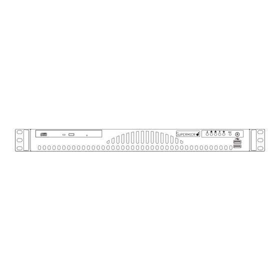
UPER ERVER 5016T-MRB/5016T-MR-LN4B User's Manual Figure 6-1. Chassis Front View Figure 6-2. Chassis Rear View Keyboard/ Mouse Ports USB Ports COM1 Port VGA Port Ethernet Ports Control Panel The control panel (located on the front of the chassis) must be connected to the JF1 connector on the motherboard to provide you with system control buttons and status indicators. -
Page 67: System Fans
System Fan Failure If the fan fails, you will need to have it replaced with the same type. Contact your vendor or Supermicro for information on replacement fans. The fan sits on two mounting posts secured with screws. See Figure 6-3. -
Page 68: Drive Bay Installation/Removal
For installing or removing a DVD-ROM or Serial ATA drive, you will need to gain access to the inside of the 5016T-MRB/5016T-MR-LN4B by removing the top cover of the chassis. The DVD-ROM drive is an optional component in the server. - Page 69 Replace the DVD-ROM drive and the top cover when fi nished. Enterprise level hard disk drives are recommended for use in Supermicro chassis and servers. For information on recommended HDDs, visit the Supermicro Web site at http://www.supermicro.com/products/nfo/fi les/ storage/SAS-1-CompList-110909.pdf...
-
Page 70: Power Supply
Power Supply Failure If the power supply unit fails, the system will shut down and you will need to replace the power supply unit. Replacement units can be ordered directly from Supermicro (PWS-201-1H - see contact infomation in Chapter 1). -
Page 71: Chapter 7 Bios
When an option is selected in the left frame, it is highlighted in white. Often a text message will accompany it. (Note: the AMI BIOS has default text messages built in. Supermicro retains the option to include, omit, or change any of these text messages.) The AMI BIOS Setup Utility uses a key-based navigation system called "hot keys". -
Page 72: Starting The Setup Utility
Warning! Do not upgrade the BIOS UNLESS your system has a BIOS- related issue. Flashing the wrong BIOS can cause irreparable damage to the system. In no event shall Supermicro be liable for direct, indirect, special, incidental, or consequential damages arising from a BIOS update. If you have to update the BIOS, do not shut down or reset the system while the BIOS is updating. - Page 73 Chapter 7: BIOS Day MM/DD/YY format. The time is entered in HH:MM:SS format. (Note: The time is in the 24-hour format. For example, 5:30 P.M. appears as 17:30:00.) AMIBIOS Version Build Date Processor The AMI BIOS will automatically display the status of processor as shown below: Type of Processor Speed Physical Count...
-
Page 74: Advanced Setup Confi Gurations
UPER ERVER 5016T-MRB/5016T-MR-LN4B User's Manual Advanced Setup Confi gurations Use the arrow keys to select Boot Setup and hit <Enter> to access the submenu items: BOOT Feature Quick Boot If Enabled, this option will skip certain tests during POST to reduce the time needed for system boot. - Page 75 Chapter 7: BIOS Wait For 'F1' If Error This forces the system to wait until the 'F1' key is pressed if an error occurs. The options are Disabled and Enabled. Hit 'Del' Message Display This feature displays "Press DEL to run Setup" during POST. The options are Enabled and Disabled.
- Page 76 UPER ERVER 5016T-MRB/5016T-MR-LN4B User's Manual Clock Spread Spectrum Select Enable to use the feature of Clock Spectrum, which will allow the BIOS to monitor and attempt to reduce the level of Electromagnetic Interference caused by the components whenever needed. The options are Disabled and Enabled.
- Page 77 Chapter 7: BIOS tion and heat dissipation. Please refer to Intel’s web site for detailed information. The options are Disable: Disable GV3 and Enable: Enable GV3. Intel® TurboMode Tech (Available if Intel® EIST technology is Enabled) This feature allows processor cores to run faster than marked frequency in specifi c conditions.
-
Page 78: Advanced Chipset Control
UPER ERVER 5016T-MRB/5016T-MR-LN4B User's Manual C-STATE Tech If enabled, C-State is set by the system automatically to either C2, C3 or C4 state. The options are Disabled and Enabled. C-State package limit setting If set to Auto, the AMI BIOS will automatically set the limit on the C-State package register. - Page 79 Chapter 7: BIOS QPI L0s and L1 Select Enabled to lower the QPI power state. L0s and L1 are automatically selected by the motherboard. The options are Disabled and Enabled. Memory Frequency Use this option to force the system memory to run at a different frequency than the default frequency.
- Page 80 UPER ERVER 5016T-MRB/5016T-MR-LN4B User's Manual Inlet Temperature This is the temperature detected at the chassis inlet. Each step is in 0.5 increment. The default is [070]. Press "+" or "-" on your keyboard to change this value. Temperature Rise This item allows the user to defi ne the temperature rise parameter of a memory module to be used to improve memory power management.
- Page 81 Chapter 7: BIOS Intel VT-d Select Enabled to enable Intel's Virtualization Technology support for Direct I/O VT-d by reporting the I/O device assignments to VMM through the DMAR ACPI Tables. This feature offers fully-protected I/O resource-sharing across the Intel platforms, providing the user with greater reliability, security and availability in networking and data-sharing.
- Page 82 UPER ERVER 5016T-MRB/5016T-MR-LN4B User's Manual IDE / Floppy Confi guration When this submenu is selected, the AMI BIOS automatically detects the presence of the IDE Devices and displays the following items: Floppy A This feature allows the user to select the type of fl oppy drive connected to the sys- tem.
- Page 83 Chapter 7: BIOS activate the following submenu screen for detailed options of these items. Set the correct confi gurations accordingly. The items included in the submenu are: Type Select the type of device connected to the system. The options are Not Installed, Auto, CD/DVD and ARMD.
- Page 84 UPER ERVER 5016T-MRB/5016T-MR-LN4B User's Manual DMA Mode Select Auto to allow the BIOS to automatically detect IDE DMA mode when the IDE disk drive support cannot be determined. Select SWDMA0 to allow the BIOS to use Single Word DMA mode 0. It has a data transfer rate of 2.1 MBs.
- Page 85 Chapter 7: BIOS PCI/PnP Confi guration This feature allows the user to set the PCI/PnP confi gurations for the following items: Clear NVRAM This feature clears the NVRAM during system boot. The options are No and Yes. Plug & Play OS Selecting Yes allows the OS to confi...
- Page 86 UPER ERVER 5016T-MRB/5016T-MR-LN4B User's Manual Super IO Device Confi guration Serial Port1 Address/ Serial Port2 Address This option specifi es the base I/O port address and the Interrupt Request address of Serial Port 1 and Serial Port 2. Select Disabled to prevent the serial port from accessing any system resources.
- Page 87 Chapter 7: BIOS Redirection After BIOS POST Select Disabled to turn off Console Redirection after Power-On Self-Test (POST). Select Always to keep Console Redirection active all the time after POST. (Note: This setting may not be supported by some operating systems.) Select Boot Loader to keep Console Redirection active during POST and Boot Loader.
- Page 88 UPER ERVER 5016T-MRB/5016T-MR-LN4B User's Manual CPU Temperature/System Temperature This feature displays current temperature readings for the CPU and the System. The following items will be displayed for your reference only: System Temperature The item displays the absolute temperature as detected by the BIOS.
- Page 89 Chapter 7: BIOS Fan Speed Control Modes This feature allows the user to decide how the system controls the speeds of the onboard fans. The CPU temperature and the fan speed are correlative. When the CPU on-die temperature increases, the fan speed will also increase, and vice versa. Select Workstation if your system is used as a Workstation.
-
Page 90: Trusted Computing
UPER ERVER 5016T-MRB/5016T-MR-LN4B User's Manual Trusted Computing TCG/TPM Support Select Yes on this item and enable the TPM jumper on the motherboard to enable TCG (TPM 1.1/1.2)/TPM support in order to improve data integrity and network security. The options are No and Yes. - Page 91 Chapter 7: BIOS Clear BMC System Event Log This feature is used to clear the System Event Log. Caution: Any cleared information is unrecoverable. Make absolutely sure you no longer need any data stored in the log before clearing the BMC Event Log. Set LAN Confi...
- Page 92 UPER ERVER 5016T-MRB/5016T-MR-LN4B User's Manual Startup Delay - This feature enables or disables startup delay. The options are Enabled and Disabled. PEF Startup Delay - This sets the pre-determined time to delay PEF after system power-ups and resets. Refer to Table 24.6 of the IPMI 1.5 Specifi cation for more information at www.intel.com.
-
Page 93: Security Settings
Chapter 7: BIOS Security Settings The AMI BIOS provides a Supervisor and a User password. If you use both pass- words, the Supervisor password must be set fi rst. Supervisor Password This item indicates if a supervisor password has been entered for the system. Clear means such a password has not been used and Set means a supervisor password has been entered for the system. -
Page 94: Boot Confi Guration
UPER ERVER 5016T-MRB/5016T-MR-LN4B User's Manual Clear User Password (Available only if User Password has been set) Password Check Available options are Setup and Always. Boot Sector Virus Protection When Enabled, the AMI BOIS displays a warning when any program (or virus) is- sues a Disk Format command or attempts to write to the boot sector of the hard disk drive. -
Page 95: Exit Options
Chapter 7: BIOS Hard Disk Drives This feature allows the user to specify the boot sequence from all available hard disk drives. The settings are Disabled and a list of all hard disk drives that have been detected (i.e., 1st Drive, 2nd Drive, 3rd Drive, etc). Removable Drives This feature allows the user to specify the boot sequence from available Removable Drives. - Page 96 UPER ERVER 5016T-MRB/5016T-MR-LN4B User's Manual fi guration parameters can take effect. Select Save Changes and Exit from the Exit menu and press <Enter>. Discard Changes and Exit Select this option to quit the BIOS Setup without making any permanent changes to the system confi...
-
Page 97: Appendix A Post Error Beep Codes
Appendix A: POST Error Beep Codes Appendix A POST Error Beep Codes This section lists POST (Power On Self Test) error beep codes for the AMI BIOS. POST error beep codes are divided into two categories: recoverable and terminal. This section lists Beep Codes for recoverable POST errors. Recoverable POST Error Beep Codes When a recoverable type of error occurs during POST, BIOS will display a POST code that describes the problem. - Page 98 UPER ERVER 5016T-MRB/5016T-MR-LN4B User's Manual Notes...
-
Page 99: Appendix B Installing The Windows Os
South Bridge RAID Settings before you install the Windows OS and other software drivers. To confi gure RAID settings, please refer to RAID Confi guration User Guides posted on our website at www.supermicro.com/support/manuals. Please note that the Intel ICH10R South Bridge used on this motherboard does not support HostRAID settings. - Page 100 After the Windows XP/2003 OS installation is complete, the system will auto- matically reboot. Insert the Supermicro Setup CD that came with your system into the CD drive during system boot, and the main screen shown on page 5-26 will display.
-
Page 101: Appendix C System Specifi Cations
Appendix C: System Specifi cations Appendix C System Specifi cations Processors Single Intel® Core™ i7, Core™ i7 Extreme processors and future Intel Nehalem processor families (next generation Intel Xeon® processor) Note: Please refer to the motherboard specifi cations pages on our web site for updates on supported processors. - Page 102 UPER ERVER 5016T-MRB/5016T-MR-LN4B User's Manual Chassis Model: SC512-200 Form Factor: 1U rackmount Dimensions: (WxHxD) 16.7 x 1.7 x 14 in. (424 x 43 x 356 mm) Weight Net (Gross): 17 lbs. (7.7 kg.) System Cooling One 10-cm ball bearing blower fan...
- Page 103 Appendix C: System Specifi cations Notes...
- Page 104 ERVER 5016T-MRB/5016T-MR-LN4B User's Manual (continued from front) The products sold by Supermicro are not intended for and will not be used in life support systems, medical equipment, nuclear facilities or systems, aircraft, aircraft devices, aircraft/emergency com- munication devices or other critical systems whose failure to perform be reasonably expected to result in signifi...
Need help?
Do you have a question about the SuperServer 5016T-MRB and is the answer not in the manual?
Questions and answers