Table of Contents
Advertisement
Quick Links
Advertisement
Table of Contents

Related Manuals for Supero Supero SUPERSERVER 5015A-EHF-D525


Summary of Contents for Supero Supero SUPERSERVER 5015A-EHF-D525
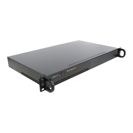
- Page 1 ® UPER 5015A-EHF-D525 UPER ERVER USER’S MANUAL Revision 1.0...
- Page 2 This product, including software and docu- mentation, is the property of Supermicro and/or its licensors, and is supplied only under a license. Any use or reproduction of this product is not allowed, except as expressly permitted by the terms of said license.
-
Page 3: About This Manual
Preface Preface About This Manual This manual is written for professional system integrators and PC technicians. It provides information for the installation and use of the SuperServer 5015A-EHF- D525. Installation and maintainance should be performed by experienced techni- cians only. The SuperServer 5015A-EHF-D525 is a single processor 1U mini rackmount server based on the SC502L-200B server chassis and the Intel®... - Page 4 UPER ERVER 5015A-EHF-D525 User's Manual Chapter 4: System Safety You should thoroughly familiarize yourself with this chapter for a general overview of safety precautions that should be followed when installing and servicing the SuperServer 5015A-EHF-D525. Chapter 5: Advanced Motherboard Setup Chapter 5 provides detailed information on the X7SPE-HF-D525 motherboard, including the locations and functions of connectors, headers and jumpers.
- Page 5 Preface Notes...
-
Page 6: Table Of Contents
System Power ....................1-4 SATA Subsystem ..................... 1-4 Control Panel ....................1-4 Rear I/O Panel ....................1-4 Expansions Cards ................... 1-4 Contacting Supermicro ..................1-5 Chapter 2 Server Installation Overview ......................2-1 Unpacking the System ..................2-1 Preparing for Setup ..................2-1 Choosing a Setup Location ................ - Page 7 Table of Contents HDD ......................... 3-2 Power ......................3-3 Chapter 4 System Safety Electrical Safety Precautions ................4-1 General Safety Precautions ................4-2 ESD Precautions ..................... 4-3 Operating Precautions ..................4-4 Chapter 5 Advanced Motherboard Setup Handling the Motherboard ................5-1 Precautions .....................
- Page 8 UPER ERVER 5015A-EHF-D525 User's Manual SATA DOM Power ..................5-13 Power SMB I C Connector ..............5-13 Serial Ports ....................5-13 SMB ......................5-14 ATX PS/2 Keyboard and PS/2 Mouse Ports ..........5-14 T-SGPIO 0/1 Headers ................5-14 LAN1/2 (Ethernet Ports) ................5-14 Universal Serial Bus (USB) ..............
- Page 9 Table of Contents Main Setup ...................... 7-2 Advanced Setup Confi gurations..............7-4 Security Settings ................... 7-20 Boot Settings ....................7-22 Exit Options ....................7-23 Appendix A POST Error Beep Codes Appendix B System Specifi cations...
- Page 10 UPER ERVER 5015A-EHF-D525 User's Manual Notes...
-
Page 11: Chapter 1 Introduction
Chapter 1 Introduction Overview The Supermicro SuperServer 5015A-EHF-D525 is a single processor, 1U rack- mount server. The 5015A-EHF-D525 is comprised of two main subsystems: the SC502L-200B chassis and the X7SPE-HF-D525 motherboard. Please refer to our web site for information on operating systems that have been certifi ed for use with the 5015A-EHF-D525. -
Page 12: Motherboard Features
UPER ERVER 5015A-EHF-D525 User's Manual Motherboard Features At the heart of the SuperServer 5015A-EHF-D525 is the X7SPE-HF-D525, a single processor, low-power motherboard based upon Intel's ATOM D525 + ICH9R chipset. Below are the main features of the X7SPE-HF-D525. Processor The X7SPE-HF-D525 supports one Intel® Atom™ D525 1.8 GHz processor. The processor is embedded in the motherboard. - Page 13 Chapter 1: Introduction Figure 1-1. Intel Atom D525 + ICH9R Chipset: System Block Diagram Note: This is a general block diagram. Please see Chapter 5 for details.
-
Page 14: Server Chassis Features
UPER ERVER 5015A-EHF-D525 User's Manual Server Chassis Features The following is a general outline of the main features of the SC502L-200B 1U mini rackmount server chassis. System Power The SC502L-200B chassis includes a single 200W power supply. SATA Subsystem The SC502L-200B chassis was designed to support one 3.5" or two 2.5" internal SATA drives (not hot-swappable). -
Page 15: Contacting Supermicro
Super Micro Computer, Inc. 980 Rock Ave. San Jose, CA 95131 U.S.A. Tel: +1 (408) 503-8000 Fax: +1 (408) 503-8008 Email: marketing@supermicro.com (General Information) support@supermicro.com (Technical Support) Web Site: www.supermicro.com Europe Address: Super Micro Computer B.V. Het Sterrenbeeld 28, 5215 ML... - Page 16 UPER ERVER 5015A-EHF-D525 User's Manual Notes...
-
Page 17: Chapter 2 Server Installation
Chapter 2: Server Installation Chapter 2 Server Installation Overview This chapter provides a quick setup checklist to get your SuperServer 5015A-EHF- D525 up and running. Following the steps in the order given should enable you to have the system operational within a minimal amount of time. This quick setup assumes that your 5015A-EHF-D525 system has come to you with the proces- sor and memory preinstalled. - Page 18 UPER ERVER 5015A-EHF-D525 User's Manual • Leave approximately 30 inches of clearance in the back of the rack to allow for suffi cient airfl ow and ease in servicing. • This product is for installation only in a Restricted Access Location (dedicated equipment rooms, service closets, etc.).
-
Page 19: Rack Mounting Considerations
Chapter 2: Server Installation • Always keep the rack's front door and all panels and components on the servers closed when not servicing to maintain proper cooling. Rack Mounting Considerations Ambient Operating Temperature If installed in a closed or multi-unit rack assembly, the ambient operating tempera- ture of the rack environment may be greater than the ambient temperature of the room. -
Page 20: Rack Mounting Instructions
UPER ERVER 5015A-EHF-D525 User's Manual Rack Mounting Instructions This section provides information on installing the SC502 chassis into a rack unit There are a variety of rack units on the market, which may mean the assembly procedure will differ slightly. You should also refer to the installation instructions that came with the rack unit you are using. - Page 21 Chapter 2: Server Installation Installing into a Telco Rack The SC502 supports Telco Rack installation. The SC502 chassis compact design allows the chassis to be installed into a Telco rack without the use of rails. Installing the Chassis into a Telco Rack Confi...
-
Page 22: Checking The Motherboard Setup
UPER ERVER 5015A-EHF-D525 User's Manual Checking the Motherboard Setup After you install the 5015A-EHF-D525 in the rack, you will need to open the unit to make sure the motherboard is properly installed and all the connections have been made. Accessing the Inside of the System (Figure 2-3) First, grasp the two handles on either side and pull the unit straight out until it locks (you will hear a "click"). - Page 23 Chapter 2: Server Installation Figure 2-3. Accessing the Inside of the System...
-
Page 24: Checking The Drive Bay Setup
UPER ERVER 5015A-EHF-D525 User's Manual Checking the Drive Bay Setup Next, you should check to make sure the drives have been properly installed and all essential connections have been made. Checking the Drives Depending upon your system's confi guration, your system may have one or two SATA drives already installed. -
Page 25: Chapter 3 System Interface
Chapter 3: System Interface Chapter 3 System Interface Overview There are several LEDs on the control panel to keep you constantly informed of the overall status of the system as well as the activity and health of specifi c components. There are also two buttons on the control panel. -
Page 26: Overheat
UPER ERVER 5015A-EHF-D525 User's Manual Overheat When this LED is on it indicates an overheat condition, which may be caused by cables obstructing the airfl ow in the system or the ambient room temperature being too warm. Check the routing of the cables and make sure all fans are present and operating normally. -
Page 27: Power
Chapter 3: System Interface Power Indicates power is being supplied to the system's power supply units. This LED should normally be illuminated when the system is operating. - Page 28 UPER ERVER 5015A-EHF-D525 User's Manual Notes...
-
Page 29: Chapter 4 System Safety
Chapter 4: System Safety Chapter 4 System Safety Electrical Safety Precautions Basic electrical safety precautions should be followed to protect yourself from harm and the SuperServer 5015A-EHF-D525 from damage: • Be aware of the locations of the power on/off switch on the chassis as well as the room's emergency power-off switch, disconnection switch or electrical outlet. -
Page 30: General Safety Precautions
UPER ERVER 5015A-EHF-D525 User's Manual • Motherboard Battery: CAUTION - There is a danger of explosion if the onboard battery is installed upside down, which will reverse its polarites (see Figure 4-1). This battery must be replaced only with the same or an equivalent type recom- mended by the manufacturer (CR2032). -
Page 31: Esd Precautions
Chapter 4: System Safety ESD Precautions Electrostatic Discharge (ESD) is generated by two objects with different electrical charges coming into contact with each other. An electrical discharge is created to neutralize this difference, which can damage electronic com ponents and printed circuit boards. -
Page 32: Operating Precautions
UPER ERVER 5015A-EHF-D525 User's Manual Operating Precautions Care must be taken to assure that the chassis cover is in place when the 5015A- EHF-D525 is operating to assure proper cooling. Out of warranty damage to the system can occur if this practice is not strictly followed. Figure 4-1. -
Page 33: Chapter 5 Advanced Motherboard Setup
Chapter 5: Advanced Motherboard Setup Chapter 5 Advanced Motherboard Setup This chapter covers the steps required to install the X7SPE-HF-D525 motherboard into the chassis, connect the data and power cables and install add-on cards. All motherboard jumpers and connections are also described. A layout and quick refer- ence chart are included in this chapter for your reference. -
Page 34: Unpacking
UPER ERVER 5015A-EHF-D525 User's Manual Unpacking The motherboard is shipped in antistatic packaging to avoid electrical static dis- charge. When unpacking the board, make sure the person handling it is static protected. Motherboard Installation This section explains the fi rst step of physically mounting the X7SPE-HF-D525 into the SC502L-200B chassis. -
Page 35: Connecting Cables
Chapter 5: Advanced Motherboard Setup Connecting Cables Now that the motherboard is installed, the next step is to connect the cables to the board. These include the data cables for the peripherals and control panel and the power cables. Connecting Data Cables The cables used to transfer data from the peripheral devices have been carefully routed to prevent them from blocking the fl... -
Page 36: I/O Ports
UPER ERVER 5015A-EHF-D525 User's Manual Figure 5-1. Control Panel Header Pins Ground Power LED HDD LED NIC1 LED NIC2 LED OH/Fan Fail LED Power Fail LED Reset Reset Button Ground Power Button Ground I/O Ports The I/O ports are color coded in conformance with the PC 99 specifi cation. See Figure 5-2 below for the colors and locations of the various I/O ports. -
Page 37: Onboard Processor
A small active heatsink sits on the proces- sor to keep it cool. 5-6 Installing Memory Note: Check the Supermicro web site for recommended memory modules. CAUTION Exercise extreme care when installing or removing DIMM modules to prevent any possible damage. - Page 38 UPER ERVER 5015A-EHF-D525 User's Manual Figure 5-3. DIMM Installation Position the SO-DIMM mod- Align ule's bottom key so that it aligns with the receptive point on the slot. Insert the SO-DIMM module vertically at about a 45 degree angle. Press down until the module locks into place.
-
Page 39: Adding Pci Expansion Cards
Chapter 5: Advanced Motherboard Setup Adding PCI Expansion Cards The SC502L-200B chassis can accommodate one full-height, half-length PCI- Express expansion card (a PCI-E x4 card in a x16 slot). Installing an Expansion Card After powering down the system, remove the PCI slot shield. Fully seat the card into the slot, pushing down with your thumbs evenly on both sides of the card. -
Page 40: Motherboard Details
UPER ERVER 5015A-EHF-D525 User's Manual Motherboard Details Figure 5-4. X7SPE-HF-D525 Layout Note: Jumpers not indicated are for test purposes only. Number Jumper Description Default Setting 12, 11 C1/JI SMB to PCI Slots Open/Open (Disabled) JPL2 LAN2 Enable/Disable Pins 1-2 (Enabled) JPL1 LAN1 Enable/Disable Pins 1-2 (Enabled) - Page 41 Chapter 5: Advanced Motherboard Setup Number Connector Description KB/Mouse PS/2 Keyboard/Mouse 2, 3 USB1/2 Back Panel USB Ports COM1 Back Panel Serial Port Video/Graphics Port LAN1 RJ45 Connector for LAN1 LAN2 RJ45 Connector for LAN2 Chassis Intrusion Header JBAT1 Onboard Battery JPCIE1 PCI-E 1.1 x4 Gen1 (in x16 physical) Slot 20, 21, 23...
-
Page 42: Connector Defi Nitions
UPER ERVER 5015A-EHF-D525 User's Manual Connector Defi nitions ATX Power 24-pin Connector Pin Defi nitions Pin# Defi nition Pin # Defi nition Main ATX Power Supply +3.3V +3.3V Connector -12V +3.3V The 24-pin main power connector (JPW1) is used to provide power to PS_ON the motherboard. -
Page 43: Reset Button
Chapter 5: Advanced Motherboard Setup Reset Button Reset Button Pin Defi nitions (JF1) The reset button (from the computer Pin# Defi nition chassis) connects to pins 3 and 4 of Reset JF1. See the table on the right for pin Ground defi... -
Page 44: Power Led
UPER ERVER 5015A-EHF-D525 User's Manual Power LED The Power LED connector is located Power LED Pin Defi nitions (JF1) on pins 15 and 16 of JF1. This con- Pin# Defi nition nection is used to provide LED indica- 5V Stby tion of power being supplied to the Control system. -
Page 45: Chassis Intrusion
Chapter 5: Advanced Motherboard Setup Chassis Intrusion Chassis Intrusion A Chassis Intrusion header is located Pin Defi nitions (JL1) at JL1 on the motherboard. Attach the Pin# Defi nition appropriate cable from the chassis to Intrusion Input inform you of a chassis intrusion when Ground the chassis is opened. -
Page 46: Smb
UPER ERVER 5015A-EHF-D525 User's Manual SMB Header Pin Defi nition A System Management Bus (SMB) Pin# Defi nition header is located at JSMB. Connect Data the appropriate cable here to use Ground the SMB I C connection on your Clock system. -
Page 47: Universal Serial Bus (Usb)
Chapter 5: Advanced Motherboard Setup Back Panel USB Ports, Type A USB Port Pin Defi nitions Pin# Defi nition Pin# Defi nition Universal Serial Bus (USB) Four Universal Serial Bus ports USB_PN USB_PN (USB1/2/3/4) are located on the I/O USB_PP USB_PP backpanel. -
Page 48: 5-10 Jumper Settings
UPER ERVER 5015A-EHF-D525 User's Manual 5-10 Jumper Settings Explanation of Jumpers To modify the operation of the mother- board, jumpers can be used to choose Connector between optional settings. Jumpers Pins create shorts between two pins to change the function of the connector. Pin 1 is identifi... -
Page 49: Smb (I 2 C) Bus To Pci Slots
Chapter 5: Advanced Motherboard Setup SMB (I C) Bus to PCI Slots C to PCI-Slots Jumpers JI C1 and JI C2 allow you Jumper Settings to connect the System Management Jumper Defi nition Bus (SMB) to the PCI-E PCI slot. The Enabled default setting is Disabled. -
Page 50: Dcd / P5V Select (Oem Option)
UPER ERVER 5015A-EHF-D525 User's Manual DCD / P5V Select (OEM option) Jumpers J10~J13 allow selection DCD / P5V Select Jumper Settings between the standard Data Carrier Jumper Setting Defi nition Detect (DCD) modem signal or the Pins 1-2 system voltage +5V on pin 1 of the Pins 2-3 COM1~COM4 ports This is an OEM option only. -
Page 51: 5-11 Onboard Indicators
Chapter 5: Advanced Motherboard Setup 5-11 Onboard Indicators LAN1/2 LED (Connection Speed Indicator) LED Color Defi nition LAN1/2 LEDs No Connection or 10 Mb/s The Ethernet ports (located beside the Green 100 Mb/s VGA port) have two LEDs. On each Amber 1 Gb/s port, the yellow LED indicates activity... -
Page 52: 5-13 Installing Software
5-13 Installing Software After the hardware has been installed, you should fi rst install the operating system and then the drivers. The necessary drivers are all included on the Supermicro CDs that came packaged with your motherboard. Driver/Tool Installation Display Screen (example shown) Note: Click the icons showing a hand writing on paper to view the readme fi... -
Page 53: Supero Doctor Iii
Chapter 5: Advanced Motherboard Setup Supero Doctor III The Supero Doctor III program is a web-based management tool that supports remote management capability. It includes Remote and Local Management tools. The local management is called SD III Client. The Supero Doctor III program in- cluded on the CD-ROM that came with your motherboard allows you to monitor the environment and operations of your system. - Page 54 Supero Doctor III Interface Display Screen (Remote Control) Note: SD III Software Revision 1.0 can be downloaded from our Web Site at: ftp://ftp. supermicro.com/utility/Supero_Doctor_III/. You can also download the SDIII User's Guide at: <http://www.supermicro.com/manuals/other/SDIII_User_Guide.pdf>. For Linux, we will recommend using Supero Doctor II.
-
Page 55: Chapter 6 Advanced Chassis Setup
Chapter 6: Advanced Chassis Setup Chapter 6 Advanced Chassis Setup This chapter covers the steps required to install components and perform main- tenance on the SC502L chassis. For component installation, follow the steps in the order given to eliminate the most common problems encountered. If a step is unnecessary, skip ahead to the step that follows. -
Page 56: Control Panel
UPER ERVER 5015A-EHF-D525 User's Manual Figure 6-1. Chassis Front View Control Panel Figure 6-2. Chassis Rear View Power Supply Mouse/Keyboard Ethernet Ports PCI Slot USB Ports COM Port VGA Port Control Panel The control panel (located on the front of the chassis) must be connected to the JF1 connector on the serverboard to provide you with system control buttons and status indicators. -
Page 57: System Fans
Use screws to secure the bracket/drive assembly into the left side of the chassis as shown in the fi gure. Enterprise level hard disk drives are recommended for use in Supermicro chassis and servers. For information on recommended HDDs, visit the... - Page 58 UPER ERVER 5015A-EHF-D525 User's Manual The 3.5" hard drive screws directly into the chassis Figure 6-3. Installing a 3.5" Hard Drive The 2.5" hard drives (1) must be installed in the (optional) bracket (2) before they are screwed into the chassis. Figure 6-4.
-
Page 59: Power Supply
In the event that the power supply unit fails, the system will shut down and you will need to change the power supply unit. New units can be ordered directly from Supermicro (see contact information in the Preface). Replacing the Power Supply (Figure 6-5) Power down the system and unplug the AC power cord. - Page 60 UPER ERVER 5015A-EHF-D525 User's Manual Rear Mounting Screws Power Supply Mounting Thru Holes Bottom Mounting Screws Figure 6-5. Installing the Power Supply...
-
Page 61: Chapter 7 Bios
When an option is selected in the left frame, it is highlighted in white. Often a text message will accompany it. (Note: the AMI BIOS has default text messages built in. Supermicro retains the option to include, omit, or change any of these text messages.) The AMI BIOS Setup Utility uses a key-based navigation system called "hot keys". -
Page 62: How To Start The Setup Utility
Warning! Do not upgrade the BIOS unless your system has a BIOS-related issue. Flashing the wrong BIOS can cause irreparable damage to the system. In no event shall Supermicro be liable for direct, indirect, special, incidental, or consequential damages arising from a BIOS update. If you have to update the BIOS, do not shut down or reset the system while the BIOS is updating. - Page 63 <Tab> key or the arrow keys to move between fi elds. The date must be entered in Day MM/DD/YY format. The time is entered in HH:MM:SS format. (Note: The time is in the 24-hour format. For example, 5:30 P.M. appears as 17:30:00.) Supermicro X7SPA-L/X7SPA-H/X7SPA-HF Version Build Date...
-
Page 64: Advanced Setup Confi Gurations
UPER ERVER 5015A-EHF-D525 User's Manual Advanced Setup Confi gurations Use the arrow keys to select Boot Setup and hit <Enter> to access the submenu items: BOOT Feature Quick Boot If Enabled, this option will skip certain tests during POST to reduce the time needed for system boot. - Page 65 Chapter 7: BIOS Bootup Num-Lock This feature selects the Power-on state for Numlock key. The options are Off and On. PS/2 Mouse Support This feature enables support for the PS/2 mouse. The options are Disabled, Enabled and Auto. Wait For 'F1' If Error This forces the system to wait until the 'F1' key is pressed if an error occurs.
- Page 66 UPER ERVER 5015A-EHF-D525 User's Manual Standby Power in S5 This feature supplies standby power while in S5 (sleep mode). Set this feature to Disabled to comply with EuP requirements, Enable this feature to activate wake-up capability while in sleep mode. The options are Enabled and Disabled. CPU Confi...
- Page 67 Chapter 7: BIOS Advanced Chipset Control The items included in the Advanced Settings submenu are listed below. Northbridge Confi guration DRAM Frequency This option allows the user to select the desired frequency setting for the onboard memory modules. The options are Auto, 667 MHz and 800 MHz. Confi...
- Page 68 UPER ERVER 5015A-EHF-D525 User's Manual Active State Power Management Select Enabled to start Active-State Power Management for signal transactions between L0 and L1 Links on the PCI Express Bus. This maximizes power-saving and transaction speed. The options are Enabled and Disabled. Reserved Page Route This feature allows the user to decide which bus to send debug information to.
- Page 69 Chapter 7: BIOS SATA#2 Confi guration (Available if IDE is enabled under "Confi gure SATA#1 as" above) Selecting Enhanced will set SATA#2 to native SATA mode. The options are Dis- abled and Enhanced IDE Detect Timeout (sec) Use this feature to set the time-out value for the BIOS to detect the ATA, ATAPI devices installed in the system.
- Page 70 UPER ERVER 5015A-EHF-D525 User's Manual Select Auto to allow the AMI BIOS to automatically detect the PIO mode. Use this value if the IDE disk drive support cannot be determined. Select 0 to allow the AMI BIOS to use PIO mode 0. It has a data transfer rate of 3.3 MBs.
- Page 71 Chapter 7: BIOS Select UDMA4 to allow the BIOS to use Ultra DMA mode 4 . It has a data transfer rate of 100 MBs. The options are Auto, SWDMAn, MWDMAn, and UDMAn. S.M.A.R.T. For Hard disk drives Self-Monitoring Analysis and Reporting Technology (SMART) can help predict impending drive failures.
- Page 72 UPER ERVER 5015A-EHF-D525 User's Manual PCI Slot 1 Use this feature to enable or disable PCI slot Option ROMs. The options are Dis- abled and Enabled. Load Onboard LAN 1 Option ROM/ Load Onboard LAN 2 Option ROM Select Enabled to load the onboard LAN Option ROM for the LAN port as specifi ed. The options are Enabled and Disabled.
- Page 73 Chapter 7: BIOS Flow Control This feature allows the user to set the fl ow control for Console Redirection. The options are None, Hardware, and Software. Redirection After BIOS POST Select Disabled to turn off Console Redirection after Power-On Self-Test (POST).
- Page 74 UPER ERVER 5015A-EHF-D525 User's Manual Hardware Health Confi guration This feature allows the user to monitor Hardware Health of the system and review the status of each item when displayed. CPU Overheat Alarm This option allows the user to select the CPU Overheat Alarm setting which de- termines when the CPU OH alarm will be activated to provide warning of possible CPU overheat.
- Page 75 Tolerances’, the installed CPU can now send its ‘Temperature Toler- ance’ to the motherboard resulting in better CPU thermal management. Supermicro has leveraged this feature by assigning a temperature status to certain thermal conditions in the processor (Low, Medium and High). This makes it easier for the user to understand the CPU’s temperature status,...
- Page 76 UPER ERVER 5015A-EHF-D525 User's Manual Fan Speed Control Modes This feature allows the user to decide how the system controls the speeds of the onboard fans. The CPU temperature and the fan speed are correlative. When the CPU on-die temperature increases, the fan speed will also increase for effective system cooling.
- Page 77 Chapter 7: BIOS ACPI Aware O/S Enable ACPI support if it is supported by the OS to control ACPI through the Operat- ing System. Otherwise, disable this feature. The options are Yes and No. Suspend Mode This setting allows you to confi gure the ACPI (Advanced Confi guration and Power Interface) state for your system when it is in the Suspend mode.
- Page 78 UPER ERVER 5015A-EHF-D525 User's Manual IPMI Confi guration Intelligent Platform Management Interface (IPMI) is a set of common interfaces that IT administrators can use to monitor system health and to manage the system as a whole. For more information on the IPMI specifi cations, please visit Intel's website at www.intel.com.
- Page 79 Chapter 7: BIOS IP Address - Enter the IP address for this machine. This should be in decimal and in dotted quad form (i.e., 192.168.10.253). The value of each three-digit number separated by dots should not exceed 255. Subnet Mask - Subnet masks tell the network which subnet this machine belongs to.
-
Page 80: Security Settings
UPER ERVER 5015A-EHF-D525 User's Manual Security Settings The AMI BIOS provides a Supervisor and a User password. If you use both pass- words, the Supervisor password must be set fi rst. Supervisor Password This item indicates if a supervisor password has been entered for the system. Clear means such a password has not been used and Set means a supervisor password has been entered for the system. - Page 81 Chapter 7: BIOS Change User Password Select this feature and press <Enter> to access the submenu , and then type in a new User Password. Clear User Password (Available only if User Password has been set) Password Check Available options are Setup and Always. Boot Sector Virus Protection When Enabled, the AMI BOIS displays a warning when any program (or virus) is- sues a Disk Format command or attempts to write to the boot sector of the hard...
-
Page 82: Boot Settings
UPER ERVER 5015A-EHF-D525 User's Manual Boot Settings Use this feature to confi gure Boot Settings: Boot Device Priority This feature allows the user to specify the sequence of priority for the Boot Device. The settings are 1st boot device, 2nd boot device, 3rd boot device, 4th boot device, 5th boot device and Disabled. -
Page 83: Exit Options
Chapter 7: BIOS Removable Drives This feature allows the user to specify the boot sequence from available Removable Drives. The settings are 1st boot device, 2nd boot device, and Disabled. • 1st Drive • 2nd Drive - [USB: XXXXXXXXX] Retry Boot Devices Select this option to retry booting from the confi... - Page 84 UPER ERVER 5015A-EHF-D525 User's Manual fi guration parameters can take effect. Select Save Changes and Exit from the Exit menu and press <Enter>. Discard Changes and Exit Select this option to quit the BIOS Setup without making any permanent changes to the system confi...
-
Page 85: Appendix A Post Error Beep Codes
Appendix A: POST Error Beep Codes Appendix A POST Error Beep Codes This section lists POST (Power On Self Test) error beep codes for the AMI BIOS. POST error beep codes are divided into two categories: recoverable and terminal. This section lists Beep Codes for recoverable POST errors. Recoverable POST Error Beep Codes When a recoverable type of error occurs during POST, BIOS will display a POST code that describes the problem. - Page 86 UPER ERVER 5015A-EHF-D525 User's Manual Notes...
-
Page 87: Appendix B System Specifi Cations
Appendix B: System Specifi cations Appendix B System Specifi cations Processors Embedded single Intel® Atom™ D525 dual-core 1.8 GHz processor Chipset Intel Atom D525 + ICH9R chipset BIOS 8 Mb Flash EEPROM with AMI BIOS Memory Capacity Two DIMM slots that can support up to 4 GB of unbuffered non-ECC DDR3- 800 SO-DIMM memory Note: See the memory section in Chapter 5 for details. - Page 88 UPER ERVER 5015A-EHF-D525 User's Manual System Input Requirements AC Input Voltage: 100-240 VAC (auto-range) Rated Input Current: 3A max. Rated Input Frequency: 50 to 60 Hz Power Supply Rated Output Power: 200W (Part# PWS-202-1H) Rated Output Voltages: +3.3V (8A), +5V (8A), +12V (16A), -12V (0.5A), +5Vsb (2A) Operating Environment Operating Temperature: 10º...
- Page 89 Appendix B: System Specifi cations Notes...
- Page 90 ERVER 5015A-EHF-D525 User's Manual (continued from front) The products sold by Supermicro are not intended for and will not be used in life support systems, medical equipment, nuclear facilities or systems, aircraft, aircraft devices, aircraft/emergency com- munication devices or other critical systems whose failure to perform be reasonably expected to result in signifi...
Need help?
Do you have a question about the Supero SUPERSERVER 5015A-EHF-D525 and is the answer not in the manual?
Questions and answers