
Related Manuals for Supero SuperServer 5016I-MT


Summary of Contents for Supero SuperServer 5016I-MT
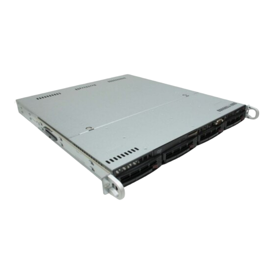
- Page 1 UPER ® 5016I-MT uper erver 5016I-MTF uper erver USER’S MANUAL Revision 1.0...
- Page 2 The information in this User’s Manual has been carefully reviewed and is believed to be accurate. The vendor assumes no responsibility for any inaccuracies that may be contained in this document, makes no commitment to update or to keep current the information in this manual, or to notify any person or organization of the updates.
-
Page 3: About This Manual
Preface About This Manual This manual is written for professional system integrators and PC technicians. It provides information for the installation and use of the SuperServer 5016I-MT/5016I- MTF. Installation and maintenance shall be performed by experienced technicians only. The SuperServer 5016I-MT/5016I-MTF is a single processor system based on the SC813MTQ-350 1U rackmount chassis and the Super X8SIE/X8SIE-F moth- erboard. - Page 4 UPER ERVER 5016I-MT/5016I-MTF User's Manual Chapter 5: Advanced Motherboard Setup Chapter 5 provides detailed information on the X8SIE/X8SIE-F motherboard, including the locations and functions of connectors, headers and jumpers. Refer to this chapter when adding or removing processors or main memory and when reconfi...
- Page 5 Preface Notes...
-
Page 6: Table Of Contents
UPER ERVER 5016I-MT/5016I-MTF User's Manual Table of Contents Chapter 1 Introduction Overview ......................1-1 Motherboard Features ..................1-2 Processors ...................... 1-2 Memory ......................1-2 Serial ATA ....................... 1-2 PCI Expansion Slots ..................1-2 I/O Ports ......................1-2 Other Features ....................1-2 Chassis Features .................... - Page 7 Table of Contents Chapter 3 System Interface Overview ......................3-1 Control Panel Buttons ..................3-1 Reset ....................... 3-1 Power ......................3-1 Control Panel LEDs ..................3-2 Overheat/Fan Fail ................... 3-2 NIC2 ........................ 3-2 NIC1 ........................ 3-2 HDD ......................... 3-2 Power ......................3-3 Drive Carrier LEDs ..................
- Page 8 UPER ERVER 5016I-MT/5016I-MTF User's Manual Processor Power Connector ..............5-15 Power Button ................... 5-15 Reset Button ................... 5-15 Overheat (OH)/Fan Fail/Front UID LED ........... 5-16 NIC1/NIC2 (LAN1/LAN2) ................5-16 HDD LED ....................5-16 Power On LED ..................5-16 Chassis Intrusion ..................5-17 ATX PS/2 Keyboard and PS/2 Mouse Ports ..........
- Page 9 Table of Contents 5-13 Installing Additional Drivers ................5-25 5-14 Confi guring Supero Doctor III ............... 5-26 Chapter 6 Advanced Chassis Setup Static-Sensitive Devices .................. 6-1 Precautions ..................... 6-1 Unpacking ....................... 6-1 Control Panel ....................6-2 System Fans ....................6-3 Drive Bay Installation/Removal ...............
- Page 10 UPER ERVER 5016I-MT/5016I-MTF User's Manual Notes...
-
Page 11: Chapter 1 Introduction
Chapter 1 Introduction Overview The SuperServer 5016I-MT/5016I-MTF is a high-end server comprised of two main subsystems: the SC813MTQ-350 1U chassis and the X8SIE/X8SIE-F motherboard. Please refer to our web site for information on operating systems that have been cer- tifi ed for use with the SuperServer 5016I-MT/5016I-MTF (www.supermicro.com). -
Page 12: Motherboard Features
ERVER 5016I-MT/5016I-MTF User's Manual Motherboard Features At the heart of the SuperServer 5016I-MT/5016I-MTF lies the X8SIE/X8SIE-F, a single processor motherboard based on the Intel® 3420 chipset. Below are the main features of the X8SIE/X8SIE-F. See Figure 1-1 for a block diagram of the chipset. -
Page 13: Chassis Features
Chapter 1: Introduction Chassis Features System Power When confi gured as a SuperServer 5016I-MT/5016I-MTF, the SC813MTQ-350 chassis includes a single 350W power supply. SATA Subsystem The SC813MTQ-350 chassis was designed to support four SATA hard drives, which are hot-swappable units. -
Page 14: System Block Diagram
UPER ERVER 5016I-MT/5016I-MTF User's Manual Figure 1-1. Intel 3420 Chipset: System Block Diagram Note: This is a general block diagram. Please see Chapter 5 for details. DDR3 (CHA) DIMM1(Far) DIMM2 1333/1066MHz Intel® DIMM3 4 UDIMM PCIe2.0_x16 Xeon® 3400 PCIe x16 SLOT Series 5.0GT/s 6 RDIMM... -
Page 15: Contacting Supermicro
Chapter 1: Introduction Contacting Supermicro Headquarters Address: Super Micro Computer, Inc. 980 Rock Ave. San Jose, CA 95131 U.S.A. Tel: +1 (408) 503-8000 Fax: +1 (408) 503-8008 Email: marketing@supermicro.com (General Information) support@supermicro.com (Technical Support) Web Site: www.supermicro.com Europe Address: Super Micro Computer B.V. Het Sterrenbeeld 28, 5215 ML 's-Hertogenbosch, The Netherlands Tel:... - Page 16 UPER ERVER 5016I-MT/5016I-MTF User's Manual Notes...
-
Page 17: Chapter 2 Server Installation
Server Precautions in the next section. Preparing for Setup The box the SuperServer 5016I-MT/5016I-MTF was shipped in should include two sets of rail assemblies, six rail mounting brackets and the mounting screws you will need to install the system into the rack. Follow the steps in the order given to complete the installation process in a minimal amount of time. -
Page 18: Rack Precautions
UPER ERVER 5016I-MT/5016I-MTF User's Manual installation only in a Restricted Access Location (dedicated equipment rooms, service closets and the like). • This product is not suitable for use with visual display work place devices acccording to §2 of the the German Ordinance for Work with Visual Display Units. -
Page 19: Rack Mounting Considerations
Chapter 2: Server Installation Rack Mounting Considerations Ambient Operating Temperature If installed in a closed or multi-unit rack assembly, the ambient operating tempera- ture of the rack environment may be greater than the ambient temperature of the room. Therefore, consideration should be given to installing the equipment in an environment compatible with the manufacturer’s maximum rated ambient tempera- ture (Tmra). -
Page 20: Installing The System Into A Rack
Identifying the Sections of the Rack Rails You may have received rack rail hardware with the SuperServer 5016I-MT/5016I- MTF. (Two front inner rails should already be attached to the chassis.) This hard- ware consists of two rear inner rails that secure to the chassis, one on each side just behind the preinstalled front inner rails. -
Page 21: Installing The Rack Rails
Figure 2-1. Installing Rear Inner Chassis Rails Installing the Rack Rails Determine where you want to place the SuperServer 5016I-MT/5016I-MTF in the rack (see Rack and Server Precautions in Section 2-3). Position the chassis rail guides at the desired location in the rack, keeping the sliding rail guide facing the inside of the rack. -
Page 22: Installing The Server Into The Rack
UPER ERVER 5016I-MT/5016I-MTF User's Manual Installing the Server into the Rack You should now have rails attached to both the chassis and the rack unit. The next step is to install the server into the rack. Do this by lining up the rear of the chassis rails with the front of the rack rails. -
Page 23: Installing The Server Into A Telco Rack
Chapter 2: Server Installation Installing the Server into a Telco Rack To install the SuperServer 5016I-MT/5016I-MTF into a Telco type rack, use two L- shaped brackets on either side of the chassis (four total). First, determine how far the server will extend out the front of the rack. Larger chassis should be positioned to balance the weight between front and back. -
Page 24: Checking The Motherboard Setup
UPER ERVER 5016I-MT/5016I-MTF User's Manual Checking the Motherboard Setup After you install the 5016I-MT/5016I-MTF in the rack, you will need to open the unit to make sure the motherboard is properly installed and all the connections have been made. Accessing the Inside of the System Grasp the two handles on either side and pull the unit straight out until it locks (you will hear a "click"). -
Page 25: Checking The Drive Bay Setup
Chapter 2: Server Installation Figure 2-4. Accessing the Inside of the SuperServer 5016T-MTFB Checking the Drive Bay Setup Next, you should check to make sure the peripheral drives and the SATA drives and their backplane have been properly installed and all essential connections have been made. - Page 26 UPER ERVER 5016I-MT/5016I-MTF User's Manual Also note that all power and data cables have been routed in such a way that they do not block the airfl ow generated by the fans. Providing Power Plug the power cord from the power supply unit into a high-quality power strip that offers protection from electrical noise and power surges.
-
Page 27: Chapter 3 System Interface
Chapter 3: System Interface Chapter 3 System Interface Overview There are several LEDs on the control panel as well as others on the SATA drive carriers to keep you constantly informed of the overall status of the system as well as the activity and health of specifi... -
Page 28: Control Panel Leds
UPER ERVER 5016I-MT/5016I-MTF User's Manual Control Panel LEDs The control panel located on the front of the SC813MTQ-350 chassis has fi ve LEDs. These LEDs provide you with critical information related to different parts of the system. This section explains what each LED indicates when illuminated and any corrective action you may need to take. -
Page 29: Power
Chapter 3: System Interface Power Indicates power is being supplied to the system's power supply units. This LED should normally be illuminated when the system is operating. Drive Carrier LEDs Each drive carrier has two LEDs. • Green: When illuminated, the green LED on the front of the drive carrier in- dicates drive activity. - Page 30 UPER ERVER 5016I-MT/5016I-MTF User's Manual Notes...
-
Page 31: Chapter 4 System Safety
Basic electrical safety precautions shall be followed to protect yourself from harm and the SuperServer 5016I-MT/5016I-MTF from damage: • Be aware of the locations of the power on/off switch on the chassis as well as the room's emergency power-off switch, disconnection switch or electrical outlet. -
Page 32: General Safety Precautions
Contact technical support for details and support. General Safety Precautions Follow these rules to ensure general safety: • Keep the area around the SuperServer 5016I-MT/5016I-MTF clean and free of clutter. • The SuperServer 5016I-MT/5016I-MTF weighs approximately 38 lbs. (17.3 kg) when fully loaded. -
Page 33: Esd Precautions
Chapter 4: System Safety • Remove any jewelry or metal objects from your body, which are excellent metal conductors that can create short circuits and harm you if they come into contact with printed circuit boards or areas where power is present. •... -
Page 34: Operating Precautions
UPER ERVER 5016I-MT/5016I-MTF User's Manual Operating Precautions Care must be taken to assure that the chassis cover is in place when the 5016I- MT/5016I-MTF is operating to assure proper cooling. Out of warranty damage to the system can occur if this practice is not strictly followed. Figure 4-1. -
Page 35: Chapter 5 Advanced Motherboard Setup
Chapter 5: Advanced Motherboard Setup Chapter 5 Advanced Motherboard Setup This chapter covers the steps required to install the X8SIE/X8SIE-F motherboard into the chassis, connect the data and power cables and install add-on cards. All jumpers and connections are described and a layout and quick reference chart are included for your reference. -
Page 36: Motherboard Installation
UPER ERVER 5016I-MT/5016I-MTF User's Manual Motherboard Installation This section explains the fi rst step of physically mounting the X8SIE/X8SIE-F into the SC813MTQ-350 chassis. Following the steps in the order given will eliminate the most common problems encountered in such an installation. To remove the motherboard, follow the procedure in reverse order. -
Page 37: Connecting Power Cables
Chapter 5: Advanced Motherboard Setup cables (with their locations noted) should be connected. (See the layout on page 5-9 for connector locations.) • SATA drive data cable (I-SATA0 ~ I-SATA3) • Control Panel cable (JF1) • COM Port cable (COM2) •... -
Page 38: I/O Ports
UPER ERVER 5016I-MT/5016I-MTF User's Manual I/O Ports The I/O ports are color coded in conformance with the PC 99 specifi cation. See Figure 5-2 below for the colors and locations of the various I/O ports. Figure 5-2. I/O Ports 1. Keyboard (Purple) 6. -
Page 39: Installing The Lga1156 Processor
Chapter 5: Advanced Motherboard Setup Installing the LGA1156 Processor Press the load lever to release the load plate, which covers the CPU socket, from its locked position. Gently lift the load lever to open the load plate. Remove the plate cap. Use your thumb and your index fi... - Page 40 UPER ERVER 5016I-MT/5016I-MTF User's Manual Align the CPU key that is the semi-circle cutouts against the socket keys. Once aligned, carefully lower the CPU straight down to the socket. (Do not drop the CPU on the socket. Do not move the CPU horizontally or vertically. Do not rub the CPU against the surface or against any pins of the socket to avoid damage to the CPU or the socket.) With the CPU inside the socket, inspect the four corners of the CPU to make...
-
Page 41: Installing A Passive Cpu Heatsink
Chapter 5: Advanced Motherboard Setup Installing a Passive CPU Heatsink Do not apply any thermal grease to the heatsink or the CPU die -- the re- quired amount has already been applied. Place the heatsink on top of the CPU so that the four mounting holes are aligned with those on the motherboard and the heatsink bracket underneath. - Page 42 UPER ERVER 5016I-MT/5016I-MTF User's Manual Removing the Heatsink Warning: We do not recommend removing the CPU or the heatsink. How- ever, if you do need to remove the heatsink, please follow the instructions below to prevent damage to the CPU or other components. Unscrew the heatsink screws from the motherboard in the sequence as shown in the illustration below.
-
Page 43: Installing Memory
Chapter 5: Advanced Motherboard Setup Installing Memory Note: Check the Supermicro web site for recommended memory modules. CAUTION Exercise extreme care when installing or removing DIMM modules to prevent any possible damage. DIMM Installation Insert the desired number of DIMMs into the memory slots, starting with DIMM1A. -
Page 44: Memory Population Guidelines
UPER ERVER 5016I-MT/5016I-MTF User's Manual Table 2 - DDR3 ECC Registered (RDIMM) Memory Support RDIMM 1Gb (x8 DRAM) 2Gb (x8 DRAM) Single Rank Up to 6GB Up to 12GB (6 x 1GB DIMM Modules) (6 x 2GB DIMM Modules) Dual Rank Up to 12GB Up to 24GB (6 x 2GB DIMM Modules) -
Page 45: Installing A Pci Expansion Card
Chapter 5: Advanced Motherboard Setup DDR3 ECC RDIMM Memory DIMM Slots DIMMs DIMM Type POR Speeds Ranks per DIMM per Channel Populated (any combination) per Channel Registered 1066, 1333 Single Rank, Dual DDR3 ECC Rank Registered 1066 Quad Rank DDR3 ECC Registered 1066, 1333 Single Rank, Dual... -
Page 46: Motherboard Details
UPER ERVER 5016I-MT/5016I-MTF User's Manual Motherboard Details Figure 5-6. X8SIE/X8SIE-F Layout KB/MOUSE JPUSB1:B/P USB WAKE UP JPI2C:PWR I2C 1-2:ENABLE 2-3:DISABLE FLOPPY JPUSB1 JAR: PSU ALARM RST DDR3 1066/1333 UDIMM/RDIMM required FAN5 LAN1/LAN3 JPL1:LAN1 1-2:ENABLE 2-3:DISABLE JPL2:LAN2 1-2:ENABLE LAN2/LAN4 2-3:DISABLE JPL3:LAN3 1-2:ENABLE 2-3:DISABLE JPL4:LAN4... - Page 47 Chapter 5: Advanced Motherboard Setup Headers & Connectors Number Connector Description COM1 COM1 Serial Port (Backpanel) COM2 COM2 Header Connector 38, 37, 32, Fans 1~5 System/CPU Fan Headers (CPU Fan: Fan 1, #38) 28, 7 Floppy Floppy Disk Drive Connector Alarm Reset Front Panel Control header Chassis Intrusion header...
- Page 48 UPER ERVER 5016I-MT/5016I-MTF User's Manual Jumpers Jumper Description Default Number JPUSB1 USB0/1 Wake-up Pins 1-2 (Enabled) JBT1 CMOS Clear (See Section 5-10 JPS1 SAS Enable Pins 1-2 (Enabled) C1/JI SMB to PCI Slots (See Section 5-10 JPG1 Onboard VGA Enable Pins 1-2 (Enabled) JPL1/JPL2 LAN1/LAN2 Enable...
-
Page 49: Connector Defi Nitions
Chapter 5: Advanced Motherboard Setup Connector Defi nitions ATX Power 24-pin Connector Pin Defi nitions Pin# Defi nition Pin # Defi nition Main ATX Power Supply +3.3V +3.3V Connector -12V +3.3V The primary power supply connec- tor (JPW1) meets the SSI EPS 12V PS_ON specifi... -
Page 50: Overheat (Oh)/Fan Fail/Front Uid Led
UPER ERVER 5016I-MT/5016I-MTF User's Manual Overheat (OH)/Fan Fail/Front UID OH/Fan Fail Indicator Status Connect an LED cable to the Front State Defi nition UID and OH/Fan Fail connections on pins 7 and 8 of JF1 to display UID Normal (Unit ID) signals or to provide ad- Overheat vanced warnings for chassis overheat/ Flash-... -
Page 51: Chassis Intrusion
Chapter 5: Advanced Motherboard Setup Chassis Intrusion Chassis Intrusion Pin Defi nitions The Chassis Intrusion header is des- Pin# Defi nition ignated JL1. Attach an appropriate Intrusion Input cable from the chassis to inform you Ground of a chassis intrusion when the chas- sis is opened PS/2 Keyboard and ATX PS/2 Keyboard and PS/2... -
Page 52: Serial Ports
UPER ERVER 5016I-MT/5016I-MTF User's Manual Serial Port Pin Defi nitions Serial Ports Pin # Defi nition Pin # Defi nition A COM Port is located on the I/O backplane (COM1) and a Serial port header (COM 2) is located next to the USB10/11 header to provide front access. -
Page 53: Onboard Power Led
Chapter 5: Advanced Motherboard Setup Onboard Power LED Onboard PWR LED Pin Defi nitions An onboard Power LED header is Pin# Defi nition located at JLED. This Power LED header is connected to Control Panel No Connection header located at JF1 to indicate the Connection to PWR status of system power. -
Page 54: Wake-On-Ring
UPER ERVER 5016I-MT/5016I-MTF User's Manual Wake-On-Ring The Wake-On-Ring header is des- ignated JWOR. This function allows Wake-On-Ring your computer to wake up when Pin Defi nitions receiving an incoming call to the Pin# Defi nition modem when in the suspend state. Ground See the table on the right for pin Wake-up... -
Page 55: 5-10 Jumper Settings
Chapter 5: Advanced Motherboard Setup 5-10 Jumper Settings Explanation of Jumpers To modify the operation of the mother- board, jumpers can be used to choose Connector between optional settings. Jumpers Pins create shorts between two pins to change the function of the connector. Pin 1 is identifi... -
Page 56: Lan1/Lan2 Enable/Disable
UPER ERVER 5016I-MT/5016I-MTF User's Manual LAN1/LAN2 Enable/Disable LAN1/LAN2 Enable/Disable Change the setting of jumper JPL1 or Jumper Settings (JPL1/JPL2) JPL2 to enable or disable the LAN1 and Jumper Setting Defi nition LAN2 Ethernet ports, respectively. See Pins 1-2 Enabled the table on the right for jumper set- Pins 2-3 Disabled tings. -
Page 57: 5-11 Onboard Indicators
Chapter 5: Advanced Motherboard Setup 5-11 Onboard Indicators LAN1/LAN2 Activity LED LAN1/2 LEDs Color Status Defi nition The Ethernet ports (located on the I/O Yellow Blinking Active backplane) have two LEDs. On each LAN1/2 LED port, one LED indicates activity while Link LED the other LED may be green, amber LED Color... -
Page 58: 5-12 Sata And Floppy Drive Connections
UPER ERVER 5016I-MT/5016I-MTF User's Manual 5-12 SATA and Floppy Drive Connections SATA Port Pin Defi nitions SATA Ports (I-SATA0 ~ I-SATA5 Pin # Defi nition Six Serial ATA (SATA) ports (I-SATA Ground 0~5) are located on the X8SIE-F motherboard (4 SATA ports on the X8SIE). -
Page 59: 5-13 Installing Additional Drivers
Chapter 5: Advanced Motherboard Setup 5-13 Installing Additional Drivers After you've installed the Windows Operating System, a screen as shown below will appear. You are ready to install software programs and drivers that have not yet been installed. To install these software programs and drivers, click the icons to the right of these items. -
Page 60: Confi Guring Supero Doctor Iii
The Supero Doctor III program is a Web-based management tool that supports remote management capability. It includes Remote and Local Management tools. The local management is called the SD III Client. The Supero Doctor III program included on the CDROM that came with your motherboard allows you to monitor the environment and operations of your system. - Page 61 Chapter 5: Advanced Motherboard Setup Note: SD III Software Revision 1.0 can be downloaded from our Web site at: ftp:// ftp.supermicro.com/utility/Supero_Doctor_III/. You can also download SDIII User's Guide at: http://www.supermicro.com/PRODUCT/Manuals/SDIII/UserGuide.pdf. For Linux, we will still recommend that you use Supero Doctor II. 5-27...
- Page 62 UPER ERVER 5016I-MT/5016I-MTF User's Manual Notes 5-28...
-
Page 63: Chapter 6 Advanced Chassis Setup
Chapter 6: Advanced Chassis Setup Chapter 6 Advanced Chassis Setup This chapter covers the steps required to install components and perform mainte- nance on the SC813MTQ-350 chassis. For component installation, follow the steps in the order given to eliminate the most common problems encountered. If some steps are unnecessary, skip ahead to the step that follows. -
Page 64: Control Panel
UPER ERVER 5016I-MT/5016I-MTF User's Manual Figure 6-1. Chassis Front View Figure 6-2. Chassis Rear View Control Panel The control panel (located on the front of the chassis) must be connected to the JF1 connector on the motherboard to provide you with system control buttons and status indicators. -
Page 65: System Fans
Chapter 6: Advanced Chassis Setup System Fans Four 4-cm high-performance fans provide the cooling for the SuperServer 5016I- MT/5016I-MTF. The chassis includes air seals under the fans and at the chassis cross section, which separates the drive bay area from the motherboard area of the chassis to promote better airfl... -
Page 66: Sata Drive Installation
UPER ERVER 5016I-MT/5016I-MTF User's Manual Accessing the Drive Bays SATA Drives: Because of their hotswap capability, you do not need to access the inside of the chassis or power down the system to install or replace SATA drives. Proceed to the next step for instructions. Note: The operating system you use must have RAID support to enable the hot-swap capability of the drives. -
Page 67: Sata Backplane
Chapter 6: Advanced Chassis Setup Installing/Removing SATA Drives To remove a carrier, push the release button located beside the drive LEDs. Swing the colored handle fully out and use it to pull the unit straight out (see Figure 6-5). Note: There is no onboard RAID support for SATA drives. SATA Backplane The SATA drives plug into a backplane that provides power, drive ID and bus termi- nation. - Page 68 UPER ERVER 5016I-MT/5016I-MTF User's Manual DVD-ROM Drive Installation The top cover of the chassis must be opened to gain full access to the DVD-ROM drive bay. The 5016I-MT/5016I-MTF accomodates only slim DVD-ROM drives. Side mounting brackets are needed to mount a slim DVD-ROM drive into the server.You must power down the system before installing or removing a DVD-ROM drive.
-
Page 69: Power Supply
Chapter 6: Advanced Chassis Setup Power Supply The SuperServer 5016I-MT/5016I-MTF has a single 350 watt power supply. This power supply has the capability of operating at 100 - 240 input volts. Depress the main power button on the front of the chassis and then unplug the AC power cord to completely remove power from the system before removing the power supply. - Page 70 UPER ERVER 5016I-MT/5016I-MTF User's Manual Notes...
-
Page 71: Chapter 7 Bios
Chapter 7: BIOS Chapter 7 BIOS Introduction This chapter describes the AMI BIOS Setup Utility for the X8SIE/X8SIE-F. The AMI ROM BIOS is stored in a Flash EEPROM and can be easily updated. This chapter describes the basic navigation of the AMI BIOS Setup Utility setup screens. Note: For instructions on BIOS recovery, please refer to the instruction guide posted at http://www.supermicro.com/support/manuals/. -
Page 72: How To Start The Setup Utility
UPER ERVER 5016I-MT/5016I-MTF User's Manual How to Start the Setup Utility Normally, the only visible Power-On Self-Test (POST) routine is the memory test. As the memory is being tested, press the <Delete> key to enter the main menu of the AMI BIOS Setup Utility. From the main menu, you can access the other setup screens. - Page 73 Chapter 7: BIOS System Overview: The following BIOS information will be displayed: System Time/System Date Use this option to change the system time and date. Highlight System Time or Sys- tem Date using the arrow keys. Enter new values through the keyboard. Press the <Tab>...
-
Page 74: Advanced Setup Confi Gurations
UPER ERVER 5016I-MT/5016I-MTF User's Manual Advanced Setup Confi gurations Use the arrow keys to select Boot Setup and hit <Enter> to access the submenu items: BOOT Feature Quick Boot If Enabled, this option will skip certain tests during POST to reduce the time needed for system boot. - Page 75 Chapter 7: BIOS Wait For 'F1' If Error This forces the system to wait until the 'F1' key is pressed if an error occurs. The options are Disabled and Enabled. Hit 'Del' Message Display This feature displays "Press DEL to run Setup" during POST. The options are Enabled and Disabled.
- Page 76 UPER ERVER 5016I-MT/5016I-MTF User's Manual ting. Select Auto for the BIOS to automatically select the CPU multiplier setting for your system. The options are Default and Manual. Clock Spread Spectrum Select Enable to use the feature of Clock Spectrum, which will allow the BIOS to monitor and attempt to reduce the level of Electromagnetic Interference caused by the components whenever needed.
- Page 77 Chapter 7: BIOS Simultaneous Multi-Threading (Available when supported by the CPU) Set to Enabled to use the Hyper-Threading Technology, which will result in increased CPU performance. The options are Disabled and Enabled. Active Processor Cores Set to Enabled to use a processor's Second Core and beyond. (Please refer to Intel's web site for more information.) The options are All, 1, 2, 3 and 4.
-
Page 78: Advanced Chipset Control
UPER ERVER 5016I-MT/5016I-MTF User's Manual Advanced Chipset Control The items included in the Advanced Settings submenu are listed below. Memory Remap Feature This feature when enabled, allows the remapping of everlapped PCI memory above the total physical memory. The settings are Enabled and Disabled. Intel VT-d Select Enabled to enable Intel's Virtualization Technology support for Direct I/O VT-d by reporting the I/O device assignments to VMM through the DMAR ACPI Tables. - Page 79 Chapter 7: BIOS SATA#1 Confi guration If Compatible is selected, it sets SATA#1 to legacy compatibility mode, while se- lecting Enhanced sets SATA#1 to native SATA mode. The options are Disabled, Compatible, Enhanced. Confi gure SATA as This feature allows the user to select the drive type for SATA#1. The options are IDE, RAID and AHCI.
- Page 80 UPER ERVER 5016I-MT/5016I-MTF User's Manual Block (Multi-Sector Transfer) Block Mode boosts the IDE drive performance by increasing the amount of data transferred. Only 512 bytes of data can be transferred per interrupt if Block Mode is not used. Block Mode allows transfers of up to 64 KB per interrupt. Select Disabled to allow data to be transferred from and to the device one sector at a time.
- Page 81 Chapter 7: BIOS Select MWDMA2 to allow the BIOS to use Multi-Word DMA mode 2. It has a data transfer rate of 16.6 MBs. Select UDMA0 to allow the BIOS to use Ultra DMA mode 0. It has a data transfer rate of 16.6 MBs.
- Page 82 UPER ERVER 5016I-MT/5016I-MTF User's Manual PCI Latency Timer This feature sets the latency Timer of each PCI device installed on a PCI bus. Select 64 to set the PCI latency to 64 PCI clock cycles. The options are 32, 64, 96, 128, 160, 192, 224 and 248.
- Page 83 Chapter 7: BIOS for Serial Port1 are Disabled, 3F8/IRQ4, 2E8/IRQ3. The options for Serial Port2 are Disabled, 2F8/IRQ3, and 2E8/IRQ3. Onboard Floppy Controller Select Enabled to enable the onboard Floppy Controller. The options are Enabled and Disabled. Remote Access Confi guration Remote Access This allows the user to enable the Remote Access feature.
- Page 84 UPER ERVER 5016I-MT/5016I-MTF User's Manual VT-UTF8 Combo Key Support A terminal keyboard defi nition that provides a way to send commands from a remote console. Available options are Enabled and Disabled. Sredir Memory Display Delay This feature defi nes the length of time in seconds to display memory information. The options are No Delay, Delay 1 Sec, Delay 2 Sec, and Delay 4 Sec.
- Page 85 Chapter 7: BIOS Low – This level is considered as the ‘normal’ operating state. The CPU temperature is well below the CPU ‘Temperature Tolerance’. The motherboard fans and CPU will run normally as confi gured in the BIOS (Fan Speed Control). User intervention: No action required.
- Page 86 UPER ERVER 5016I-MT/5016I-MTF User's Manual Supermicro has leveraged this feature by assigning a temperature status to certain thermal conditions in the processor (Low, Medium and High). This makes it easier for the user to understand the CPU’s temperature status, rather than by just simply seeing a temperature reading (i.e., 25 The information provided above is for your reference only.
- Page 87 Chapter 7: BIOS tion embedded in the CPU. The High Performance Event Timer is used to replace the 8254 Programmable Interval Timer. The options are Enabled and Disabled. ACPI Aware O/S Enable ACPI support if it is supported by the OS to control ACPI through the Operat- ing System.
- Page 88 UPER ERVER 5016I-MT/5016I-MTF User's Manual Clear BMC System Event Log This feature is used to clear the System Event Log. Caution: Any cleared information is unrecoverable. Make absolutely sure you no longer need any data stored in the log before clearing the BMC Event Log. Set LAN Confi...
- Page 89 Chapter 7: BIOS after an operating system failure is detected. The options are [5 Min], [1 Min], [30 Sec], and [10 Sec]. Event Log Confi guration View Event Log Use this option to view the System Event Log. Mark all events as read This option marks all events as read.
-
Page 90: Security Settings
UPER ERVER 5016I-MT/5016I-MTF User's Manual Security Settings The AMI BIOS provides a Supervisor and a User password. If you use both pass- words, the Supervisor password must be set fi rst. Supervisor Password This item indicates if a supervisor password has been entered for the system. Clear means such a password has not been used and Set means a supervisor password has been entered for the system. -
Page 91: Boot Settings
Chapter 7: BIOS Clear User Password (Available only if User Password has been set) Password Check Available options are Setup and Always. Boot Sector Virus Protection When Enabled, the AMI BOIS displays a warning when any program (or virus) is- sues a Disk Format command or attempts to write to the boot sector of the hard disk drive. -
Page 92: Exit Options
UPER ERVER 5016I-MT/5016I-MTF User's Manual Hard Disk Drives This feature allows the user to specify the sequence of priority from the available Hard Drives. • 1st Drive [SATA: XXXXXXXXXX] • 2nd Drive [SATA: XXXXXXXXXX] Removable Drives This feature allows the user to specify the boot sequence from available Removable Drives. - Page 93 Chapter 7: BIOS Save Changes and Exit When you have completed the system confi guration changes, select this option to leave the BIOS Setup Utility and reboot the computer, so the new system con- fi guration parameters can take effect. Select Save Changes and Exit from the Exit menu and press <Enter>.
- Page 94 UPER ERVER 5016I-MT/5016I-MTF User's Manual Notes 7-24...
-
Page 95: Appendix A Post Error Beep Codes
Appendix A: POST Error Beep Codes Appendix A POST Error Beep Codes This section lists POST (Power On Self Test) error beep codes for the AMI BIOS. POST error beep codes are divided into two categories: recoverable and terminal. This section lists Beep Codes for recoverable POST errors. Recoverable POST Error Beep Codes When a recoverable type of error occurs during POST, BIOS will display a POST code that describes the problem. - Page 96 UPER ERVER 5016I-MT/5016I-MTF User's Manual Notes...
-
Page 97: Appendix B Installing Windows
Appendix B: Installing Windows Appendix B Installing Windows After all hardware components have been installed, you must fi rst confi gure Intel South Bridge RAID Settings before you install the Windows OS and other software drivers. To confi gure RAID settings, please refer to RAID Confi guration User Guides posted on our web site at www.supermicro.com/support/manuals. - Page 98 UPER ERVER 5016I-MT/5016I-MTF User's Manual B-2 Installing Windows to a Non-RAID System Insert Microsoft's Windows OS Setup CD in the CD-ROM drive and the sys- tem will start booting up from the CD. Continue with the installation. The Windows OS Setup screen will display. From the Windows OS Setup screen, press the <Enter>...
-
Page 99: Appendix C System Specifi Cations
Appendix C: System Specifi cations Appendix C System Specifi cations Processors ® ® One Intel Xeon 3400 Series and L3426 processors in an LGA1156 socket Note: Please refer to our web site for a complete listing of supported processors. Chipset Intel 3420 BIOS 32 Mb AMI®... - Page 100 UPER ERVER 5016I-MT/5016I-MTF User's Manual Weight Gross Weight: 38 lbs. (17.3 kg.) System Cooling Four (4) 4-cm high performance fans System Input Requirements AC Input Voltage: 100-240V AC auto-range Rated Input Current: 4.2A (100V) to 1.8A (240V) Rated Input Frequency: 50 to 60 Hz Power Supply Rated Output Power: 350W (Part# PWS-351-1H) Rated Output Voltages: +3.3V (15A), +5V (18A), +12V (29A), -12V (.5A), +5Vsb...
- Page 101 Appendix C: System Specifi cations Notes...
- Page 102 UPER ERVER 5016I-MT/5016I-MTF User's Manual (continued from front) The products sold by Supermicro are not intended for and will not be used in life support systems, medical equipment, nuclear facilities or systems, aircraft, aircraft devices, aircraft/emergency com- munication devices or other critical systems whose failure to perform be reasonably expected to result in signifi...
Need help?
Do you have a question about the SuperServer 5016I-MT and is the answer not in the manual?
Questions and answers