Table of Contents
Advertisement
Quick Links
Advertisement
Table of Contents

Related Manuals for Supero SUPERSERVER 5017R-WRF


Summary of Contents for Supero SUPERSERVER 5017R-WRF
- Page 1 UPER ® UPER ERVER 5017R-WRF USER’S MANUAL...
- Page 2 Manual Revision 1.0 Release Date: February 15, 2012 Unless you request and receive written permission from Super Micro Computer, Inc., you may not copy any part of this document. Information in this document is subject to change without notice. Other products and companies referred to herein are trademarks or registered trademarks of their respective companies or mark holders.
-
Page 3: About This Manual
SC815TQ-R500WB chassis. Chapter 2: Server Installation This chapter describes the steps necessary to install the 5017R-WRF into a rack and check out the server confi guration prior to powering up the system. If your server was ordered without processor and memory components, this chapter will refer you to the appropriate sections of the manual for their installation. - Page 4 UPER ERVER 5017R-WRF User's Manual Chapter 5: Advanced Motherboard Setup Chapter 5 provides detailed information on the X9SRW-F motherboard, including the locations and functions of connections, headers and jumpers. Refer to this chapter when adding or removing processors or main memory and when reconfi guring the motherboard.
- Page 5 Preface Notes...
-
Page 6: Table Of Contents
UPER ERVER 5017R-WRF User's Manual Table of Contents Chapter 1 Introduction Overview ......................1-1 Motherboard Features ..................1-2 Processors ...................... 1-2 Memory ......................1-2 SATA ......................1-2 SCU SATA ...................... 1-2 Onboard Controllers/Ports ................1-2 Intel ® Intelligent Power Node Manager (NM) ..........1-2 Server Chassis Features ................ - Page 7 Table of Contents Control Panel Buttons ..................3-1 UID ........................3-1 Reset ....................... 3-1 Power ......................3-2 Control Panel LEDs ..................3-2 Universal Information LED ................3-2 NIC2 ........................ 3-3 NIC1 ........................ 3-3 HDD ......................... 3-3 Power ......................3-3 Hard Drive Carrier LEDs ................. 3-4 Chapter 4 System Safety Electrical Safety Precautions ................
- Page 8 UPER ERVER 5017R-WRF User's Manual 5-11 SATA Ports ....................5-26 5-12 Installing Software ..................5-27 SuperDoctor III ....................5-28 Chapter 6 Advanced Chassis Setup Static-Sensitive Devices .................. 6-1 Precautions ..................... 6-1 Control Panel ....................6-2 System Fans ....................6-3 System Fan Failure ..................6-3 Drive Bay Installation/Removal ...............
-
Page 9: Chapter 1 Introduction
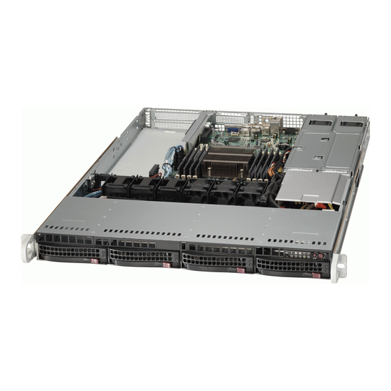
Chapter 1 Introduction Overview The SuperServer 5017R-WRF is a 1U server comprised of two main subsystems: the SC815TQ-R500WB chassis and the X9SRW-F motherboard. Please refer to our web site for information on operating systems that have been certifi ed for use with the system (www.supermicro.com). -
Page 10: Motherboard Features
ERVER 5017R-WRF User's Manual Motherboard Features At the heart of the SuperServer 5017R-WRF lies the X9SRW-F, a single processor motherboard based on the Intel® C600-A/D chipset. Below are the main features of the X9SRW-F. (See Figure 1-1 for a block diagram of the chipset). -
Page 11: Server Chassis Features
Engine (ME) fi rmware installed to use this feature. Server Chassis Features The 5017R-WRF is built upon the SC815TQ-R500WB chassis. Details on the chassis and on servicing procedures can be found in Chapter 6. The following is a general outline of the main features of the chassis. -
Page 12: System Block Diagram
UPER ERVER 5017R-WRF User's Manual Figure 1-1. Intel C600 Chipset: System Block Diagram Note: This is a general block diagram. Please see Chapter 5 for details. #0-8 #0-4 #0-7 VR12 #0-3 #0-6 #0-2 6 PHASE #0-5 #0-1 Sandybridge-EP 8 SNB CORE... -
Page 13: Contacting Supermicro
Chapter 1: Introduction Contacting Supermicro Headquarters Address: Super Micro Computer, Inc. 980 Rock Ave. San Jose, CA 95131 U.S.A. Tel: +1 (408) 503-8000 Fax: +1 (408) 503-8008 Email: marketing@supermicro.com (General Information) support@supermicro.com (Technical Support) Web Site: www.supermicro.com Europe Address: Super Micro Computer B.V. - Page 14 UPER ERVER 5017R-WRF User's Manual Notes...
-
Page 15: Chapter 2 Server Installation
If the server itself shows damage you should fi le a damage claim with the carrier who delivered it. Decide on a suitable location for the rack unit that will hold the 5017R-WRF. It should be situated in a clean, dust-free area that is well ventilated. Avoid areas where heat, electrical noise and electromagnetic fi... -
Page 16: Rack Precautions
UPER ERVER 5017R-WRF User's Manual • Leave enough clearance in front of the rack to enable you to open the front door completely (~25 inches) and approximately 30 inches of clearance in the back of the rack to allow for suffi cient airfl ow and ease in servicing.This product is for installation only in a Restricted Access Location (dedicated equipment rooms, service closets and the like). -
Page 17: Rack Mounting Considerations
Chapter 2: Server Installation • Allow the hot plug SATA drives and power supply modules to cool before touch- ing them. • Always keep the rack's front door and all panels and components on the servers closed when not servicing to maintain proper cooling. Rack Mounting Considerations Ambient Operating Temperature If installed in a closed or multi-unit rack assembly, the ambient operating tempera-... -
Page 18: Installing The System Into A Rack
ERVER 5017R-WRF User's Manual Installing the System into a Rack This section provides information on installing the 5017R-WRF into a rack unit with the rack rails provided. If the system has already been mounted into a rack, you can skip ahead to Sections 2-5 and 2-6. -
Page 19: Installing The Outer Rails
Chapter 2: Server Installation Installing the Outer Rails Begin by measuring the distance from the front rail to the rear rail of the rack. Attach a short bracket to the front side of the right outer rail and a long bracket to the rear side of the right outer rail. -
Page 20: Installing The Server Into The Rack
UPER ERVER 5017R-WRF User's Manual Installing the Server into the Rack You should now have rails attached to both the chassis and the rack unit. The next step is to install the server into the rack. Do this by lining up the rear of the chassis rails with the front of the rack rails. -
Page 21: Installing The Server Into A Telco Rack
Chapter 2: Server Installation Installing the Server into a Telco Rack To install the 5017R-WRF into a Telco type rack, use two L-shaped brackets on either side of the chassis (four total). First, determine how far follow the server will extend out the front of the rack. - Page 22 UPER ERVER 5017R-WRF User's Manual Notes...
-
Page 23: Chapter 3 System Interface
Chapter 3: System Interface Chapter 3 System Interface Overview There are several LEDs on the control panel as well as others on the SATA drive carriers to keep you constantly informed of the overall status of the system as well as the activity and health of specifi... -
Page 24: Power
UPER ERVER 5017R-WRF User's Manual Power The main power button is used to apply or remove power from the power supply to the server system. Turning off system power with this button removes the main power but keeps standby power supplied to the system. -
Page 25: Nic2
Indicates network activity on LAN2 when fl ashing. NIC1 Indicates network activity on LAN1 when fl ashing. Indicates IDE channel activity. On the SuperServer 5017R-WRF, this light indicates SATA and/or DVD-ROM drive activity when fl ashing. Power Indicates power is being supplied to the system's power supply units. This LED... -
Page 26: Hard Drive Carrier Leds
UPER ERVER 5017R-WRF User's Manual Hard Drive Carrier LEDs Each hard drive carrier has two LEDs. • Green: When illuminated, the green LED on the front of the drive carrier in- dicates drive activity. A connection to the SATA backplane enables this LED to blink on and off when that particular drive is being accessed. -
Page 27: Chapter 4 System Safety
System Safety Electrical Safety Precautions Basic electrical safety precautions should be followed to protect yourself from harm and the SuperServer 5017R-WRF from damage: • Be aware of the locations of the power on/off switch on the chassis as well as the room's emergency power-off switch, disconnection switch or electrical outlet. -
Page 28: General Safety Precautions
Keep the area around the system clean and free of clutter. • The 5017R-WRF weighs approximately 43/41 lbs (19.5/18.6 kg) when fully loaded. When lifting the system, two people at either end should lift slowly with their feet spread out to distribute the weight. Always keep your back straight and lift with your legs. -
Page 29: Esd Precautions
Chapter 4: System Safety • After accessing the inside of the system, close the system back up and secure it to the rack unit after ensuring that all connections have been made. ESD Precautions Electrostatic discharge (ESD) is generated by two objects with different electrical charges coming into contact with each other. -
Page 30: Operating Precautions
UPER ERVER 5017R-WRF User's Manual Operating Precautions Care must be taken to assure that the chassis cover is in place when the 5017R- WRF is operating to assure proper cooling. Out of warranty damage to the system can occur if this practice is not strictly followed. -
Page 31: Chapter 5 Advanced Motherboard Setup
Chapter 5: Advanced Serverboard Setup Chapter 5 Advanced Motherboard Setup This chapter covers the steps required to install processors and heatsinks to the X9SRW-F motherboard, connect the data and power cables and install add-on cards. All motherboard jumpers and connections are described and a layout and quick reference chart are included in this chapter. -
Page 32: Processor And Heatsink Installation
UPER ERVER 5017R-WRF User's Manual Processor and Heatsink Installation Notes • Always connect the power cord last and always remove it before adding, re- moving or changing any hardware components. Make sure that you install the processor into the CPU socket before you install the CPU heatsink. - Page 33 Chapter 5: Advanced Serverboard Setup 1. With the lever labeled 'Close 1st' fully retracted, gently push down on the 'Open 1st' lever to open the load plate. Lift the load plate to open it completely. Gently push 2. Using your thumb and the index down to pop the load plate fi...
- Page 34 UPER ERVER 5017R-WRF User's Manual Warning: You can only install the CPU to the socket in one direction. Make sure that the CPU is properly inserted into the socket before closing the load plate. If it doesn't close properly, do not force it as it may damage your CPU.
-
Page 35: Installing A Cpu Heatsink
Chapter 5: Advanced Serverboard Setup Installing a CPU Heatsink 1. Place the heatsink on top of the CPU so that the four mounting holes are aligned with those on the retention mechanism. 2. Screw in two diagonal screws (i.e. the #1 and the #2 screws) until just snug (do not over-tighten the screws, which may damage the CPU.) 3. -
Page 36: Connecting Cables
UPER ERVER 5017R-WRF User's Manual Connecting Cables Now that the processors are installed, the next step is to connect the cables to the motherboard. These include the data (ribbon) cables for the peripherals and control panel and the power cables. -
Page 37: I/O Ports
Chapter 5: Advanced Serverboard Setup Figure 5-1. Front Control Panel Header Pins (JF1) Ground Power LED HDD LED NIC1 LED NIC2 LED OH/Fan Fail LED UID LED PS Fail LED #3~4 Reset Button Ground Power Button Ground #1~2 I/O Ports The I/O ports are color coded in conformance with the PC 99 specifi... -
Page 38: Installing Memory
UPER ERVER 5017R-WRF User's Manual Installing Memory Note: Check the Supermicro web site for recommended memory modules. CAUTION Exercise extreme care when installing or removing DIMM modules to prevent any possible damage. Installing DIMMs 1. Insert the desired number of DIMMs into the memory slots, starting with slot DIMMA1. -
Page 39: Memory Support
Chapter 5: Advanced Serverboard Setup Memory Support The X9SRW-F supports up to 256 GB of DDR3-1600/1333/1066 ECC R/LRDIMMs (LRDIMM = Reduced Load DIMMs) or up to 64GB of ECC UDIMMs. Please refer to Chapter 5 for installing memory. Populating these DIMM modules with a pair of memory modules of the same type and same size will result in interleaved memory, which will improve memory performance. -
Page 40: Memory Population Guidelines
UPER ERVER 5017R-WRF User's Manual Memory Population Guidelines When installing memory modules, the DIMM slots should be populated in the following order: DIMM1A, DIMM2A, DIMM3A, DIMM4A then DIMM1B, DIMM2B, DIMM3B, DIMM4B. • Use DDR3 DIMM modules of the same size, type and speed. -
Page 41: Adding Pci Expansion Cards
Chapter 5: Advanced Serverboard Setup Adding PCI Expansion Cards PCI Expansion Slots Two riser cards are used to support PCI expansion cards in the system. The RSC- R1UW-E8R riser card can support a PCI-E 3.0 x8 card and the RSC-R1UW-2E16 can support two PCI-E 3.0 x16 cards. -
Page 42: Motherboard Details
UPER ERVER 5017R-WRF User's Manual Motherboard Details Figure 5-4. SUPER X9SRW-F Layout JVGA1 JLAN1 USB0/1 JCOM1 JLAN2 USB2/3 JI2C3 JUIDB1 COM1 JI2C2/JI2C3 1-2:Enable JCOM1 JVGA1 2-3:Disable JPL1:LAN1 JPG1: VGA 1-2:ENABLE JI2C2 1-2:Enable 2-3:DISABLE 2-3:Disable JPL2:LAN2 1-2:ENABLE 2-3:DISABLE LED2 IPMI JWD:... -
Page 43: X9Srw-F Quick Reference
Chapter 5: Advanced Serverboard Setup X9SRW-F Quick Reference Connector Description S-SATA1 ~ S-SATA4 SCU-based SATA 3.0 ports (6Gb/s) I-SATA0 ~ I-SATA5 Intel-based SATA ports (I-SATA0 and I-SATA1 = SATA 3.0, S-SATA1~S-SATA4 = SATA 2.0) FAN1~FAN5 Headers for system cooling fans JSD1 SATA DOM (Disk On Module) Power Connector Chassis Intrusion Header... - Page 44 UPER ERVER 5017R-WRF User's Manual Jumper Description Default JI2C2/JI2C3 SMB to PCI Slots On (Enabled) JPG1 Onboard VGA Enable/Disable Pins 1-2 (On) JPL1 LAN1/LAN2 Enable/Disable Pins 1-2 (Enabled) JPME1 Intel ME Mode Select Pins 1-2 (Normal) Unit ID Switch Off (Disabled)
-
Page 45: Connector Defi Nitions
Chapter 5: Advanced Serverboard Setup Connector Defi nitions ATX Power 24-pin Connector Pin Defi nitions (JPW1) Pin# Defi nition Pin # Defi nition ATX Power Connector +3.3V +3.3V The 24-pin main power connector -12V +3.3V (JPW1) is used to provide power to the motherboard. - Page 46 UPER ERVER 5017R-WRF User's Manual HDD LED The HDD LED connection is located HDD LED Pin Defi nitions (JF1) on pins 13 and 14 of JF1. Attach a Pin# Defi nition hard drive LED cable to display SATA/ IDE disk activity. Refer to the table on HD Active the right for pin defi...
- Page 47 Chapter 5: Advanced Serverboard Setup Reset Button Reset Button The Reset Button connection is lo- Pin Defi nitions (JF1) cated on pins 3 and 4 of JF1. Attach Pin# Defi nition it to the hardware reset switch on the Reset computer case.
- Page 48 UPER ERVER 5017R-WRF User's Manual Speaker (JD1) Speaker Connector Pin Defi nitions On the JD1 header, pins 3~4 are used Pin Setting Defi nition for the internal speaker. Close pins Pins 3~4 Internal Speaker 3~4 with a jumper or cap to use the onboard speaker.
- Page 49 Chapter 5: Advanced Serverboard Setup LAN Ports Pin Defi nition Pin# Defi nition Ethernet Ports TD0- SGND Two Ethernet ports (LAN1/LAN2) are TD0+ P3V3SB located next to the VGA port on the TD1- Act LED rear I/O.A dedicated IPMI LAN is also TD1+ Link 100 LED (Green, +3V3SB)
- Page 50 UPER ERVER 5017R-WRF User's Manual IPMB I IPMB I Pin Defi nitions (IPMB) Pin# Defi nition A System Management Bus header for the IPMI slot is located at IPMB. Data Connect the appropriate cable here Ground to use the IPMB I...
-
Page 51: Jumper Settings
Chapter 5: Advanced Serverboard Setup Jumper Settings Explanation of Jumpers To modify the operation of the mother- board, jumpers can be used to choose Connector between optional settings. Jumpers Pins create shorts between two pins to change the function of the connector. Jumper Pin 1 is identifi... - Page 52 UPER ERVER 5017R-WRF User's Manual LAN Enable/Disable LAN Enable/Disable Change the setting of jumper JPL1 to Jumper Settings enable or disable the onboard Ether- Jumper Setting Defi nition net (RJ45) ports LAN1 and LAN2. See Pins 1-2 Enabled the table on the right for jumper set-...
- Page 53 Chapter 5: Advanced Serverboard Setup BIOS Recovery BIOS Recovery Jumper Settings The BIOS Recovery jumper (JP3) is Pin# Defi nition used to enable or disable the BIOS Recover recovery feature of the motherboard. Ground Install the jumper on pins 1-2 to begin Normal (Default) the recovery process.
- Page 54 UPER ERVER 5017R-WRF User's Manual BIOS Recovery BIOS Recovery Pin Defi nitions The BIOS Recovery (JP3) is used to Pin# Defi nition enable or disable the BIOS Recovery Recover feature of the motherboard. Install Ground the jumper on pins 1-2 to begin the Normal (Default) recovery process.
-
Page 55: 5-10 Onboard Indicators
Chapter 5: Advanced Serverboard Setup 5-10 Onboard Indicators LAN Port LEDs The Ethernet ports (located beside LAN LED Connection Speed Indicator the VGA port) have two LEDs. One LED Color Defi nition LED indicates activity when blinking No connection or 10 Mb/s while the other LED may be green, Green 100 Mb/s... -
Page 56: Super Server 5017R-Wrf User's Manual
UPER ERVER 5017R-WRF User's Manual Rear Unit ID LED The rear Unit ID LED (LE2) is located Rear UID LED Indicator on the back panel. This LED is used Status Defi nition in conjunction with the rear UID switch Solid Blue UID Toggled On to provide easy identifi... -
Page 57: 5-12 Installing Software
Chapter 5: Advanced Serverboard Setup 5-12 Installing Software After the hardware has been installed, you should fi rst install the operating system and then the drivers. The necessary drivers are all included on the Supermicro CDs that came packaged with your motherboard. Driver/Tool Installation Display Screen Note: Click the icons showing a hand writing on paper to view the readme fi... -
Page 58: Superdoctor Iii
UPER ERVER 5017R-WRF User's Manual SuperDoctor III ® The SuperDoctor III program is a Web base management tool that supports remote management capability. It includes Remote and Local Management tools. The local management is called SD III Client. The SuperDoctor III program included on the CD-ROM that came with your motherboard allows you to monitor the environment and operations of your system. - Page 59 Chapter 5: Advanced Serverboard Setup SuperDoctor III Interface Display Screen (Remote Control) Note: The SuperDoctor III program and User's Manual can be downloaded from the Supermicro web site at http://www.supermicro.com/products/accessories/software/ SuperDoctorIII.cfm. For Linux, we recommend using SuperDoctor II. 5-29...
- Page 60 UPER ERVER 5017R-WRF User's Manual Notes 5-30...
-
Page 61: Chapter 6 Advanced Chassis Setup
Chapter 6: Advanced Chassis Setup Chapter 6 Advanced Chassis Setup This chapter covers the steps required to install components and perform mainte- nance on the SC815TQ-R500WB chassis. For component installation, follow the steps in the order given to eliminate the most common problems encountered. If some steps are unnecessary, skip ahead to the next step. -
Page 62: Control Panel
UPER ERVER 5017R-WRF User's Manual Figure 6-1. Chassis: Front and Rear Views Slim Floppy Drive (optional) System LEDs Control Panel Drive Bays System Reset Main Power Power Supply Module PCI Expansion Slots (w/ riser cards) I/O Backpanel Control Panel The control panel (located on the front of the chassis) must be connected to the JF1 connector on the motherboard to provide you with system status indications. -
Page 63: System Fans
System Fans Four 4-cm heavy duty counter-rotating fans provide the cooling for the SuperServer 5017R-WRF. Each fan unit is actually made up of two fans joined back-to-back, which rotate in opposite directions. This counter-rotating action generates exception- al airfl ow and works to dampen vibration levels. It is very important that the chassis top cover is properly installed and making a good seal in order for the cooling air to circulate properly through the chassis and cool the components. -
Page 64: Drive Bay Installation/Removal
UPER ERVER 5017R-WRF User's Manual Figure 6-2. System Cooling Fans Drive Bay Installation/Removal Removing the Front Bezel If your system has a front bezel (optional) attached to the chassis, you must fi rst remove it to gain access to the drive bays. To remove the bezel, fi rst unlock the front of the chassis then press the release knob (see Figure 6-3). -
Page 65: Accessing The Drive Bays
DVD-ROM/Floppy Disk Drives: For installing/removing a DVD-ROM or fl oppy disk drive, you will need to gain access to the inside of the 5017R-WRF by removing the top cover of the chassis. Proceed to the "DVD-ROM and Floppy Drive Installation"... -
Page 66: Hard Drive Installation
UPER ERVER 5017R-WRF User's Manual Hard Drive Installation The hard drives are mounted in drive carriers to simplify their installation and removal from the chassis. These carriers also help promote proper airfl ow for the drive bays. For this reason, even empty carriers without drives installed must remain in the chassis. - Page 67 Chapter 6: Advanced Chassis Setup Installing/Removing a Hard Drive 1. To remove a carrier, push the release button located beside the drive LEDs. 2. Swing the colored handle fully out and use it to pull the unit straight out (see Figure 6-5).
-
Page 68: Dvd-Rom And Floppy Drive Installation
fl oppy drive bays. The 5017R-WRF accomodates only slim-line DVD-ROM drives. Side mounting brackets are needed to mount a slim-line DVD-ROM drive in the 5017R-WRF server. You must power down the system before installing or removing a fl oppy or DVD-ROM drive. -
Page 69: Power Supply
B. Power Supply The SuperServer 5017R-WRF has a 500 watt redundant power supply confi guration consisting of two hot-swap power modules. The power supply modules have an auto-switching capability, which enables them to automatically sense and operate with a 100V - 240V input voltage. - Page 70 UPER ERVER 5017R-WRF User's Manual Figure 6-6. Removing/Replacing the Power Supply 6-10...
-
Page 71: Chapter 7 Bios
Chapter 7: BIOS Chapter 7 BIOS Introduction This chapter describes the AMI BIOS Setup Utility for the X9SRW motherboard. The AMI ROM BIOS is stored in a Flash EEPROM and can be easily updated. This chapter describes the basic navigation of the AMI BIOS Setup Utility setup screens. SAS features are not included on the X9SRW. -
Page 72: How To Start The Setup Utility
UPER ERVER 5017R-WRF User's Manual How to Start the Setup Utility Normally, the only visible Power-On Self-Test (POST) routine is the memory test. As the memory is being tested, press the <Delete> key to enter the main menu of the AMI BIOS Setup Utility. From the main menu, you can access the other setup screens. - Page 73 Chapter 7: BIOS The AMI BIOS main menu displays the following information: BIOS Information BIOS Vendor This item displays the name of the BIOS vendor. Core Version This item displays the core version of the BIOS. Compliancy This item displays the compliance information of the BIOS. Project Version This item displays the version number of the project.
-
Page 74: Advanced Setup Confi Gurations
UPER ERVER 5017R-WRF User's Manual Advanced Setup Confi gurations Use the arrow keys to select Boot Setup and hit <Enter> to access the submenu items: Legacy OpROM Support Launch PXE OpROM The options are Enabled and Disabled. Launch Storage OpROM The options are Enabled and Disabled. -
Page 75: Pci Express Settings
Chapter 7: BIOS PCI bit Resource Handling Above 4G Decoding Set this item to Enabled to activate 64-bit capable devices to be decoded above the 4G address space. This works only if the system supports 64-bit PCI decod- ing. The options are Enabled and Disabled. PCI Common Settings PCI Latency Timer This feature sets the latency Timer of each PCI device installed on a PCI bus. - Page 76 UPER ERVER 5017R-WRF User's Manual Maximum Payload This feature selects the setting for the PCIE maximum payload size. The op- tions are Auto, 128 Bytes, 256 Bytes, 512 Bytes, 1024 Bytes, 2048 Bytes, and 4096 Bytes. Maximum Read Request This feature selects the setting for the PCIE maximum Read Request size. The options are Auto, 128 Bytes, 256 Bytes, 512 Bytes, 1024 Bytes, 2048 Bytes, and 4096 Bytes.
- Page 77 Chapter 7: BIOS longer timeout range supported by the device. The options are Default, Shorter, Longer, and Disabled. ARI (Alternative Routing-ID Interpretation) Forwarding (Available if supported by a device) If this feature is set to Enabled, Downstream PCI-E ports do not force the Device Number=0 restriction.
-
Page 78: Acpi Settings
UPER ERVER 5017R-WRF User's Manual End-End TLP Prefi x Blocking (Available if supported by a device) If this feature is set to Enabled and is supported by the device, TLP forwarding that contains End-End TLP prefi xes will be blocked. The options are Disabled and Enabled. -
Page 79: Trusted Computing
Chapter 7: BIOS ACPI Sleep State Use this feature to select the ACPI State when the system is in sleep mode. Select S1 (CPU Stop Clock) to erase all CPU caches and stop executing instructions. Power to the CPU(s) and RAM is maintained, but RAM is refreshed. Select Suspend to use power-reduced mode. - Page 80 UPER ERVER 5017R-WRF User's Manual WHEA Confi guration WHEA Support Select Enabled to enable Windows Hardware Error Architecture (WHEA) support which will provide a common infrastructure for the system to handle hardware errors on the Windows OS platforms in order to reduce system crashes due to hardware errors and to enhance system recovery and health monitoring.
- Page 81 Chapter 7: BIOS 64-bit This item indicates if the CPU installed supports 64-bit technology. Hyper-threading Select Enabled to support Intel Hyper-threading Technology to enhance CPU per- formance. The options are Enabled and Disabled. Active Processor Cores Set to Enabled to use a processor's Second Core and beyond. (Please refer to Intel's web site for more information.) The options are All, 1, 2, 3, 4, 5, 6 and 7.
- Page 82 UPER ERVER 5017R-WRF User's Manual Intel® Virtualization Technology Select Enabled to support Intel Virtualization Technology, whch will allow one platform to run multiple operating systems and applications in independent parti- tions, creating multiple "virtual" systems in one physical computer. The options are Enabled and Disabled.
-
Page 83: Runtime Error Logging
Chapter 7: BIOS Package C State Limit If set to Auto, the AMI BIOS will automatically set the limit on the C-State package register. The options are C0, C1, C6, C7, and No Limit. Energy Performance The options are Performance, Balanced Performance, Balanced Energy, and Energy Effi... - Page 84 UPER ERVER 5017R-WRF User's Manual PCI Error Logging Support Select Enabled to support error event logging for PCI Slots. The options are En- abled and Disabled. Poison Support Select Enabled for Poison support. The options are Enabled and Disabled. ...
- Page 85 Chapter 7: BIOS External SATA Port 0~5 Select Enabled to enable Extended SATA Port 0 ~ Port 5 support. The op- tions are Enabled and Disabled. Staggered Spin-up Select Enabled to enable Staggered Spin-up support to prevent excessive power consumption caused by multiple HDDs spinning-up simultaneously. The options are Enabled and Disabled.
- Page 86 UPER ERVER 5017R-WRF User's Manual USB Confi guration Legacy USB Support Select Enabled to support legacy USB debvices. Select Auto to disable legacy sup- port if USB devices are not present. Select Disable to have USB devices available for EFI (Extensive Firmware Interface) applicatioins only. The options are Enabled, Disabled and Auto.
-
Page 87: Serial Port Console Redirection
Chapter 7: BIOS Serial Port Select Enabled to enable a serial port specifi ed by the user. The options are Enabled and Disabled. Serial Port Mode The options are SOL and COM. Device Settings This feature indicates whether or not a reset is required for a serial port specifi ed. Change Settings Use this feature to set the optimal Platform Environment Control Interface (PECI) setting for a serial port specifi... - Page 88 UPER ERVER 5017R-WRF User's Manual Terminal Type This feature allows the user to select the target terminal emulation type for Con- sole Redirection. Selet VT100 to use the ASCII character set. Select VT100+ to add color and function key support. Select ANSI to use the extended ASCII character set.
-
Page 89: Network Stack
Chapter 7: BIOS Recorder Mode Select Enabled to capture the data displayed on a terminal and send it as text messages to a remote server. The options are Disabled and Enabled. Resolution 100x31 Select Enabled for extended-terminal resolution support. The options are Dis- abled and Enabled. - Page 90 UPER ERVER 5017R-WRF User's Manual Enable iSCSI Select Enabled to enable iSCSI support. The options are Disabled and Enabled. Enable DHCP Select Enabled to enable Dynamic Host Confi guration Protocol (DHCP) support, which will allow the BIOS to search for a DHCP server in the network to fi nd the available IP address for this computer.
-
Page 91: Chipset Confi Guration Settings
Chapter 7: BIOS Chipset Confi guration Settings Use the arrow keys to select Chipset and display the following submenu items. North Bridge This feature allows the user to confi gure the settings for the Intel North Bridge. IOH (IO Hub) Confi guration ... - Page 92 UPER ERVER 5017R-WRF User's Manual If Enabled is selected, the following items appear: Interrupt Remapping The options are Disabled and Enabled. Coherency Support The options are Disabled and Enabled. ATS Support The options are Disabled and Enabled. Pass-through DMA The options are Disabled and Enabled.
- Page 93 Chapter 7: BIOS Mmio Ratio Skt0 (Available when IOH Resource Selection Type is set to Manual) The default setting is 6. IOH PCIe Port Bifuracation Control This submenu allows the user to confi gure the following 10 PCIe Port Bifurcation Control settings for the IOH 0/IOH 1 PCI-Exp ports.
- Page 94 UPER ERVER 5017R-WRF User's Manual Memory Mode When Independent is selected, all DIMMs are available to the operating system. When Mirroring is selected, the motherboard maintains two identical copies of all data in memory for data backup. When Lockstep is selected, the motherboard uses two areas of memory to run the same set of operations in parallel.
-
Page 95: South Bridge
Chapter 7: BIOS Rank Margin Select Enabled to set the memory rank margin setting. The options are Disabled and Enabled. Thermal Throttling Throttling improves reliability and reduces power consumption in the processor via automatic voltage control during processor idle states. The options are Disabled CLTT (Closed Loop Thermal Throttling), and OLTT (Open Loop Thermal Throttling). - Page 96 UPER ERVER 5017R-WRF User's Manual SB (South Bridge) Chipset Confi guration PCH Compatibility RID Select Enabled to enable Compatibly Revision ID (CRID) support which will modify the chipset's PCI identifi ers for compatibility reasons. The options are Disabled and Enabled.
- Page 97 Chapter 7: BIOS High Precision Event Timer Confi guration High Precision Timer Select Enabled to activate the High Precision Event Timer (HPET) that produces periodic interrupts at a much higher frequency than a Real-time Clock (RTC) does in synchronizing multimedia streams, providing smooth playback, reducing the de- pendency on other timestamp calculation devices, such as an x86 RDTSC Instruc- tion embedded in the CPU.
- Page 98 UPER ERVER 5017R-WRF User's Manual ME Subsystem Select Enabled to support Intel Management Engine (ME) Subsystem, a small power computer subsystem that performs various tasks in the background. The options are Enabled and Disabled. When ME Subsystem is enabled, the following items will display.
-
Page 99: Server Management
Chapter 7: BIOS Server Management Use this feature to confi gure Server Management settings. BMC Support Select Enabled to enable the BMC (Baseboard Management Controller). The op- tions are Enabled and Disabled. Wait for BMC Select Enabled for the system to wait for the host controller to initiate and to interface with the BMC at bootup. - Page 100 UPER ERVER 5017R-WRF User's Manual Erasing Settings Erase SEL Select 'Yes, On next reset' to erase all system event logs upon next system reboot. Select 'Yes, On every reset' to erase all system event logs upon each system reboot. Select No to keep all system event logs after each system reboot.
-
Page 101: Boot
Chapter 7: BIOS Station IP Address This item displays the Station IP address for this computer. This should be in decimal and in dotted quad form (i.e., 192.168.10.253). Subnet Mask This item displays the sub-network that this computer belongs to. The value of each three-digit number separated by dots should not exceed 255. - Page 102 UPER ERVER 5017R-WRF User's Manual Boot Confi guration Setup Prompt Timeout This item allows the user to specify the number of seconds the system should wait before the setup is initiated. The default setting is 1. Boot NumLock State Use this feature to set the Power-on state for the Numlock key. The options are Off and On.
-
Page 103: Security
Chapter 7: BIOS Boot Option Priorities Boot Option #1/ Boot Option #2/ Boot Option #3 This item allows the user to select the fi rst boot device. Select a LAN device to boot the system from the network connection. Select UEFI to boot the system from the UEFI: Built-in EFI Shell. -
Page 104: Save & Exit
UPER ERVER 5017R-WRF User's Manual Administrator Password Use this feature to set the Administrator Password which is required to enter the BIOS setup utility. The length of the password should be from 3-characters to 8-characters long. User Password Use this feature to set a User Password which is required to log into the system and to enter the BIOS setup utility. - Page 105 Chapter 7: BIOS Discard Changes and Exit Select this option to quit the BIOS Setup without making any permanent changes to the system confi guration, and reboot the computer. Select Discard Changes and Exit from the Exit menu and press <Enter>. When the dialog box appears, asking you if you want to exit the BIOS setup without saving, click Yes to quit BIOS without saving the changes, or click No to quit the BIOS and save changes.
- Page 106 UPER ERVER 5017R-WRF User's Manual user's defaults, click Yes to save the current values as user's default settings, or click No to keep the defaults previously saved as the user's defaults. Restore User Defaults Select this feature and press <Enter> to load the user's defaults previously saved in the system.
-
Page 107: Appendix A Bios Error Beep Codes
Appendix A: BIOS Error Beep Codes Appendix A BIOS Error Beep Codes During the POST (Power-On Self-Test) routines, which are performed each time the system is powered on, errors may occur. Non-fatal errors are those which, in most cases, allow the system to continue with bootup. - Page 108 UPER ERVER 5017R-WRF User's Manual Notes...
-
Page 109: Appendix B System Specifi Cations
Appendix B: System Specifi cations Appendix B System Specifi cations Processors Single Intel Xeon E5-2600/E5-1600 series processor in an LGA2011 socket Note: Please refer to our web site for a complete listing of supported processors. Chipset Intel C600-A/D chipset BIOS 8 Mb Award®... - Page 110 UPER ERVER 5017R-WRF User's Manual Weight Gross (Bare Bone): 43 lbs. (19.5 kg.) System Cooling Four 4-cm heavy-duty counter-rotating fans System Input Requirements AC Input Voltage: 100-240V AC auto-range Rated Input Current: 6.1A - 2.6A Rated Input Frequency: 50 to 60 Hz...
- Page 111 Appendix B: System Specifi cations Notes...
- Page 112 UPER ERVER 5017R-WRF User's Manual (continued from front) The products sold by Supermicro are not intended for and will not be used in life support systems, medical equipment, nuclear facilities or systems, aircraft, aircraft devices, aircraft/emergency com- munication devices or other critical systems whose failure to perform be reasonably expected to result in signifi...
Need help?
Do you have a question about the SUPERSERVER 5017R-WRF and is the answer not in the manual?
Questions and answers