Table of Contents
Advertisement
Quick Links
Advertisement
Table of Contents

Related Manuals for Supero SUPERSERVER 5017A-EF


Summary of Contents for Supero SUPERSERVER 5017A-EF
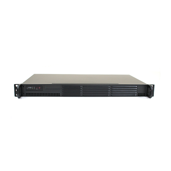
- Page 1 ® UPER UPER ERVER 5017A-EF USER’S MANUAL...
- Page 2 This product, including software and docu- mentation, is the property of Supermicro and/or its licensors, and is supplied only under a license. Any use or reproduction of this product is not allowed, except as expressly permitted by the terms of said license.
-
Page 3: About This Manual
SuperServer 5017A-EF. Installation and maintainance should be performed by experienced technicians only. The SuperServer 5017A-EF is a high-end server based on the SC504-203B rack- mountable chassis and the X9SBAA-F single processor serverboard. - Page 4 UPER ERVER 5017A-EF User's Manual Chapter 5: Advanced Serverboard Setup Chapter 5 provides detailed information on the X9SBAA-F serverboard, including the locations and functions of connections, headers and jumpers. Refer to this chapter when adding or removing processors or main memory and when reconfi guring the serverboard.
- Page 5 Preface Notes...
-
Page 6: Table Of Contents
UPER ERVER 5017A-EF User's Manual Table of Contents Chapter 1 Introduction Overview ......................1-1 Motherboard Features ..................1-2 Processors ...................... 1-2 Memory ......................1-2 Serial ATA ......................1-2 PCI Expansion Slots ..................1-2 Rear I/O Ports ....................1-2 Server Chassis Features ................1-3 System Power .................... - Page 7 Table of Contents Control Panel LEDs ..................3-2 Power Fail ....................... 3-2 NIC1 ........................ 3-2 NIC2 ........................ 3-2 HDD ......................... 3-3 Power ......................3-3 Chapter 4 Standardized Warning Statements for AC Systems About Standardized Warning Statements ............4-1 Warning Defi nition ................... 4-1 Installation Instructions ..................
- Page 8 UPER ERVER 5017A-EF User's Manual Jumper Settings .................... 5-13 5-10 Onboard Indicators ..................5-15 5-11 SATA Ports ....................5-16 5-12 Installing Software ..................5-17 SuperDoctor III ....................5-18 5-13 Operating Precautions .................. 5-20 Chapter 6 Advanced Chassis Setup Static-Sensitive Devices .................. 6-1 Precautions .....................
-
Page 9: Chapter 1 Introduction
In addition to the motherboard and chassis, various hardware components have been included with the 5017A-EF, as listed below: • One riser card bracket (MCP-120-00063-0N) • One riser card (RSC-R1U-33) Note: a complete list of safety warnings is provided on the Supermicro web site at http://www.supermicro.com/about/policies/safety_information.cfm... -
Page 10: Motherboard Features
UPER ERVER 5017A-EF User's Manual Motherboard Features The SuperServer 5017A-EF is built around the X9SBAA-F, a single processor moth- erboard designed to provide maximum performance. Below are the main features of the X9SBAA-F. Processors The X9SBAA-F supports a single Intel® Atom SoC S1260 embedded processor. -
Page 11: Server Chassis Features
Chapter 1: Introduction Server Chassis Features The SC504-203B is a mini-ITX form factor chassis designed to be used in a 1U rackmount confi guration. The following is a general outline of the main features of the SC504-203B server chassis. System Power The SC504-203B features a single 200W power supply. -
Page 12: Contacting Supermicro
UPER ERVER 5017A-EF User's Manual Contacting Supermicro Headquarters Address: Super Micro Computer, Inc. 980 Rock Ave. San Jose, CA 95131 U.S.A. Tel: +1 (408) 503-8000 Fax: +1 (408) 503-8008 Email: marketing@supermicro.com (General Information) support@supermicro.com (Technical Support) Web Site: www.supermicro.com Europe Address: Super Micro Computer B.V. -
Page 13: Chapter 2 Server Installation
Precautions in the next section. Preparing for Setup The box the SuperServer 5017A-EF was shipped in should include two sets of rail assemblies, two rail mounting brackets and the mounting screws you will need to install the system into the rack. Follow the steps in the order given to complete the installation process in a minimum amount of time. -
Page 14: Warnings And Precautions
UPER ERVER 5017A-EF User's Manual • This product is for installation only in a Restricted Access Location (dedicated equipment rooms, service closets and the like). • This product is not suitable for use with visual display work place devices acccording to §2 of the the German Ordinance for Work with Visual Display Units. -
Page 15: Rack Mounting Considerations
Chapter 2: Server Installation Rack Mounting Considerations Ambient Operating Temperature If installed in a closed or multi-unit rack assembly, the ambient operating tempera- ture of the rack environment may be greater than the ambient temperature of the room. Therefore, consideration should be given to installing the equipment in an environment compatible with the manufacturer’s maximum rated ambient tempera- ture (Tmra). -
Page 16: Installing The System Into A Rack
UPER ERVER 5017A-EF User's Manual Installing the System into a Rack This section provides information on installing the SC504 chassis into a rack unit. There are a variety of rack units on the market, which may mean the assembly procedure will differ slightly. You should also refer to the installation instructions that came with the rack unit you are using. -
Page 17: Telco Rack
Chapter 2: Server Installation Stability hazard. The rack stabilizing mechanism must be in place, or the rack must be bolted to the fl oor before you slide the unit out for servicing. Failure to stabilize the rack can cause the rack to tip over. Telco Rack The SC504 supports Telco Rack installation. -
Page 18: Installing The Chassis Into A Telco Rack
UPER ERVER 5017A-EF User's Manual Installing the Chassis into a Telco Rack 1. To install the chassis into a Telco style two-post rack, use two L-shaped brackets on either side of the chassis (four total). 2. First, determine how far follow the server will extend out the front of the rack. -
Page 19: Chapter 3 System Interface
Chapter 3: System Interface Chapter 3 System Interface Overview There are several LEDs on the control panel as well as others on the drive carriers to keep you constantly informed of the overall status of the system and the activ- ity and health of specifi... -
Page 20: Control Panel Leds
SUPERSERVER 5017A-EF User's Manual Control Panel LEDs The control panel located on the front of the chassis has fi ve LEDs. These LEDs provide you with critical information related to different parts of the system. This section explains what each LED indicates when illuminated and any corrective ac- tion you may need to take. -
Page 21: Hdd
Chapter 3: System Interface On the SuperServer 5017A-EF, this LED indicates SATA drive activity when fl ashing. Power Indicates power is being supplied to the system's power supply units. This LED should normally be illuminated when the system is operating. - Page 22 SUPERSERVER 5017A-EF User's Manual Notes...
-
Page 23: Chapter 4 Standardized Warning Statements For Ac Systems
The following statements are industry standard warnings, provided to warn the user of situations which have the potential for bodily injury. Should you have questions or experience difficulty, contact Supermicro's Technical Support department for assistance. Only certifi ed technicians should attempt to install or confi gure components. - Page 24 UPER ERVER 5017A-EF User's Manual Warnung WICHTIGE SICHERHEITSHINWEISE Dieses Warnsymbol bedeutet Gefahr. Sie befi nden sich in einer Situation, die zu Verletzungen führen kann. Machen Sie sich vor der Arbeit mit Geräten mit den Gefahren elektrischer Schaltungen und den üblichen Verfahren zur Vorbeugung vor Unfällen vertraut.
- Page 25 Warning Statements for AC Systems BELANGRIJKE VEILIGHEIDSINSTRUCTIES Dit waarschuwings symbool betekent gevaar. U verkeert in een situatie die lichamelijk letsel kan veroorzaken. Voordat u aan enige apparatuur gaat werken, dient u zich bewust te zijn van de bij een elektrische installatie betrokken risico's en dient u op de hoogte te zijn van de standaard procedures om ongelukken te voorkomen.
-
Page 26: Installation Instructions
UPER ERVER 5017A-EF User's Manual Installation Instructions Warning! Read the installation instructions before connecting the system to the power source. 警告 将此系统连接电源前,请先阅读安装说明。 警告 將系統與電源連接前,請先閱讀安裝說明。 Warnung Vor dem Anschließen des Systems an die Stromquelle die Installationsanweisungen lesen. ¡Advertencia! Lea las instrucciones de instalación antes de conectar el sistema a la red de alimentación. -
Page 27: Circuit Breaker
Chapter 4: Warning Statements for AC Systems Circuit Breaker Warning! This product relies on the building's installation for short-circuit (overcurrent) protection. Ensure that the protective device is rated not greater than: 250 V, 20 A. 警告 此产品的短路(过载电流)保护由建筑物的供电系统提供,确保短路保护设备的额定电 流不大于250V,20A。 警告 此產品的短路(過載電流)保護由建築物的供電系統提供,確保短路保護設備的額定電 流不大於250V,20A。... -
Page 28: Power Disconnection Warning
UPER ERVER 5017A-EF User's Manual Waarschuwing Dit product is afhankelijk van de kortsluitbeveiliging (overspanning) van uw electrische installatie. Controleer of het beveiligde aparaat niet groter gedimensioneerd is dan 220V, 20A. Power Disconnection Warning Warning! The system must be disconnected from all sources of power and the power cord removed from the power supply module(s) before accessing the chassis interior to install or remove system components. - Page 29 Chapter 4: Warning Statements for AC Systems ¡Advertencia! El sistema debe ser disconnected de todas las fuentes de energía y del cable eléctrico quitado de los módulos de fuente de alimentación antes de tener acceso el interior del chasis para instalar o para quitar componentes de sistema. Attention Le système doit être débranché...
-
Page 30: Equipment Installation
UPER ERVER 5017A-EF User's Manual Equipment Installation Warning! Only trained and qualifi ed personnel should be allowed to install, replace, or service this equipment. 警告 只有经过培训且具有资格的人员才能进行此设备的安装、更换和维修。 警告 只有經過受訓且具資格人員才可安裝、更換與維修此設備。 Warnung Das Installieren, Ersetzen oder Bedienen dieser Ausrüstung sollte nur geschultem, qualifi ziertem Personal gestattet werden. -
Page 31: Restricted Area
Chapter 4: Warning Statements for AC Systems Waarschuwing Deze apparatuur mag alleen worden geïnstalleerd, vervangen of hersteld door geschoold en gekwalifi ceerd personeel. Restricted Area Warning! This unit is intended for installation in restricted access areas. A restricted access area can be accessed only through the use of a special tool, lock and key, or other means of security. -
Page 32: Battery Handling
UPER ERVER 5017A-EF User's Manual Waarschuwing Dit apparaat is bedoeld voor installatie in gebieden met een beperkte toegang. Toegang tot dergelijke gebieden kunnen alleen verkregen worden door gebruik te maken van speciaal gereedschap, slot en sleutel of andere veiligheidsmaatregelen. Battery Handling Warning! There is the danger of explosion if the battery is replaced incorrectly. - Page 33 Chapter 4: Warning Statements for AC Systems Warnung Bei Einsetzen einer falschen Batterie besteht Explosionsgefahr. Ersetzen Sie die Batterie nur durch den gleichen oder vom Hersteller empfohlenen Batterietyp. Entsorgen Sie die benutzten Batterien nach den Anweisungen des Herstellers. Attention Danger d'explosion si la pile n'est pas remplacée correctement. Ne la remplacer que par une pile de type semblable ou équivalent, recommandée par le fabricant.
-
Page 34: Redundant Power Supplies
UPER ERVER 5017A-EF User's Manual Redundant Power Supplies Warning! This unit might have more than one power supply connection. All connections must be removed to de-energize the unit. 警告 此部件连接的电源可能不止一个,必须将所有电源断开才能停止给该部件供电。 警告 此裝置連接的電源可能不只一個,必須切斷所有電源才能停止對該裝置的供電。 Warnung Dieses Gerät kann mehr als eine Stromzufuhr haben. Um sicherzustellen, dass der Einheit kein trom zugeführt wird, müssen alle Verbindungen entfernt werden. -
Page 35: Backplane Voltage
Chapter 4: Warning Statements for AC Systems Waarschuwing Deze eenheid kan meer dan één stroomtoevoeraansluiting bevatten. Alle aansluitingen dienen verwijderd te worden om het apparaat stroomloos te maken. Backplane Voltage Warning! Hazardous voltage or energy is present on the backplane when the system is operating. -
Page 36: Comply With Local And National Electrical Codes
UPER ERVER 5017A-EF User's Manual Waarschuwing Een gevaarlijke spanning of energie is aanwezig op de backplane wanneer het systeem in gebruik is. Voorzichtigheid is geboden tijdens het onderhoud. Comply with Local and National Electrical Codes Warning! Installation of the equipment must comply with local and national electrical codes. -
Page 37: Product Disposal
Chapter 4: Warning Statements for AC Systems Attention L'équipement doit être installé conformément aux normes électriques nationales et locales. Waarschuwing Bij installatie van de apparatuur moet worden voldaan aan de lokale en nationale elektriciteitsvoorschriften. Product Disposal Warning! Ultimate disposal of this product should be handled according to all national laws and regulations. -
Page 38: Hot Swap Fan Warning
UPER ERVER 5017A-EF User's Manual ¡Advertencia! Al deshacerse por completo de este producto debe seguir todas las leyes y reglamentos nacionales. Attention La mise au rebut ou le recyclage de ce produit sont généralement soumis à des lois et/ou directives de respect de l'environnement. Renseignez-vous auprès de l'organisme compétent. - Page 39 Chapter 4: Warning Statements for AC Systems 警告 當您從機架移除風扇裝置,風扇可能仍在轉動。小心不要將手指、螺絲起子和其他 物品太靠近風扇。 Warnung Die Lüfter drehen sich u. U. noch, wenn die Lüfterbaugruppe aus dem Chassis genommen wird. Halten Sie Finger, Schraubendreher und andere Gegenstände von den Öffnungen des Lüftergehäuses entfernt. ¡Advertencia! Los ventiladores podran dar vuelta cuando usted quite ell montaje del ventilador del chasis.
-
Page 40: Power Cable And Ac Adapter
fi re. Electrical Appliance and Material Safety Law prohibits the use of UL or CSA -certifi ed cables (that have UL/CSA shown on the code) for any other electrical devices than products designated by Supermicro only. 警告... - Page 41 Appareils électroménagers et de loi sur la sécurité Matériel interdit l'utilisation de UL ou CSA câbles certifi és qui ont UL ou CSA indiqué sur le code pour tous les autres appareils électriques que les produits désignés par Supermicro seulement.
- Page 42 UPER ERVER 5017A-EF User's Manual Notes 4-20...
-
Page 43: Chapter 5 Advanced Motherboard Setup
Chapter 5: Advanced Motherboard Setup Chapter 5 Advanced Motherboard Setup This chapter covers the steps required to connect the data and power cables and install add-on cards. All motherboard jumpers and connections are also described. A layout and quick reference chart are included in this chapter for your reference. Remember to completely close the chassis when you have fi... -
Page 44: Connecting Cables
UPER ERVER 5017A-EF User's Manual Connecting Cables Now that the motherboard is installed, the next step is to connect the cables to the board. These include the data cables for the peripherals and control panel and the power cables. Connecting Data Cables The cables used to transfer data from the peripheral devices have been carefully routed to prevent them from blocking the fl... -
Page 45: Rear I/O Ports
Chapter 5: Advanced Motherboard Setup Figure 5-1. Control Panel Header Pins Rear I/O Ports The I/O ports are color coded in conformance with the PC 99 specifi cation. See Figure 5-2 below for the colors and locations of the various I/O ports. Figure 5-2. -
Page 46: Onboard Processor And Heatsink
The X9SBAA-F motherboard supports up to 8GB of unbuffered ECC DDR3-1333 memory. Adding PCI Add-On Cards The 5017A-EF can accommodate a single riser card to support a 32-bit 5V PCI add-on card Installing an Add-on Card 1. Begin by removing the shield for the PCI slot where the riser card is located. - Page 47 Chapter 5: Advanced Motherboard Setup 1. Position the SO-DIMM mod- Align ule's bottom key so that it aligns with the receptive point on the slot. 2. Insert the SO-DIMM module vertically at about a 45 degree angle. 3. Press down until the module locks into place.
-
Page 48: Motherboard Details
UPER ERVER 5017A-EF User's Manual Motherboard Details Figure 5-4. X9SBAA-F Layout Notes • " " indicates the location of "Pin 1". • Jumpers not indicated are for test purposes only. -
Page 49: X9Sbaa-F Quick Reference
Chapter 5: Advanced Motherboard Setup X9SBAA-F Quick Reference Item # Jumper Description Default JPB1 BMC Enable/Disable Pins 1-2 (Enabled) On-board VGA Enable/ JPG1 Pins 1-2 (Enabled) Disable JWD1 Watch Dog Timer Reset Pins 1-2 (Enabled) JBT1 CMOS Reset See Section 5-9 JPL1 LAN Enable/Disable Pins 1-2 (Enabled) -
Page 50: Connector Defi Nitions
UPER ERVER 5017A-EF User's Manual Connector Defi nitions ATX Power 24-pin Connector ATX Power Connectors (JPW1) Pin Defi nitions (JPW1) Pin# Defi nition Pin # Defi nition The 24-pin (JPW1) power connector +3.3V +3.3V is used to provide power to the moth- -12V +3.3V... - Page 51 Chapter 5: Advanced Motherboard Setup NMI Button NMI Button Pin Defi nitions (JF1) The non-maskable interrupt button Pin# Defi nition header is located on pins 19 and 20 of Signal JF1. Refer to the table on the right for Ground pin defi...
- Page 52 UPER ERVER 5017A-EF User's Manual System Management System Management Bus (JIPMB1 Pin# Defi nition A System Management Bus header for Clock the IPMI slot is located at IPMB. Connect Ground the appropriate cable here to use the Data IPMB I2C connection on your system.
- Page 53 Chapter 5: Advanced Motherboard Setup Power LED/Speaker (JD1) On the JD1 header, pins 1~3 are used for Speaker Connector Pin Defi nitions a power LED and pins 4~7 are used for Pin Setting Defi nition an external speaker. If you wish to use Pins 6-7 Internal Speaker the onboard speaker, you should close...
- Page 54 UPER ERVER 5017A-EF User's Manual Serial Ports Serial Port (COM3/COM1) Pin Defi nitions There is one COM port on the I/O back Pin # Defi nition Pin # Defi nition panel (COM3) and one COM header on the motherboard (COM1). These COM ports provide high-speed 16550-compat- ible serial communication support.
-
Page 55: Jumper Settings
Chapter 5: Advanced Motherboard Setup Jumper Settings Explanation of Jumpers To modify the operation of the mother- board, jumpers can be used to choose Connector between optional settings. Jumpers Pins create shorts between two pins to change the function of the connector. Pin 1 is identifi... - Page 56 UPER ERVER 5017A-EF User's Manual BMC Enable/Disable (JPB1) JPB1 is used to enable or disable the BMC IPMI Enable/Disable Jumper Settings BMC (Baseboard Management Control) Settings Defi nition chip and the onboard IPMI connection. Pins 1-2 Enabled (Default) This jumper is used together with the IPMI...
-
Page 57: 5-10 Onboard Indicators
Chapter 5: Advanced Motherboard Setup 5-10 Onboard Indicators LAN Port LEDs GLAN Link/Speed LED Indicator LED Color Defi nition Two LAN ports are located on the I/O back- No Connection or 10 panel. Each Ethernet LAN port has two Mbps LEDs. -
Page 58: 5-11 Sata Ports
UPER ERVER 5017A-EF User's Manual System Power LED (LE1) Onboard PWR LED (LE1) LED Status An System Power LED is located at LE1 Status Defi nition on the motherboard. When LE1 is on, System Off (Soft Switch) the AC power cable is connected and the System is Running system is running. -
Page 59: 5-12 Installing Software
Chapter 5: Advanced Motherboard Setup 5-12 Installing Software The Supermicro ftp site contains drivers and utilities for your system at ftp://ftp. supermicro.com. Some of these must be installed, such as the chipset driver. After accessing the ftp site, go into the CDR_Images directory and locate the ISO fi... -
Page 60: Superdoctor Iii
UPER ERVER 5017A-EF User's Manual SuperDoctor III The SuperDoctor® III program is a web-based management tool that supports remote management capability. It includes Remote and Local Management tools. The local management is called SD III Client. The SuperDoctor III program allows you to monitor the environment and operations of your system. - Page 61 Chapter 5: Advanced Motherboard Setup Figure 5-8. SuperDoctor III Interface Display Screen (Remote Control) Note: The SuperDoctor III program and User’s Manual can be downloaded from the Supermicro web site at http://www.supermicro.com/products/accessories/soft- ware/SuperDoctorIII.cfm. For Linux, we recommend that you use the SuperDoctor II application instead.
-
Page 62: 5-13 Operating Precautions
ERVER 5017A-EF User's Manual 5-13 Operating Precautions Care must be taken to assure that the chassis cover is in place when the 5017A-EF is operating to assure proper cooling. Out of warranty damage to the system can occur if this practice is not strictly followed. -
Page 63: Chapter 6 Advanced Chassis Setup
Chapter 6: Advanced Chassis Setup Chapter 6 Advanced Chassis Setup This chapter covers the steps required to install components and perform mainte- nance on the SC504-203B chassis. For component installation, follow the steps in the order given to eliminate the most common problems encountered. If some steps are unnecessary, skip ahead to the step that follows. -
Page 64: Control Panel
UPER ERVER 5017A-EF User's Manual Figure 6-1. Front and Rear Chassis Views Control Panel Power Supply Low-profi le PCI Slot Rear I/O Ports (see Figure 5-2) Control Panel The control panel (located on the front of the chassis) must be connected to the JF1 connector on the serverboard to provide you with system status indications. -
Page 65: Removing The Chassis Cover
Chapter 6: Advanced Chassis Setup Removing the Chassis Cover Figure 6-2. Removing the Chassis Cover Removing the Chassis Cover 1. Power down the system and disconnect the power cord from the back of the power supply. 2. Remove the fi ve screws that hold the chassis cover in place. There are two screws on each side of the chassis, and one screw on the back. -
Page 66: System Fans (Optional)
UPER ERVER 5017A-EF User's Manual System Fans (Optional) Up to three optional system fans may be installed in the SC504 chassis. Installing Optional System Fans 1. Position the dual system fan housing in the front of the chassis, facing for- ward as illustrated above, in front of the motherboard. - Page 67 Chapter 6: Advanced Chassis Setup Installing 2.5" Hard Drives 2.5" hard drives may be installed in several different confi gurations. Review the supported confi guration options on page 6-6. 1. Power down the server, disconnect the power cord from the power supply and remove the cover.
-
Page 68: Hard Drive Confi Guration Options
UPER ERVER 5017A-EF User's Manual Hard Drive Confi guration Options 2.5" and 3.5" hard drives are supported in the following confi gurations: Figure 6-3. Installing Hard Drives Two 2.5" HDDs In a Double Bracket, Four HDD's Total, No Expansion Card One 3.5"... -
Page 69: Installing An Expansion Card
The SC504 chassis includes a PCI slot for an optional full-height, half-length ex- pansion card. A riser card is required in order to connect the expansion card to the motherboard. For further information on expansionon cards and risers cards, visit the Supermicro website at www.supermicro.com Expansion Card Clip Figure 6-4. - Page 70 UPER ERVER 5017A-EF User's Manual 4. Outside of the chassis, put the expansion card and the riser card together by inserting the expansion card into the riser card. 5. Simultaneously insert the PCI slot bracket of the expansion card into the open PCI slot and insert the riser card in to the riser card slot on the motherboard.
-
Page 71: Power Supply
New units can be ordered directly from Supermicro (see contact information in the Preface). Replacing the Power Supply Replacing the Power Supply 1. - Page 72 UPER ERVER 5017A-EF User's Manual 4. Remove the power supply from the chassis. 5. Align the mounting thru holes on the power supply with the mounting holes in the chassis and reattach the power supply to the chassis using the four screws which were previously set aside 6.
-
Page 73: Chapter 7 Bios
When an option is selected in the left frame, it is highlighted in white. Often a text message will accompany it. (Note: the AMI BIOS has default text messages built in. Supermicro retains the option to include, omit, or change any of these text messages.) The AMI BIOS Setup Utility uses a key-based navigation system called "hot keys". -
Page 74: How To Start The Setup Utility
Warning! Do not upgrade the BIOS unless your system has a BIOS-related issue. Flashing the wrong BIOS can cause irreparable damage to the system. In no event shall Supermicro be liable for direct, indirect, special, incidental, or consequential damages arising from a BIOS update. If you have to update the BIOS, do not shut down or reset the system while the BIOS is updating. - Page 75 Day MM/DD/YY format. The time is entered in HH:MM:SS format. (Note: The time is in the 24-hour format. For example, 5:30 P.M. appears as 17:30:00.) Supermicro X9SBAA SMC Version: This item displays the version of the BIOS used in the system.
-
Page 76: Advanced Setup Confi Gurations
UPER ERVER 5017A-EF User's Manual Advanced Setup Confi gurations Use the arrow keys to select Boot Setup and hit <Enter> to access the submenu items: BOOT Feature Quiet Boot This option allows the bootup screen options to be modifi ed between POST mes- sages or the OEM logo. - Page 77 Chapter 7: BIOS Watch Dog Function If enabled, the Watch Dog timer will allow the system to automatically reboot when a non-recoverable error occurs that lasts for more than fi ve minutes. The options are Enabled and Disabled. CPU Confi guration : Take Caution when changing the Advanced settings.
- Page 78 UPER ERVER 5017A-EF User's Manual TM Support Enable this feature to activate the CPU Thermal Management. The options are Enabled and Disabled (for the Windows OS.). C-States Use this feature to enable or disable C states C2 and above. The options are Enabled and Disabled.
- Page 79 Chapter 7: BIOS UNIT Clock Gating This feature is used to enable or disable the Unit Clock Gating. The options are Enabled and Disabled. Fast Boot Use this feature to enable or disable fast boot, which skips memory training and attempts to boot the last known good confi guration. The options are Enabled and Disabled.
- Page 80 UPER ERVER 5017A-EF User's Manual Demand Scrub Enable Demand Scrubbing is a process that allows the CPU to correct correctable memory errors found on a memory module. When the CPU or I/O issues a demand-read command, and the read data from memory turns out to be a correctable error, the error is corrected and sent to the requestor (the original source).
- Page 81 Chapter 7: BIOS are not affected by this, and is for 'hot trip' throttling only. The options are Enabled and Disabled. Set the following for Default Thermal Enforcement for Thermal Trips SchWriteMask, SchReadMask, MemoryRankWriteMask, MemoryRankReadMask The options are Bandwidth Allowed 0%, Bandwidth Allowed 12.5%, Bandwidth Allowed 25%, Bandwidth Allowed 37.5%, Bandwidth Allowed 50%, Bandwidth Allowed 62.5%, Bandwidth Allowed 70%, Bandwidth Allowed 87.5%, and Bandwidth Allowed 100%,.
- Page 82 UPER ERVER 5017A-EF User's Manual will keep USB devices available only for EFI applications. The options are Enabled, Disabled, and Auto. USB 3.0 Support Use this feature to enable or disable the USB 3.0 (XHCI) Controller support. The options are Enabled and Disabled.
- Page 83 Chapter 7: BIOS Maximum Payload This feature selects the setting for the PCIE maximum payload size. The options are Auto, 128 Bytes, and 256 Bytes. Maximum Read Request This feature selects the setting for the PCIE maximum Read Request size. The options are Auto, 128 Bytes, 256 Bytes, 512 Bytes, 1024 Bytes, 2048 Bytes, and 4096 Bytes.
-
Page 84: Trusted Computing
UPER ERVER 5017A-EF User's Manual Trusted Computing TPM Support Select Enable to activate BIOS support for trusted platforms (TPM 1.1/1.2) and al- low the BIOS to automatically download the drivers needed to provide support for the platforms specifi ed. The options are Disable and Enable. - Page 85 Chapter 7: BIOS Fan1 ~ Fan3 Speed This feature displays the fan speed readings from fan interfaces Fan1 through Fan3. +5V, +12V, 5VSB, VDIMM, +1.05V, +3.3V, +3.3VSB, VBAT This feature displays the current voltages of the above voltage monitors. Super IO Device Confi...
-
Page 86: Serial Port Console Redirection
UPER ERVER 5017A-EF User's Manual Clock Gen Confi guration Clock Spread Spectrum Select Enable to use the feature of Clock Spectrum, which will allow the BIOS to monitor and attempt to reduce the level of Electromagnetic Interference caused by the components whenever needed. - Page 87 Chapter 7: BIOS Console Redirection Settings Confi gure the following options for the Console Redirection Settings. The most common settings are set as default: Out-of-Band Mgmt Port: COM1, COM2, and SOL Terminal Type: Select ANSI, VT100, VT100+, or VT-UTF8 Bits per Second (BPS): 9600, 19200, 57600, or 115200 Flow Control: None, Hardware RTS/CTS, Software Xon/Xoff Data Bits: 8 or 7...
- Page 88 UPER ERVER 5017A-EF User's Manual Intel ® I350 Gigabit Network Connection (x2) Use these features to confi gure the Ethernet device parameters. NIC Confi guration Link Speed Use this feature to change the link speed and duplex for the current port. This feature cannot currently be changed using the BIOS.
-
Page 89: Event Logs
Chapter 7: BIOS Event Logs Change SmBIOS Event Log Settings Smbios Event Log Change this item to enable or disable all features of the Smbios Event Logging during boot. The options are Enabled and Disabled. Runtime Error Logging Support Change this item to enable or disable runtime error logging. -
Page 90: View Smbios Event Log
UPER ERVER 5017A-EF User's Manual Log System Boot Event This option toggles the System Boot Event logging to enabled or disabled. The options are Disabled and Enabled. MECI The Multiple Event Count Increment (MECI) counter counts the number of oc- curences a duplicate event must happen before the MECI counter is incremented. -
Page 91: Ipmi
Chapter 7: BIOS IPMI Intelligent Platform Management Interface (IPMI) is a set of common interfaces that IT administrators can use to monitor system health and to manage the system as a whole. For more information on the IPMI specifi cations, please visit Intel's website at www.intel.com. - Page 92 UPER ERVER 5017A-EF User's Manual Update IPMI LAN Confi guration This feature allows the user to decide if the BIOS should confi gure the IPMI setting at next system boot. The options are No and Yes. If the option is set to Yes, the user is allowed to confi...
-
Page 93: Boot Settings
Chapter 7: BIOS Boot Settings Use this feature to confi gure Boot Settings: Boot Options Priorities This feature allows the user to specify which devices are boot devices and the order of priority from which the systems boots during startup. Boot Option #1, Boot option #2, etc. -
Page 94: Security Settings
UPER ERVER 5017A-EF User's Manual Security Settings • If the Administrator password is defi ned ONLY - this controls access to the BIOS setup ONLY. • If the User's password is defi ned ONLY - this password will need to be entered during each system startup or boot, and will also have Administrator rights in the setup. -
Page 95: Save & Exit
Chapter 7: BIOS Save & Exit Select the Exit tab from the BIOS Setup Utility screen to enter the Exit BIOS Setup screen. Save Changes and Exit When you have completed the system confi guration changes, select this option to leave the BIOS Setup Utility and Exit BIOS setup, the new system confi... - Page 96 UPER ERVER 5017A-EF User's Manual Save Changes When you have completed the system confi guration changes, select this option to save any changes made. This will not reset (reboot) the system. Discard Changes Select this option and press <Enter> to discard all the changes and return to the AMI BIOS Utility Program.
-
Page 97: Appendix A Post Error Beep Codes
Appendix A: POST Error Beep Codes Appendix A POST Error Beep Codes This section lists POST (Power On Self Test) error beep codes for the AMI BIOS. POST error beep codes are divided into two categories: recoverable and terminal. This section lists Beep Codes for recoverable POST errors. Recoverable POST Error Beep Codes When a recoverable type of error occurs during POST, BIOS will display a POST code that describes the problem. - Page 98 UPER ERVER 5017A-EF User's Manual Notes...
-
Page 99: Appendix B System Specifi Cations
Appendix B: System Specifi cations Appendix B System Specifi cations Processors Single Intel® Atom SoC S1260 embedded processor Note: Please refer to our web site for a complete listing of supported processors. BIOS 64 MB AMI® SPI Flash ROM Memory Capacity One SO-DIMM slot that can support up to 8GB of unbuffered ECC DDR3-1333 memory Note: see Section 5-6 for details. - Page 100 UPER ERVER 5017A-EF User's Manual Power Supply Rated Output Power: 200W (Part# PWS-203-1H) Rated Output Voltages: +5V (8A), +12V (16A), +3.3V (8A), +5Vsb (2A) Operating Environment Operating Temperature: 10º to 35º C (32º to 95º F) 0º to 47º C (32º to 116º F) with certain confi gurations/workload environments Non-operating Temperature: -40º...
- Page 101 Appendix B: System Specifi cations Notes...
- Page 102 ERVER 5017A-EF User's Manual (continued from front) The products sold by Supermicro are not intended for and will not be used in life support systems, medical equipment, nuclear facilities or systems, aircraft, aircraft devices, aircraft/emergency com- munication devices or other critical systems whose failure to perform be reasonably expected to result in signifi...
Need help?
Do you have a question about the SUPERSERVER 5017A-EF and is the answer not in the manual?
Questions and answers