Table of Contents
Advertisement
Quick Links
Advertisement
Table of Contents

Related Manuals for Supero SUPERSERVER 5017C-MTF


Summary of Contents for Supero SUPERSERVER 5017C-MTF
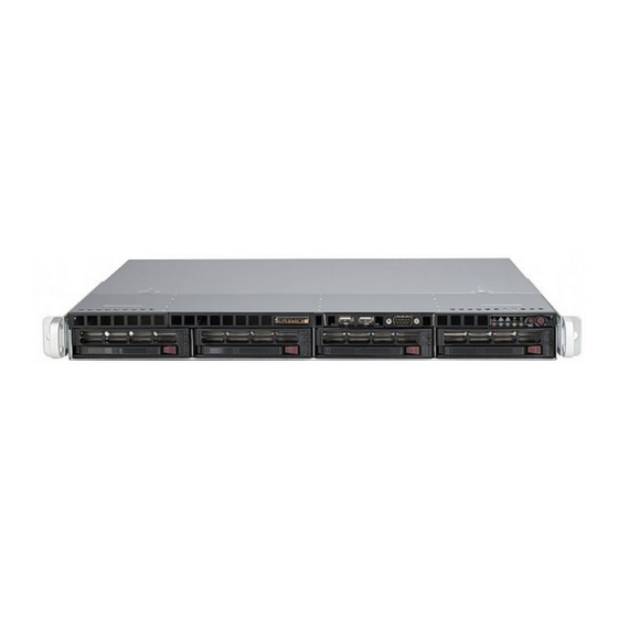
- Page 1 UPER ® 5017C-MTF UPER ERVER 5017C-MTRF UPER ERVER USER’S MANUAL...
- Page 2 The information in this User’s Manual has been carefully reviewed and is believed to be accurate. The vendor assumes no responsibility for any inaccuracies that may be contained in this document, makes no commitment to update or to keep current the information in this manual, or to notify any person or organization of the updates.
-
Page 3: About This Manual
Preface About This Manual This manual is written for professional system integrators and PC technicians. It provides information for the installation and use of the SuperServer 5017C-MTF/ 5017C-MTRF. Installation and maintenance should be performed by experienced technicians only. The SuperServer 5017C-MTF/5017C-MTRF is a high-end server based on the SC- 813MTQ-350B/SC813MTQ-R400B 1U rackmount chassis and the Super X9SCL-F single processor serverboard. - Page 4 UPER ERVER 5017C-MTF/5017C-MTRF User's Manual Chapter 4: System Safety You should thoroughly familiarize yourself with this chapter for a general overview of safety precautions that should be followed when installing and servicing the SuperServer 5017C-MTF/5017C-MTRF. Chapter 5: Advanced Serverboard Setup Chapter 5 provides detailed information on the X9SCL-F serverboard, including the locations and functions of connections, headers and jumpers.
- Page 5 Preface Notes...
-
Page 6: Table Of Contents
UPER ERVER 5017C-MTF/5017C-MTRF User's Manual Table of Contents Chapter 1 Introduction Overview ......................1-1 Motherboard Features ..................1-2 Processors ...................... 1-2 Memory ......................1-2 Serial ATA ......................1-2 I/O Ports ......................1-2 Graphics Controller ..................1-2 Server Chassis Features ................1-3 System Power .................... - Page 7 Table of Contents Chapter 3 System Interface Overview ......................3-1 Control Panel Buttons ..................3-1 Reset ....................... 3-1 Power ......................3-1 Control Panel LEDs ..................3-2 Overheat/Fan Fail ................... 3-2 NIC2 ........................ 3-2 NIC1 ........................ 3-2 HDD ......................... 3-2 Power ......................3-3 Hard Drive Carrier LEDs .................
- Page 8 UPER ERVER 5017C-MTF/5017C-MTRF User's Manual Supero Doctor III ................... 5-24 Chapter 6 Advanced Chassis Setup Static-Sensitive Devices .................. 6-1 Precautions ..................... 6-1 Unpacking ....................... 6-1 Control Panel ....................6-2 System Fans ....................6-3 Drive Bay Installation/Removal ............... 6-3 Removing the Front Bezel ................6-3 SATA Drive Installation ..................
-
Page 9: Chapter 1 Introduction
Chapter 1 Introduction Overview The SuperServer 5017C-MTF/5017C-MTRF is a high-end server comprised of two main subsystems: the SC813MTQ-350B/SC813MTQ-R400B 1U server chassis and the X9SCL-F single processor motherboard. Please refer to our web site for information on operating systems that have been certifi ed for use with the system (www.supermicro.com). -
Page 10: Motherboard Features
ERVER 5017C-MTF/5017C-MTRF User's Manual Motherboard Features At the heart of the SuperServer 5017C-MTF/5017C-MTRF lies the X9SCL-F, a single processor motherboard based on Intel's C202 chipset. Below are the main features of the X9SCL-F (see Figure 1-1 for a block diagram of the chipset). -
Page 11: Server Chassis Features
The following is a general outline of the main features of the SC813MTQ chassis. System Power When confi gured as a SuperServer 5017C-MTF, the SC813MTQ chassis includes a single 350W power supply. When confi gured as a SuperServer 5017C-MTRF, the SC813MTQ chassis includes a redundant 400W power supply. -
Page 12: System Block Diagram
UPER ERVER 5017C-MTF/5017C-MTRF User's Manual Figure 1-1. Intel C200 Chipset: System Block Diagram Note: This is a general block diagram. Please see Chapter 5 for details. DIMM1 DDR3 (CHA) DIMM2(Far) 1333/1066MHz PCIe2.0_x8 PCIe x8 Slot (Slot 7) 4 UDIMM 5.0Gb... -
Page 13: Contacting Supermicro
Chapter 1: Introduction Contacting Supermicro Headquarters Address: Super Micro Computer, Inc. 980 Rock Ave. San Jose, CA 95131 U.S.A. Tel: +1 (408) 503-8000 Fax: +1 (408) 503-8008 Email: marketing@supermicro.com (General Information) support@supermicro.com (Technical Support) Web Site: www.supermicro.com Europe Address: Super Micro Computer B.V. Het Sterrenbeeld 28, 5215 ML 's-Hertogenbosch, The Netherlands Tel:... - Page 14 UPER ERVER 5017C-MTF/5017C-MTRF User's Manual Notes...
-
Page 15: Chapter 2 Server Installation
MTF/5017C-MTRF up and running. Following the steps in the order given should en- able you to have the system operational within a minimal amount of time. This quick setup assumes that your 5017C-MTF/5017C-MTRF system has come to you with the processor and memory preinstalled. If your system is not already fully integrated with a motherboard, processor, system memory etc., please turn to the chapter or... -
Page 16: Rack Precautions
UPER ERVER 5017C-MTF/5017C-MTRF User's Manual installation only in a Restricted Access Location (dedicated equipment rooms, service closets and the like). • This product is not suitable for use with visual display work place devices acccording to §2 of the the German Ordinance for Work with Visual Display Units. -
Page 17: Rack Mounting Considerations
Chapter 2: Server Installation Rack Mounting Considerations Ambient Operating Temperature If installed in a closed or multi-unit rack assembly, the ambient operating tempera- ture of the rack environment may be greater than the ambient temperature of the room. Therefore, consideration should be given to installing the equipment in an environment compatible with the manufacturer’s maximum rated ambient tempera- ture (Tmra). -
Page 18: Installing The System Into A Rack
Identifying the Sections of the Rack Rails You may have received rack rail hardware with the SuperServer 5017C-MTF/5017C- MTRF. (Two front inner rails should already be attached to the chassis.) This hardware consists of two rear inner rails that secure to the chassis, one on each side just behind the preinstalled front inner rails. -
Page 19: Installing The Rack Rails
Figure 2-1. Installing Rear Inner Chassis Rails Installing the Rack Rails Determine where you want to place the SuperServer 5017C-MTF/5017C-MTRF in the rack (see Rack and Server Precautions in Section 2-3). Position the chassis rail guides at the desired location in the rack, keeping the sliding rail guide facing the inside of the rack. -
Page 20: Installing The Server Into The Rack
UPER ERVER 5017C-MTF/5017C-MTRF User's Manual Installing the Server into the Rack You should now have rails attached to both the chassis and the rack unit. The next step is to install the server into the rack. Do this by lining up the rear of the chassis rails with the front of the rack rails. -
Page 21: Installing The Server Into A Telco Rack
Chapter 2: Server Installation Installing the Server into a Telco Rack To install the SuperServer 5017C-MTF/5017C-MTRF into a Telco type rack, use two L-shaped brackets on either side of the chassis (four total). First, determine how far the server will extend out the front of the rack. Larger chassis should be positioned to balance the weight between front and back. -
Page 22: Checking The Motherboard Setup
UPER ERVER 5017C-MTF/5017C-MTRF User's Manual Checking the Motherboard Setup After you install the 5017C-MTF/5017C-MTRF in the rack, you will need to open the unit to make sure the motherboard is properly installed and all the connections have been made. Accessing the Inside of the System Grasp the two handles on either side and pull the unit straight out until it locks (you will hear a "click"). -
Page 23: Checking The Drive Bay Setup
Chapter 2: Server Installation Figure 2-4. Accessing the Inside of the SuperServer 5017C-MTF/5017C-MTRF Release buttons Checking the Drive Bay Setup Next, you should check to make sure the peripheral drives and the SATA drives and their backplane have been properly installed and all essential connections have been made. - Page 24 UPER ERVER 5017C-MTF/5017C-MTRF User's Manual Also note that all power and data cables have been routed in such a way that they do not block the airfl ow generated by the fans. Providing Power Plug the power cord from the power supply unit into a high-quality power strip that offers protection from electrical noise and power surges.
-
Page 25: Chapter 3 System Interface
Chapter 3: System Interface Chapter 3 System Interface Overview There are several LEDs on the control panel as well as others on the hard drive carriers to keep you constantly informed of the overall status of the system as well as the activity and health of specifi... -
Page 26: Control Panel Leds
NIC2 Indicates network activity on LAN2 when fl ashing. NIC1 Indicates network activity on LAN1 when fl ashing. Channel activity for all HDDs. This light indicates DVD-ROM/hard drive activity on the 5017C-MTF/5017C-MTRF when fl ashing. -
Page 27: Power
Chapter 3: System Interface Power Indicates power is being supplied to the system's power supply units. This LED should normally be illuminated when the system is operating. Hard Drive Carrier LEDs Each drive carrier has two LEDs. • Green: When illuminated, the green LED on the drive carrier indicates drive activity. - Page 28 UPER ERVER 5017C-MTF/5017C-MTRF User's Manual Notes...
-
Page 29: Chapter 4 System Safety
System Safety Electrical Safety Precautions Basic electrical safety precautions should be followed to protect yourself from harm and the SuperServer 5017C-MTF/5017C-MTRF from damage: • Be aware of the locations of the power on/off switch on the chassis as well as the room's emergency power-off switch, disconnection switch or electrical outlet. -
Page 30: General Safety Precautions
General Safety Precautions Follow these rules to ensure general safety: • Keep the area around the 5017C-MTF/5017C-MTRF clean and free of clutter. • The 5017C-MTF/5017C-MTRF weighs approximately 38 lbs (~17.3 kg) when fully loaded. When lifting the system, two people at either end should lift slowly with their feet spread out to distribute the weight. -
Page 31: Esd Precautions
Chapter 4: System Safety • Remove any jewelry or metal objects from your body, which are excellent metal conductors that can create short circuits and harm you if they come into contact with printed circuit boards or areas where power is present. •... -
Page 32: Operating Precautions
UPER ERVER 5017C-MTF/5017C-MTRF User's Manual Operating Precautions Care must be taken to assure that the chassis cover is in place when the 5017C- MTF/5017C-MTRF is operating to assure proper cooling. Out of warranty damage to the system can occur if this practice is not strictly followed. -
Page 33: Chapter 5 Advanced Motherboard Setup
Chapter 5: Advanced Motherboard Setup Chapter 5 Advanced Motherboard Setup This chapter covers the steps required to install processors and heatsinks to the X9SCL-F motherboard, connect the data and power cables and install add-on cards. All motherboard jumpers and connections are described and a layout and quick reference chart are included in this chapter. -
Page 34: Processor And Heatsink Installation
UPER ERVER 5017C-MTF/5017C-MTRF User's Manual Processor and Heatsink Installation Notes: • Always connect the power cord last and always remove it before adding, re- moving or changing any hardware components. Make sure that you install the processor into the CPU socket before you install the CPU heatsink. - Page 35 Chapter 5: Advanced Motherboard Setup Use your thumb and your index fi nger to hold the CPU at the top center edge and the bottom center edge of the CPU. Align the CPU key (the semi-circle cutouts) against the socket keys. Once aligned, carefully lower the CPU straight down to the socket.
-
Page 36: Installing A Passive Cpu Heatsink
UPER ERVER 5017C-MTF/5017C-MTRF User's Manual CPU properly installed Load lever locked into place. Warning: The CPU will only seat inside the socket in one direction. Make sure it is properly inserted before closing the load plate. If it doesn't close properly, do not force it as it may damage your CPU. - Page 37 Chapter 5: Advanced Motherboard Setup Figure 5-3. Installing the Heatsink Once the CPU is loose, remove the it from the CPU socket. Clean the surface of the CPU and the heatsink, removing the used thermal grease. Reapply the proper amount of thermal grease on the surface before re-installing the CPU and the heatsink.
-
Page 38: Connecting Cables
UPER ERVER 5017C-MTF/5017C-MTRF User's Manual Connecting Cables Now that the processors are installed, the next step is to connect the cables to the motherboard. These include the data (ribbon) cables for the peripherals and control panel and the power cables. -
Page 39: I/O Ports
Chapter 5: Advanced Motherboard Setup All JF1 wires have been bundled into single keyed ribbon cable to simplify their con- nection. Connect one end of this cable to JF1 and the other end to the Control Panel printed circuit board, located just behind the system status LEDs in the chassis. See the Connector Defi... -
Page 40: Installing Memory
UPER ERVER 5017C-MTF/5017C-MTRF User's Manual Installing Memory Note: Check the Supermicro web site for recommended memory modules. CAUTION Exercise extreme care when installing or removing DIMM modules to prevent any possible damage. Installing DIMMs Insert the desired number of DIMMs into the memory slots, starting with slots DIMM1A. - Page 41 Chapter 5: Advanced Motherboard Setup Figure 5-3. Installing DIMM into Slot Notch Notch To Install: Insert module vertically and press down until it snaps into place. Pay attention to the alignment notch at Front View the bottom. To Remove: Note: Notch should align Use your thumbs to with the receptive key gently push the release...
-
Page 42: Adding Pci Cards
UPER ERVER 5017C-MTF/5017C-MTRF User's Manual Adding PCI Cards PCI Expansion Slots One riser card is used to support a PCI expansion (add-on) card in the system. The SC813MTQ-350B chassis can accommodate one standard size (full height full length) PCI expansion card. When viewed from the chassis front, the card installs to the left rear of the system. -
Page 43: Motherboard Details
Chapter 5: Advanced Motherboard Setup Motherboard Details Figure 5-4. SUPER X9SCL-F Layout KB/MOUSE JPI2C FP CTRL JPW2 JPW1 JPUSB1 DIMM2B FAN1 DIMM1B DDR3 1066/1333 UDIMM required DIMM2A JSPK JTPM DIMM1A SPKR1 S I/O FAN2 Fan4 Socket H2 82574L LGA 1155 X9SCM/X9SCL(-F) 82579 Rev.1.0... - Page 44 UPER ERVER 5017C-MTF/5017C-MTRF User's Manual Headers/Connectors Number Connector Description Onboard Battery 4,16 COM1/COM2 COM1/2 Serial Port/Header BIOS SPI BIOS 42,38,37,7,30 Fans 1~4, Fan A System/CPU Fan Headers SPI Programming (internal use) Front Panel Control Header Chassis Intrusion Header JLED1 Power LED Indicator Header...
-
Page 45: Connector Defi Nitions
Chapter 5: Advanced Motherboard Setup Connector Defi nitions ATX Power 24-pin Connector Pin Defi nitions (JPW1) Pin# Defi nition Pin # Defi nition ATX Power Connector +3.3V +3.3V A 24-pin main power connector is located -12V +3.3V at JPW1. This power connector meet the SSI EPS 12V specifi... - Page 46 UPER ERVER 5017C-MTF/5017C-MTRF User's Manual NIC1/NIC2 (LAN1/LAN2) The NIC (Network Interface Controller) LED connection for LAN port 1 is located LAN1/LAN2 LED on pins 11 and 12 of JF1, and the LED Pin Defi nitions (JF1) connection for LAN Port 2 is on Pins 9 Pin# Defi...
- Page 47 Chapter 5: Advanced Motherboard Setup Back Panel USB0/1 Pin Defi nitions Universal Serial Bus (USB) Pin# Defi nition Pin# Defi nition Two Universal Serial Bus ports (USB 0/1) are located on the I/O backpanel and an USB_PN1 USB_PN0 additional six USB ports in three head- USB_PP1 USB_PP0 ers, USB2/3, 4/5, 12/13 provide front/...
- Page 48 UPER ERVER 5017C-MTF/5017C-MTRF User's Manual Fan Headers The X9SCL-F has fi ve fan headers (Fan1 ~ Fan4 and FanA). These are all 4-pin fan headers, however pins 1-3 are backward Fan Header compatible with traditional 3-pin fans. Pin Defi nitions...
- Page 49 Chapter 5: Advanced Motherboard Setup Trusted Platform Module Header Trusted Platform Module Header Pin Defi nitions This header is used to connect a Trusted Pin # Defi nition Pin # Defi nition Platform Module (TPM), available sepa- LCLK rately from a third-party vendor. A TPM is LFRAME No Pin a security device that allows encryption...
- Page 50 UPER ERVER 5017C-MTF/5017C-MTRF User's Manual T-SGPIO 0/1 Headers Serial_Link-SGPIO Pin Defi nitions Two T-SGPIO (Serial-Link General Pur- Pin# Defi nition Defi nition pose Input/Output) headers are located near the SATA connectors on the moth- Ground DATA Out erboard. These headers are used to com-...
-
Page 51: Jumper Settings
Chapter 5: Advanced Motherboard Setup Jumper Settings Explanation of Jumpers To modify the operation of the mother- board, jumpers can be used to choose Connector between optional settings. Jumpers cre- Pins ate shorts between two pins to change the function of the connector. Pin 1 is Jumper identifi... - Page 52 UPER ERVER 5017C-MTF/5017C-MTRF User's Manual PCI Slot SMB Enable PCI Slot SMB Enable/Disable Jumper Settings Use Jumpers JI C1/JI C2 to enable PCI Jumper Setting Defi nition SMB (System Management Bus) support Closed Enabled to improve system management for the...
-
Page 53: 5-10 Onboard Indicators
Chapter 5: Advanced Motherboard Setup 5-10 Onboard Indicators LAN1/LAN2 LEDs LAN LED The Ethernet ports (located beside the Connection Speed Indicator VGA port) have two LEDs. On each Giga- LED State Defi nition bit LAN port, the yellow LED indicates No connection or 10 Mb/s activity when blinking while the other LED Green... -
Page 54: 5-11 Sata Drive Connections
UPER ERVER 5017C-MTF/5017C-MTRF User's Manual 5-11 SATA Drive Connections SATA Port Pin Defi nitions (SATA0 ~ SATA5) Pin # Defi nition SATA Ports Ground Six Serial ATA (SATA) ports (I-SATA 0~5) are located on the motherboard. See the table on the right for pin defi nitions for the Ground onboard SATA ports. -
Page 55: 5-12 Installing Drivers
Chapter 5: Advanced Motherboard Setup 5-12 Installing Drivers After all the hardware and operating system have been installed, you need to install certain drivers. The necessary drivers are all included on the Supermicro CD that came packaged with your motherboard. After inserting this CD into your CD-ROM drive, the display shown in Figure 5-4 should appear. -
Page 56: Supero Doctor Iii
ERVER 5017C-MTF/5017C-MTRF User's Manual Supero Doctor III The Supero Doctor III program is a Web base management tool that supports remote management capability. It includes Remote and Local Management tools. The local management is called SD III Client. The Supero Doctor III program included on the CDROM that came with your motherboard allows you to monitor the environment and operations of your system. - Page 57 Chapter 5: Advanced Motherboard Setup Supero Doctor III Interface Display Screen (Remote Control) Note: SD III Software Revision 1.0 can be downloaded from our Web Site at: ftp:// ftp.supermicro.com/utility/Supero_Doctor_III/. You can also download SDIII User's Guide at: http://www.supermicro.com/manuals/other/SDIII_User_Guide.pdf. For Linux, we will still recommend Supero Doctor II.
- Page 58 UPER ERVER 5017C-MTF/5017C-MTRF User's Manual Notes 5-26...
-
Page 59: Chapter 6 Advanced Chassis Setup
Chapter 6: Advanced Chassis Setup Chapter 6 Advanced Chassis Setup This chapter covers the steps required to install components and perform mainte- nance on the SC813MTQ chassis. For component installation, follow the steps in the order given to eliminate the most common problems encountered. If some steps are unnecessary, skip ahead to the step that follows. -
Page 60: Control Panel
UPER ERVER 5017C-MTF/5017C-MTRF User's Manual Figure 6-1. Chassis Front View USB Ports COM2 Port Control Panel SATA Drives (4) Figure 6-2. Chassis Rear View Power Supply* PCI Expansion Slot Dedicated IPMI Port Mouse Port Keyboard Port USB Ports COM1 Port... -
Page 61: System Fans
Chapter 6: Advanced Chassis Setup System Fans Four 4-cm high-performance fans provide the cooling for the SuperServer 5017C- MTF/5017C-MTRF. The chassis includes air seals under the fans and at the chassis cross section, which separates the drive bay area from the serverboard area of the chassis to promote better airfl... -
Page 62: Sata Drive Installation
Proceed to the "DVD-ROM Drive Installation" section in this chapter for instructions. Note that only a "slim" DVD-ROM drive will fi t into the 5017C-MTF/5017C-MTRF. Use caution when working around the SATA backplane. Do not touch the backplane with any metal objects and make sure no ribbon cables touch the backplane. -
Page 63: Sata Backplane
Chapter 6: Advanced Chassis Setup Figure 6-4. Mounting a Drive in a Carrier SATA Backplane The SATA drives plug into a backplane that provides power, drive ID and bus termi- nation. A RAID controller can be used with the backplane to provide data security for the drives. - Page 64 DVD-ROM Drive Installation The top cover of the chassis must be opened to gain full access to the DVD-ROM drive bay. The 5017C-MTF/5017C-MTRF accomodates only slim DVD-ROM drives. Side mounting brackets are needed to mount a slim DVD-ROM drive into the 5017C- MTF/5017C-MTRF server.You must power down the system before installing or...
-
Page 65: Power Supply
Chapter 6: Advanced Chassis Setup Power Supply The SuperServer 5017C-MTF has a single 350 watt power supply. This power sup- ply has the capability of operating at 100 - 240 input volts. Depress the main power button on the front of the chassis and then unplug the AC power cord to completely remove power from the system before removing the power supply. - Page 66 UPER ERVER 5017C-MTF/5017C-MTRF User's Manual The SuperServer 5017C-MTRF has a 400 watt redundant power supply consisting of two power modules. Each power supply module has an auto-switching capabil- ity, which enables it to automatically sense and operate at a 100V - 240V input voltage.
-
Page 67: Chapter 7 Bios
Chapter 7: BIOS Chapter 7 BIOS Introduction This chapter describes the AMI BIOS Setup Utility for the X9SCL-F. The AMI ROM BIOS is stored in a Flash EEPROM and can be easily updated. This chapter de- scribes the basic navigation of the AMI BIOS Setup Utility setup screens. Note: For instructions on BIOS recovery, please refer to the instruction guide posted at http://www.supermicro.com/support/manuals/. -
Page 68: Main Setup
UPER ERVER 5017C-MTF/5017C-MTRF User's Manual How to Start the Setup Utility Normally, the only visible Power-On Self-Test (POST) routine is the memory test. As the memory is being tested, press the <Delete> key to enter the main menu of the AMI BIOS Setup Utility. From the main menu, you can access the other setup screens. - Page 69 Chapter 7: BIOS System Overview: The following BIOS information will be displayed: System Time/System Date Use this option to change the system time and date. Highlight System Time or Sys- tem Date using the arrow keys. Enter new values through the keyboard. Press the <Tab>...
-
Page 70: Advanced Setup Confi Gurations
UPER ERVER 5017C-MTF/5017C-MTRF User's Manual Advanced Setup Confi gurations Use the arrow keys to select Boot Setup and hit <Enter> to access the submenu items: BIOS SETUP UTILTY Main Advanced Event Logs IPMI Boot Security Exit System Boot Feature Boot Feature Setting. - Page 71 Chapter 7: BIOS 19 at boot and allow the drives that are attached to these host adaptors to function as bootable disks. If this item is set to Disabled, the ROM BIOS of the host adap- tors will not capture Interrupt 19, and the drives attached to these adaptors will not function as bootable devices.
- Page 72 UPER ERVER 5017C-MTF/5017C-MTRF User's Manual Adjacent Cache Line Prefetch (Available when supported by the CPU) The CPU fetches the cache line for 64 bytes if this option is set to Disabled. The CPU fetches both cache lines for 128 bytes as comprised if Enabled.
- Page 73 Chapter 7: BIOS P-STATE Coordination This feature selects the type of coordination for the P-State of the processor. P-State is a processor operational state that reduces the processor's voltage and frequency. This makes the processor more energy effi icient, resulting in further gains.
- Page 74 UPER ERVER 5017C-MTF/5017C-MTRF User's Manual North Bridge Confi guration This item displays the current North Bridge Revision. VT-d Select Enabled to enable Intel's Virtualization Technology support for Direct I/O VT-d by reporting the I/O device assignments to VMM through the DMAR ACPI Tables. This feature offers fully-protected I/O resource- sharing across the Intel platforms, providing the user with greater reliabil- ity, security and availability in networking and data-sharing.
- Page 75 Chapter 7: BIOS Wake on LAN from S5 Select Enabled to enable the capabiltiy to 'wake-up' the system from the S5 power state (Soft Off State) through the Ethernet controller. The set- tings are Enabled and Disabled. Legacy USB Support This feature enables support for legacy USB devices.
- Page 76 UPER ERVER 5017C-MTF/5017C-MTRF User's Manual Aggressive Link Power Management This feature Enables or Disables Agressive Link Power Management support for Cougar Point B0 stepping and later. The options are Enabled and Disabled. SATA Port0~Port5 This item displays the information detected on the installed SATA drives on the particular SATA port.
- Page 77 Chapter 7: BIOS PCI Latency Timer This feature sets the latency Timer of each PCI device installed on a PCI bus. Select 64 to set the PCI latency to 64 PCI clock cycles. The options are 32, 64, 96, 128, 160, 192, 224 and 248.
- Page 78 UPER ERVER 5017C-MTF/5017C-MTRF User's Manual Serial Port 2 Mode Use this feature to confi gure Serial Port 2 mode. The options are Normal, IrDA and ASK IR. IrDA (Infrared Data) is an industry standard for remote control devices. ASK IR (Amplitude Shifted Keying Infrared) is a protocol compatible with Sharp® branded PDAs and other infrared devices.
- Page 79 Chapter 7: BIOS Parity: None, Even, Odd, Mark, or Space Stop Bits: 1 or 2 Hardware Health Confi guration Fan Speed Control Mode This feature allows the user to decide how the system controls the speeds of the onboard fans. The CPU temperature and the fan speed are correlative. When the CPU on-die temperature increases, the fan speed will also increase for effective system cooling.
- Page 80 UPER ERVER 5017C-MTF/5017C-MTRF User's Manual High – The processor is running hot. This is a ‘caution’ level since the CPU’s ‘Temperature Tolerance’ has been reached (or has been exceeded) and may activate an overheat alarm: The information provided above is for your reference only. For more information on thermal management, please refer to Intel’s Web site at www.Intel.com.
-
Page 81: Event Logs
Chapter 7: BIOS Event Logs BIOS SETUP UTILTY Main Advanced Event Logs IPMI Boot Security Exit Change Smbios Event Log Settings Press <Enter> to change the Smbios Event Log View Smbios Event Log configuration. View System Event Log Select Screen Select Item Enter: Select... -
Page 82: Ipmi Confi Guration
UPER ERVER 5017C-MTF/5017C-MTRF User's Manual IPMI Confi guration Intelligent Platform Management Interface (IPMI) is a set of common interfaces that IT administrators can use to monitor system health and to manage the system as a whole. For more information on the IPMI specifi cations, please visit Intel's website at www.intel.com. - Page 83 Chapter 7: BIOS SEL Components - Change this item to enable or disable all features of System Event Logging. The options are Enabled and Disabled. When Enabled, the following can be confi gured: Erase SEL - This option erases all logged SEL events. The options are No, Yes, On Next reset and Yes, On Every reset.
-
Page 84: Boot Settings
UPER ERVER 5017C-MTF/5017C-MTRF User's Manual Boot Settings BIOS SETUP UTILTY Main Advanced Event Logs IPMI Boot Security Exit Setup Prompt Timeout Number of seconds to wait for setup Boot Options Priority activation key. 65535 (0xFFFF) means indefinite waiting. Select Screen... -
Page 85: Security Settings
Chapter 7: BIOS Security Settings BIOS SETUP UTILTY Main Advanced Event Logs IPMI Boot Security Exit Password Description Set Setup Administrator Pasword. If ONLY the administrator’s password is set, then this only limits access to Setup and is only asked for when entering Setup. If ONLY the User’s password is set, then this is a power on password and must be entered to boot or enter Setup. -
Page 86: Exit Options
UPER ERVER 5017C-MTF/5017C-MTRF User's Manual Exit Options BIOS SETUP UTILTY Main Advanced Event Logs IPMI Boot Security Exit Save Changes and Exit Exit system setup after Discard Changes and Exit saving the changes. Discard Changes Restore Defaults Save as User Defaults... - Page 87 Chapter 7: BIOS Save As User Defaults To set this feature, select Save as User Defaults from the Exit menu and press <En- ter>. This enables the user to save any changes to the BIOS setup for future use Restore User Defaults To set this feature, select Restore User Defaults from the Exit menu and press <En- ter>.
- Page 88 UPER ERVER 5017C-MTF/5017C-MTRF User's Manual Notes 7-22...
-
Page 89: Appendix A Bios Error Beep Codes
Appendix A: POST Error Beep Codes Appendix A BIOS Error Beep Codes During the POST (Power-On Self-Test) routines, which are performed each time the system is powered on, errors may occur. Non-fatal errors are those which, in most cases, allow the system to continue with bootup. - Page 90 UPER ERVER 5017C-MTF/5017C-MTRF User's Manual Notes...
-
Page 91: Appendix B System Specifi Cations
Appendix B: System Specifi cations Appendix B System Specifi cations Processors ® ® Single Intel Xeon E3-1200 Series processor or a Core i3-2100 Series processor in an LGA1155 socket Note: Please refer to our web site for a complete listing of supported processors. Chipset Intel C202 BIOS... - Page 92 UPER ERVER 5017C-MTF/5017C-MTRF User's Manual Chassis SC813MTQ Form Factor: 1U rackmount Dimensions: (WxHxD) 17.2 x 1.7 x 19.85 in. (437 x 43 x 504 mm) Weight Gross Weight: 38 lbs. (17.3 kg.) System Cooling Four 4-cm high performance fans One air shroud...
-
Page 93: Regulatory Compliance
Appendix B: System Specifi cations Regulatory Compliance Electromagnetic Emissions: FCC Class A, EN 55022 Class A, EN 61000-3-2/-3-3, CISPR 22 Class A Electromagnetic Immunity: EN 55024/CISPR 24, (EN 61000-4-2, EN 61000-4-3, EN 61000-4-4, EN 61000-4-5, EN 61000-4-6, EN 61000-4-8, EN 61000-4-11) Safety: EN 60950/IEC 60950-Compliant, UL Listed (USA), CUL Listed (Canada), TUV Certifi... - Page 94 UPER ERVER 5017C-MTF/5017C-MTRF User's Manual Notes...
Need help?
Do you have a question about the SUPERSERVER 5017C-MTF and is the answer not in the manual?
Questions and answers