Table of Contents
Advertisement
Quick Links
Advertisement
Table of Contents

Related Manuals for Supero SUPERSERVER 5017K-N6


Summary of Contents for Supero SUPERSERVER 5017K-N6
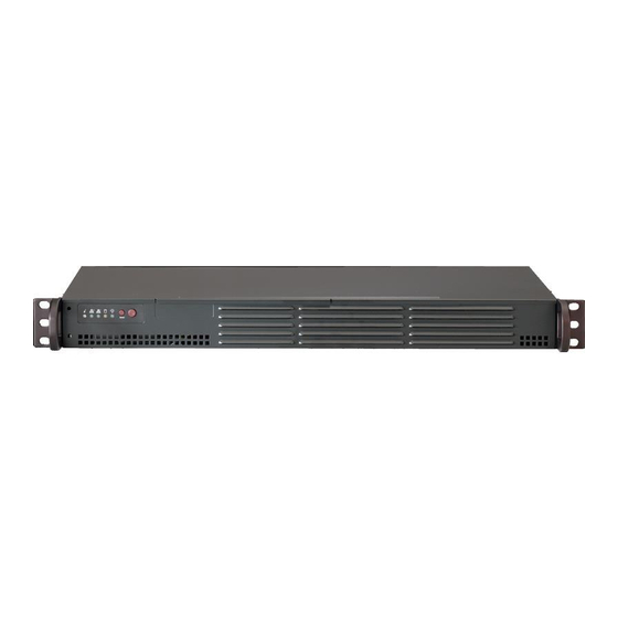
- Page 1 UPER ® UPER ERVER 5017K-N6 USER’S MANUAL...
- Page 2 The information in this User’s Manual has been carefully reviewed and is believed to be accurate. The vendor assumes no responsibility for any inaccuracies that may be contained in this document, makes no commitment to update or to keep current the information in this manual, or to notify any person or organization of the updates.
- Page 3 SuperServer 5017K-N6. Installation and maintainance should be performed by experienced technicians only. The SuperServer 5017K-N6 is a high-end server based on the SC504-203B rack- mountable chassis and the X9SKV-B915 single processor motherboard.
- Page 4 UPER ERVER 5017K-N6 User's Manual Chapter 5: Advanced Motherboard Setup Chapter 5 provides detailed information on the X9SKV-B915 motherboard, includ- ing the locations and functions of connections, headers and jumpers. Refer to this chapter when adding or removing processors or main memory and when reconfi g- uring the motherboard.
- Page 5 Preface Notes...
-
Page 6: Table Of Contents
UPER ERVER 5017K-N6 User's Manual Table of Contents Chapter 1 Introduction Overview ......................1-1 Motherboard Features ..................1-2 Processor ......................1-2 Memory ......................1-2 Serial ATA ......................1-2 PCI Expansion Slots ..................1-2 Rear I/O Ports ....................1-2 Server Chassis Features ................1-3 System Power .................... - Page 7 Table of Contents Control Panel LEDs ..................3-2 Power Fail ....................... 3-2 Information LED ....................3-2 NIC1 ........................ 3-2 NIC2 ........................ 3-3 HDD ......................... 3-3 Power ......................3-3 Chapter 4 Standardized Warning Statements for AC Systems About Standardized Warning Statements ............4-1 Warning Defi...
- Page 8 UPER ERVER 5017K-N6 User's Manual Connector Defi nitions ..................5-8 Jumper Settings .................... 5-14 5-10 Onboard Indicators ..................5-16 5-11 SATA Ports ....................5-17 5-12 Installing Software ..................5-18 SuperDoctor® 5 .................... 5-19 5-13 Onboard Battery .................... 5-20 Chapter 6 Advanced Chassis Setup Static-Sensitive Devices ..................
-
Page 9: Chapter 1 Introduction
Chapter 1 Introduction Overview The SuperServer 5017K-N6 is a mini server comprised of two main subsystems: the SC504-203B 1U chassis and the X9SKV-B915 single processor motherboard. Please refer to our web site for information on operating systems that have been certifi... -
Page 10: Motherboard Features
ERVER 5017K-N6 User's Manual Motherboard Features The SuperServer 5017K-N6 is built around the X9SKV-B915, a single processor motherboard based on the Intel 8903CC chipset and designed to provide maximum performance. Below are the main features of the X9SKV-B915. (See Figure 1-1 for a block diagram of the chipset). -
Page 11: Server Chassis Features
Chapter 1: Introduction Server Chassis Features The SC504-203B is an mini-ITX form factor chassis designed to be used in a 1U rackmount confi guration. The following is a general outline of the main features of the SC504-203B server chassis. System Power The SC504-203B features a single 200W power supply. - Page 12 UPER ERVER 5017K-N6 User's Manual Figure 1-1. Intel 8903CC Chipset: System Block Diagram Note: This is a general block diagram. Please see Chapter 5 for details. J P S O T 1 c o n t r o l C h a n n e l A J P C I E 1 P C I E 2 .
-
Page 13: Contacting Supermicro
Chapter 1: Introduction Contacting Supermicro Headquarters Address: Super Micro Computer, Inc. 980 Rock Ave. San Jose, CA 95131 U.S.A. Tel: +1 (408) 503-8000 Fax: +1 (408) 503-8008 Email: marketing@supermicro.com (General Information) support@supermicro.com (Technical Support) Web Site: www.supermicro.com Europe Address: Super Micro Computer B.V. Het Sterrenbeeld 28, 5215 ML 's-Hertogenbosch, The Netherlands Tel:... - Page 14 UPER ERVER 5017K-N6 User's Manual Notes...
-
Page 15: Chapter 2 Server Installation
Unpacking the System You should inspect the box the SuperServer 5017K-N6 was shipped in and note if it was damaged in any way. If the server itself shows damage you should fi le a damage claim with the carrier who delivered it. -
Page 16: Warnings And Precautions
UPER ERVER 5017K-N6 User's Manual • This product is not suitable for use with visual display work place devices acccording to §2 of the the German Ordinance for Work with Visual Display Units. Warnings and Precautions Rack Precautions • Ensure that the leveling jacks on the bottom of the rack are fully extended to the fl... -
Page 17: Rack Mounting Considerations
Chapter 2: Server Installation Rack Mounting Considerations Ambient Operating Temperature If installed in a closed or multi-unit rack assembly, the ambient operating tempera- ture of the rack environment may be greater than the ambient temperature of the room. Therefore, consideration should be given to installing the equipment in an environment compatible with the manufacturer’s maximum rated ambient tempera- ture (Tmra). -
Page 18: Installing The System Into A Rack
UPER ERVER 5017K-N6 User's Manual Installing the System into a Rack This section provides information on installing the SC504 chassis into a rack unit. There are a variety of rack units on the market, which may mean the assembly procedure will differ slightly. You should also refer to the installation instructions that came with the rack unit you are using. -
Page 19: Telco Rack
Chapter 2: Server Installation Telco Rack The SC504 supports Telco Rack installation. The SC504 chassis' compact design allows it to be installed into a Telco rack without the use of rails. Figure 2-2. Installing the Chassis into a Telco Rack Installing the Chassis into a Telco Rack 1. - Page 20 UPER ERVER 5017K-N6 User's Manual Notes...
-
Page 21: Chapter 3 System Interface
Chapter 3: System Interface Chapter 3 System Interface Overview There are several LEDs on the control panel as well as others on the drive carriers to keep you constantly informed of the overall status of the system and the activ- ity and health of specifi... -
Page 22: Control Panel Leds
SUPERSERVER 5017K-N6 User's Manual Control Panel LEDs The control panel located on the front of the chassis has fi ve LEDs. These LEDs provide you with critical information related to different parts of the system. This section explains what each LED indicates when illuminated and any corrective ac- tion you may need to take. -
Page 23: Nic2
Chapter 3: System Interface NIC2 Indicates network activity on the LAN6 port when fl ashing. On the SuperServer 5017K-N6, this LED indicates SATA drive activity when fl ashing. Power Indicates power is being supplied to the system's power supply units. This LED... - Page 24 SUPERSERVER 5017K-N6 User's Manual Notes...
-
Page 25: Chapter 4 Standardized Warning Statements For Ac Systems
Chapter 4: Warning Statements for AC Systems Chapter 4 Standardized Warning Statements for AC Systems About Standardized Warning Statements The following statements are industry standard warnings, provided to warn the user of situations which have the potential for bodily injury. Should you have questions or experience difficulty, contact Supermicro's Technical Support department for assistance. - Page 26 UPER ERVER 5017K-N6 User's Manual Warnung WICHTIGE SICHERHEITSHINWEISE Dieses Warnsymbol bedeutet Gefahr. Sie befi nden sich in einer Situation, die zu Verletzungen führen kann. Machen Sie sich vor der Arbeit mit Geräten mit den Gefahren elektrischer Schaltungen und den üblichen Verfahren zur Vorbeugung vor Unfällen vertraut.
- Page 27 Warning Statements for AC Systems ﺟﺴﺪﻳﺔ ﺍﺻﺎﺑﺔ ﺗﺘﺴﺒﺐ ﻓﻲ ﺣﺎﻟﺔ ﻳﻤﻜﻦ ﺃﻥ ﺍﻧﻚ ﻓﻲ ﺧﻄﺮ ﻳﻌﻨﻲ ﻫﺬﺍ ﺍﻟﺮﻣﺰ !ﺗﺤﺬﻳﺮ ﺍﻟﺪﻭﺍﺋﺮ ﺑﺎﻟﻤﺨﺎﻁﺮ ﺍﻟﻨﺎﺟﻤﺔ ﻋﻦ ﻦ ﻋﻠﻰ ﻋﻠﻢ ، ﻛ ﻣﻌﺪﺍﺕ ﺗﻌﻤﻞ ﻋﻠﻰ ﺃﻱ ﻗﺒﻞ ﺃﻥ ﺍﻟﻜﻬﺮﺑﺎﺋﻴﺔ ﺣﻮﺍﺩﺙ ﺃﻱ ﻭﻗﻮﻉ ﻤﻨﻊ ﻟ ﺍﻟﻮﻗﺎﺋﻴﺔ...
-
Page 28: Installation Instructions
UPER ERVER 5017K-N6 User's Manual Installation Instructions Warning! Read the installation instructions before connecting the system to the power source. 設置手順書 システムを電源に接続する前に、 設置手順書をお読み下さい。 警告 将此系统连接电源前,请先阅读安装说明。 警告 將系統與電源連接前,請先閱讀安裝說明。 Warnung Vor dem Anschließen des Systems an die Stromquelle die Installationsanweisungen lesen. ¡Advertencia! Lea las instrucciones de instalación antes de conectar el sistema a la red de alimentación. -
Page 29: Circuit Breaker
Chapter 4: Warning Statements for AC Systems Circuit Breaker Warning! This product relies on the building's installation for short-circuit (overcurrent) protection. Ensure that the protective device is rated not greater than: 250 V, 20 A. サーキッ ト ・ ブレーカー この製品は、 短絡 (過電流) 保護装置がある建物での設置を前提としています。 保護装置の定格が250 V、... -
Page 30: Power Disconnection Warning
UPER ERVER 5017K-N6 User's Manual 경고! 이 제품은 전원의 단락(과전류)방지에 대해서 전적으로 건물의 관련 설비에 의존합니다. 보호장치의 정격이 반드시 250V(볼트), 20A(암페어)를 초과하지 않도록 해야 합니다. Waarschuwing Dit product is afhankelijk van de kortsluitbeveiliging (overspanning) van uw electrische installatie. Controleer of het beveiligde aparaat niet groter gedimensioneerd is dan 220V, 20A. - Page 31 Chapter 4: Warning Statements for AC Systems ¡Advertencia! El sistema debe ser disconnected de todas las fuentes de energía y del cable eléctrico quitado de los módulos de fuente de alimentación antes de tener acceso el interior del chasis para instalar o para quitar componentes de sistema. Attention Le système doit être débranché...
-
Page 32: Equipment Installation
UPER ERVER 5017K-N6 User's Manual Equipment Installation Warning! Only trained and qualifi ed personnel should be allowed to install, replace, or service this equipment. 機器の設置 トレーニングを受け認定された人だけがこの装置の設置、 交換、 またはサービスを許可 されています。 警告 只有经过培训且具有资格的人员才能进行此设备的安装、更换和维修。 警告 只有經過受訓且具資格人員才可安裝、更換與維修此設備。 Warnung Das Installieren, Ersetzen oder Bedienen dieser Ausrüstung sollte nur geschultem, qualifi... -
Page 33: Restricted Area
Chapter 4: Warning Statements for AC Systems Waarschuwing Deze apparatuur mag alleen worden geïnstalleerd, vervangen of hersteld door geschoold en gekwalifi ceerd personeel. Restricted Area Warning! This unit is intended for installation in restricted access areas. A restricted access area can be accessed only through the use of a special tool, lock and key, or other means of security. -
Page 34: Battery Handling
UPER ERVER 5017K-N6 User's Manual אזור עם גישה מוגבלת !אזהרה יש להתקין את היחידה באזורים שיש בהם הגבלת גישה. הגישה ניתנת בעזרת .('כלי אבטחה בלבד )מפתח, מנעול וכד ﻣﺤﻈﻮﺭﺓ ﻣﻨﺎﻁﻖ ﻟﺘﺮﻛﻴﺒﻬﺎ ﻓﻲ ﻫﺬﻩ ﺍﻟﻮﺣﺪﺓ ﺗﺨﺼﻴﺺ ﺗﻢ ،ﺃﺩﺍﺓ ﺧﺎﺻﺔ ﻣﻦ ﺧﻼﻝ ﺍﺳﺘﺨﺪﺍﻡ ﻓﻘﻂ... - Page 35 Chapter 4: Warning Statements for AC Systems Warnung Bei Einsetzen einer falschen Batterie besteht Explosionsgefahr. Ersetzen Sie die Batterie nur durch den gleichen oder vom Hersteller empfohlenen Batterietyp. Entsorgen Sie die benutzten Batterien nach den Anweisungen des Herstellers. Attention Danger d'explosion si la pile n'est pas remplacée correctement. Ne la remplacer que par une pile de type semblable ou équivalent, recommandée par le fabricant.
-
Page 36: Redundant Power Supplies
UPER ERVER 5017K-N6 User's Manual Redundant Power Supplies Warning! This unit might have more than one power supply connection. All connections must be removed to de-energize the unit. 冗長電源装置 このユニッ トは複数の電源装置が接続されている場合があります。 ユニッ トの電源を切るためには、 すべての接続を取り外さなければなりません。 警告 此部件连接的电源可能不止一个,必须将所有电源断开才能停止给该部件供电。 警告 此裝置連接的電源可能不只一個,必須切斷所有電源才能停止對該裝置的供電。 Warnung Dieses Gerät kann mehr als eine Stromzufuhr haben. Um sicherzustellen, dass der Einheit kein trom zugeführt wird, müssen alle Verbindungen entfernt werden. -
Page 37: Backplane Voltage
Chapter 4: Warning Statements for AC Systems ﺍﻣﺪﺍﺩ ﺍﻟﻄﺎﻗﺔ ﺑﻮﺣﺪﺍﺕ ﻋﺪﺓ ﺍﺗﺼﺎﻻﺕ ﺠﻬﺎﺯ ﺍﻟ ﻳﻜﻮﻥ ﻟﻬﺬﺍ ﻗﺪ ﺍﻟﻜﻬﺮﺑﺎء ﻋﻦ ﻮﺣﺪﺓ ﺍﻟ ﻟﻌﺰﻝ ﻛﺎﻓﺔ ﺍﻻﺗﺼﺎﻻﺕ ﻳﺠﺐ ﺇﺯﺍﻟﺔ 경고! 이 장치에는 한 개 이상의 전원 공급 단자가 연결되어 있을 수 있습니다. 이 장치에 전원을... -
Page 38: Comply With Local And National Electrical Codes
UPER ERVER 5017K-N6 User's Manual מתח בפנל האחורי !הרה אז קיימת סכנת מתח בפנל האחורי בזמן תפעול המערכת. יש להיזהר במהלך .העבודה ﺍﻟﻠﻮﺣﺔ ﺃﻭﺍﻟﻄﺎﻗﺔ ﺍﻟﻤﻮﺟﻮﺩﺓ ﻋﻠﻰ ﺍﻟﺘﻴﺎﺭ ﺍﻟﻜﻬﺮﺑﺎﺋﻲ ﻣﻦ ﺧﻄﺮ ﻫﻨﺎﻙ ﻫﺬﺍ ﺍﻟﺠﻬﺎﺯ ﺧﺪﻣﺔ ﻛﻦ ﺣﺬﺭﺍ ﻋﻨﺪ ﻳﻌﻤﻞ ﺍﻟﻨﻈﺎﻡ ﻋﻨﺪﻣﺎ ﻳﻜﻮﻥ 경고! 시스템이... -
Page 39: Product Disposal
Chapter 4: Warning Statements for AC Systems Attention L'équipement doit être installé conformément aux normes électriques nationales et locales. תיאום חוקי החשמל הארצי !אזהרה הציוד חייבת להיות תואמת לחוקי החשמל המקומיים והארציים התקנת ﺍﻟﻤﺘﻌﻠﻘﺔ ﺍﻟﻤﺤﻠﻴﺔ ﻭﺍﻟﻮﻁﻨﻴﺔ ﻘﻮﺍﻧﻴﻦ ﻳﺠﺐ ﺃﻥ ﻳﻤﺘﺜﻞ ﻟﻠ ﺍﻟﻜﻬﺮﺑﺎﺋﻴﺔ... -
Page 40: Hot Swap Fan Warning
UPER ERVER 5017K-N6 User's Manual ¡Advertencia! Al deshacerse por completo de este producto debe seguir todas las leyes y reglamentos nacionales. Attention La mise au rebut ou le recyclage de ce produit sont généralement soumis à des lois et/ou directives de respect de l'environnement. Renseignez-vous auprès de l'organisme compétent. - Page 41 Chapter 4: Warning Statements for AC Systems 警告 當您從機架移除風扇裝置,風扇可能仍在轉動。小心不要將手指、螺絲起子和其他 物品太靠近風扇。 Warnung Die Lüfter drehen sich u. U. noch, wenn die Lüfterbaugruppe aus dem Chassis genommen wird. Halten Sie Finger, Schraubendreher und andere Gegenstände von den Öffnungen des Lüftergehäuses entfernt. ¡Advertencia! Los ventiladores podran dar vuelta cuando usted quite ell montaje del ventilador del chasis.
-
Page 42: Power Cable And Ac Adapter
UPER ERVER 5017K-N6 User's Manual Power Cable and AC Adapter Warning! When installing the product, use the provided or designated connection cables, power cables and AC adaptors. Using any other cables and adaptors could cause a malfunction or a fi re. Electrical Appliance and Material Safety Law prohibits the use of UL or CSA -certifi... - Page 43 Chapter 4: Warning Statements for AC Systems Attention Lors de l'installation du produit, utilisez les bables de connection fournis ou désigné. L'utilisation d'autres cables et adaptateurs peut provoquer un dysfonctionnement ou un incendie. Appareils électroménagers et de loi sur la sécurité Matériel interdit l'utilisation de UL ou CSA câbles certifi...
- Page 44 UPER ERVER 5017K-N6 User's Manual Notes 4-20...
-
Page 45: Chapter 5 Advanced Motherboard Setup
Chapter 5: Advanced Motherboard Setup Chapter 5 Advanced Motherboard Setup This chapter covers the steps required to connect the data and power cables and install add-on cards. All motherboard jumpers and connections are also described. A layout and quick reference chart are included in this chapter for your reference. Remember to completely close the chassis when you have fi... -
Page 46: Connecting Cables
UPER ERVER 5017K-N6 User's Manual Connecting Cables Now that the motherboard is installed, the next step is to connect the cables to the board. These include the data cables for the peripherals and control panel and the power cables. Connecting Data Cables The cables used to transfer data from the peripheral devices have been carefully routed to prevent them from blocking the fl... -
Page 47: Rear I/O Ports
Chapter 5: Advanced Motherboard Setup Figure 5-1. Control Panel Header Pins Ground 3.3V SB FP Power LED 3.3V HDD LED 3.3V SB LAN5 (Link/Activity) LED 3.3V SB LAN6 (Link/Activity) LED OH/Fan Fail LED 3.3V 3.3V Power Fail Reset Button Ground Power Button Ground Rear I/O Ports... -
Page 48: Onboard Processor And Heatsink
UPER ERVER 5017K-N6 User's Manual Onboard Processor and Heatsink The X9SKV-B915 features an embedded Intel Pentium B915C processor. Installing Memory Caution! Exercise extreme care when installing or removing DIMM modules to prevent any possible damage. Note: Check the Supermicro website for a list of memory modules that have been validated with the X9SKV-B915 motherboard. -
Page 49: Adding Pci Add-On Cards
Chapter 5: Advanced Motherboard Setup Adding PCI Add-On Cards The 5017K-N6 can accommodate a single full-height, half-length add-on (expan- sion) card. Installing an Add-on Card 1. Begin by removing the shield for the PCI slot where the riser card is located. 2. -
Page 50: Motherboard Details
UPER ERVER 5017K-N6 User's Manual Motherboard Details Figure 5-4. X9SKV-B915 Layout Back Panel I/OConnectors JDEBUG1: MCU DEBUG PORT DESIGNED IN USA UARTB TO COM2 1-3&4-6 1-2&5-6 UARTB TO MCU COM2 TO MCU 2-4&3-5 COM1 USB 4 USB0/1 JPME2 JI2C1 LAN5/LAN6 USB4 JI2C2 JPCIE2... -
Page 51: X9Skv-B915 Quick Reference
Chapter 5: Advanced Motherboard Setup X9SKV-B915 Quick Reference Jumper Description Default JPME2 Intel ME Manufacturing Mode Pins 1-2 (Normal) JPF1 Front Panel LED select Pins 2-3 (Normal) JPF2 Front Panel RST Button Select Pins 2-3 (Normal) JBT1 Clear CMOS Short contact pads to clear CMOS JWD1 Watch Dog Timer Reset Pins 1-2 (Reset) -
Page 52: Connector Defi Nitions
UPER ERVER 5017K-N6 User's Manual Connector Defi nitions ATX Power 24-pin Connector Pin Defi nitions (JPW1) Power Connectors Pin# Defi nition Pin # Defi nition The 24-pin main power connector +3.3V +3.3V (JPW1) and the 8-pin auxilliary power -12V +3.3V connector (JPW2) are used to provide power. - Page 53 Chapter 5: Advanced Motherboard Setup Overheat (OH)/Fan Fail LED OH/Fan Fail Indicator Connect an LED Cable to the OH/ Pin Defi nitions (JF1) Fan Fail connection on pins 7 and 8 State Defi nition of JF1 to provide advanced warnings Normal of chassis overheat or fan failure.
- Page 54 UPER ERVER 5017K-N6 User's Manual Fan Headers The X9SKV-B915 Motherboard Series has six 4-pin fan headers.Pins 1~3 of the fan headers are backward com- Fan Header Pin Defi nitions patible with the traditional 3-pin fans, Pin# Defi nition however 4-pin fans must be used to Ground provide variable fan speed control via +12V...
- Page 55 Chapter 5: Advanced Motherboard Setup Universal Serial Bus Back Panel USB Pin Defi nitions Two Universal Serial Bus (USB) ports Pin# Defi nition Pin# Defi nition on one header (USB 2/3) are located on the motherboard to provide front USB_PN USB_PN chassis access.
- Page 56 UPER ERVER 5017K-N6 User's Manual SATA DOM Power SATA DOM Power Pin Defi nitions The SATA DOM Power on JSD1 is Pin# Defi nition used to supply power to SATA Disk- on-Module (DOM) solid-state storage Ground devices. Ground Trusted Platform Module Header Pin Defi...
- Page 57 Chapter 5: Advanced Motherboard Setup Standby Power Standby Power Header Pin Defi nitions The Standby Power and legacy Wake- Pin# Defi nition On-LAN header is located at JSTBY1 +5V Standby on the motherboard. See the table on Ground the right for pin defi nitions. Wake-up LAN1~LAN4 LED Header NIC1 (Activity) LED...
-
Page 58: Jumper Settings
UPER ERVER 5017K-N6 User's Manual Jumper Settings Explanation of Jumpers To modify the operation of the mother- board, jumpers can be used to choose Connector between optional settings. Jumpers Pins create shorts between two pins to change the function of the connector. Pin 1 is identifi... - Page 59 Chapter 5: Advanced Motherboard Setup Watch Dog Reset Watch Dog (JWD1) is a system moni- Watch Dog tor that can reboot the system when a Jumper Settings software application hangs. Close pins Jumper Setting Defi nition 1~2 to reset the system if an applica- Pins 1-2 Reset tion hangs.
-
Page 60: 5-10 Onboard Indicators
UPER ERVER 5017K-N6 User's Manual 5-10 Onboard Indicators GLAN Link/Speed LED Indicator LAN Port LEDs LED Color Defi nition Six LAN ports are located on the I/O No Connection or 10 Mb/s backpanel. Each Ethernet LAN port Green (On) 100 Mb/s has two LEDs. -
Page 61: 5-11 Sata Ports
Chapter 5: Advanced Motherboard Setup 5-11 SATA Ports SATA 2.0 Connectors Pin Defi nitions SATA Connections (SATA0, SATA1) Pin# Signal Ground There are two SATA 2.0 ports located SATA_TXP on the motherboard. These Serial SATA_TXN Link connections provide faster data Ground transmission than legacy Parallel ATA. -
Page 62: 5-12 Installing Software
UPER ERVER 5017K-N6 User's Manual 5-12 Installing Software The Supermicro ftp site contains drivers and utilities for your system at ftp://ftp. supermicro.com. Some of these must be installed, such as the chipset driver. After accessing the ftp site, go into the CDR_Images directory and locate the ISO fi... -
Page 63: Superdoctor® 5
Chapter 5: Advanced Motherboard Setup SuperDoctor® 5 The Supermicro SuperDoctor 5 is a program that functions in a command-line or web-based interface in Windows and Linux operating systems. The program moni- tors system health information such as CPU temperature, system voltages, system power consumption, fan speed, and provides alerts via email or Simple Network Management Protocol (SNMP). -
Page 64: 5-13 Onboard Battery
UPER ERVER 5017K-N6 User's Manual 5-13 Onboard Battery Care must be taken to assure that the chassis cover is in place when the system is operating to assure proper cooling. Out of warranty damage to the system can occur if this practice is not strictly followed. Figure 5-7. -
Page 65: Chapter 6 Advanced Chassis Setup
Chapter 6: Advanced Chassis Setup Chapter 6 Advanced Chassis Setup This chapter covers the steps required to install components and perform mainte- nance on the SC504-203B chassis. For component installation, follow the steps in the order given to eliminate the most common problems encountered. If some steps are unnecessary, skip ahead to the step that follows. -
Page 66: Control Panel
UPER ERVER 5017K-N6 User's Manual Figure 6-1. Front and Rear Chassis Views Control Panel Power Supply Low-profi le Add-on Card Slot Rear I/O Ports (see Figure 5-2) Control Panel The control panel (located on the front of the chassis) must be connected to the JF1 connector on the motherboard to provide you with system status indications. -
Page 67: Removing The Chassis Cover
Chapter 6: Advanced Chassis Setup Removing the Chassis Cover Figure 6-2. Removing the Chassis Cover Removing the Chassis Cover 1. Power down the system and disconnect the power cord from the back of the power supply. 2. Remove the fi ve screws that hold the chassis cover in place. There are two screws on each side of the chassis and one screw on the back. -
Page 68: System Fans (Optional)
UPER ERVER 5017K-N6 User's Manual System Fans (Optional) Up to three optional system fans may be installed in the SC504 chassis. Installing Optional System Fans 1. Position the dual system fan housing in the front of the chassis, facing for- ward as illustrated above, in front of the motherboard. - Page 69 Chapter 6: Advanced Chassis Setup Installing 2.5" Hard Drives Several different confi gurations of 2.5" hard drives may be installed in the system. Review the supported confi guration options on page 6-6. 1. Power down the server, disconnect the power cord from the power supply and remove the cover.
-
Page 70: Hard Drive Confi Guration Options
UPER ERVER 5017K-N6 User's Manual Hard Drive Confi guration Options Either two 2.5" or one 3.5" hard drive is supported in the following confi gurations: Figure 6-3. Installing Hard Drives One 3.5" Hard Drive and one Low Profi le Expansion Card Two 2.5"... -
Page 71: Installing An Expansion Card
Chapter 6: Advanced Chassis Setup Installing an Expansion Card The SC504 chassis includes a PCI slot for an optional full-height, half-length ex- pansion card. A riser card is required in order to connect the expansion card to the motherboard. For further information on expansionon cards and risers cards, visit the Supermicro website at www.supermicro.com Expansion Card Clip... - Page 72 UPER ERVER 5017K-N6 User's Manual 4. Outside of the chassis, put the expansion card and the riser card together by inserting the expansion card into the riser card. 5. Simultaneously insert the PCI slot bracket of the expansion card into the open PCI slot and insert the riser card in to the riser card slot on the motherboard.
-
Page 73: Power Supply
Chapter 6: Advanced Chassis Setup Power Supply The SC504 chassis has a 200 watt power supply. This power supply is auto-switch- ing capable. This enables it to automatically sense and operate at a 100v to 240v input voltage.In the unlikely event that the power supply module fails, the system will shut down and you will need to replace the power supply module. - Page 74 UPER ERVER 5017K-N6 User's Manual 4. Remove the power supply from the chassis. 5. Align the mounting thru holes on the power supply with the mounting holes in the chassis and reattach the power supply to the chassis using the four screws which were previously set aside 6.
-
Page 75: Chapter 7 Bios
Chapter 7: BIOS Chapter 7 BIOS Introduction This chapter describes the AMI BIOS Setup Utility for the X9SKV motherboard. The ROM BIOS is stored in a Flash EEPROM and can be easily updated. This chapter describes the basic navigation of the AMI BIOS Setup Utility setup screens. Note: For AMI BIOS Recovery, please refer to the UEFI BIOS Recovery Instructions in Appendix C. -
Page 76: How To Start The Setup Utility
UPER ERVER 5017K-N6 User's Manual How to Start the Setup Utility Normally, the only visible Power-On Self-Test (POST) routine is the memory test. As the memory is being tested, press the <Delete> key to enter the main menu of the AMI BIOS Setup Utility. From the main menu, you can access the other setup screens. - Page 77 Chapter 7: BIOS System Date/System Time Use this option to change the system date and time. Highlight System Date or System Time using the arrow keys. Enter new values using the keyboard. Press the <Tab> key or the arrow keys to move between fi elds. The date must be entered in Day MM/DD/YYYY format.
-
Page 78: Advanced Setup Confi Gurations
UPER ERVER 5017K-N6 User's Manual Advanced Setup Confi gurations Use the arrow keys to select Advanced Setup and press <Enter> to access the submenu items: Aptio Setup Utility - Copyright (C) 2012 American Megatrends, Inc. Main Advanced Event Logs Boot Security Save &... - Page 79 Chapter 7: BIOS Wait For 'F1' If Error Select Enabled to force the system to wait until the 'F1' key is pressed if an error occurs. The options are Disabled and Enabled. Interrupt 19 Capture Interrupt 19 is the software interrupt that handles the boot disk function. When this item is set to Enabled, the BIOS ROM of the host adaptors will "capture"...
- Page 80 UPER ERVER 5017K-N6 User's Manual CPU Confi guration The following CPU information will be displayed: • CPU Speed (MHz) • 64-bit (support) • Type of CPU • CPU Signature • Microcode Patch • Max (Maximum) CPU Speed • Min (Minimum) CPU Speed •...
- Page 81 Chapter 7: BIOS Hyper-threading Select Enabled to support Intel Hyper-threading Technology to enhance CPU per- formance. The options are Enabled and Disabled. Active Processor Cores This feature determines how many CPU cores will be activated for each CPU. When all is selected, all cores in the CPU will be activated. (Please refer to Intel's web site for more information.) The options are All and 1 (X9SKV-B915 only).
- Page 82 UPER ERVER 5017K-N6 User's Manual Intel® Virtualization Technology (Available when supported by the CPU) Select Enabled to use the Intel Virtualization Technology to allow one platform to run multiple operating systems and applications in independent partitions, creat- ing multiple "virtual" systems in one physical computer. The options are Enabled and Disabled.
- Page 83 Chapter 7: BIOS CPU C7 Report Select Enabled to allow the BIOS to report the CPU C7 State (ACPI C3) to the operating system. CPU C7 State is a processor-specifi c low C-State. The options are Disabled, and Enabled. Package C-State limit Select the C-State limit or No Limit for the AMI BIOS to set C-State package register.
- Page 84 UPER ERVER 5017K-N6 User's Manual Chipset Confi guration WARNING: Setting the wrong values in the following sections may cause the system to malfunction. North Bridge The following memory information will be displayed: Memory Information • Total Memory • DIMMA1 •...
- Page 85 Chapter 7: BIOS Detect Non-Compliant Device Select Enabled for the AMI BIOS to automatically detect a PCI-E device that is not compliant with the PCI-E standards. The options are Enabled and Disabled. South Bridge SMBus Controller Set this option to either Enabled or Disabled to activate or deactivate the SMBus controller on the motherboard.
- Page 86 UPER ERVER 5017K-N6 User's Manual SATA Confi guration When this submenu is selected, the AMI BIOS automatically detects the presence of the SATA Devices and displays the following items: • SATA Port0 • SATA Port1 SATA Mode This item selects the mode for the installed SATA drives. The options are IDE Mode, and AHCI ModeI, and Disabled.
- Page 87 Chapter 7: BIOS VGA Palette Snoop Select Enabled to support VGA palette register snooping which will allow the PCI cards that do not contain their own VGA color palette to examine the video cards palette and mimic it for proper color display. The options are Disabled and Enabled.
- Page 88 UPER ERVER 5017K-N6 User's Manual PCI / PCIX / PCIe Slot 6/7 OPROM Select Yes to enable OPROM for a PCI slot as specifi ed. The options are Disabled, Legacy and EFI. Launch Storage OPROM Policy This feature controls how the system executes UEFI (Unifi ed Extensible Firmware Interface), and legacy storage OPROM.
- Page 89 Chapter 7: BIOS Device Settings This feature displays the base I/O port address and the Interrupt Request address of Serial Port 0~1. Change Port Settings This option specifi es the base I/O port address and the Interrupt Request address of the Serial Port. Select Auto to let the BIOS automatically as- sign the base I/O and IRQ address.
- Page 90 UPER ERVER 5017K-N6 User's Manual Legacy OS Redirection Resolution: 80x24 or 80x25 PuTTY Keypad: VT100, Linux, XTermR6, SCO, ESCN, VT400 Redirection After BIOS POST: Always Enable, Bootloader Serial Port for Out-of-Band Management / Windows Emergency Management Services (EMS) Use this feature to enable console redirection. Console Redirection Use this feature to enable console redirection for Serial Port Out-of-Band Manage- ment / Windows Emergency Management Services (EMS) ports.
- Page 91 Chapter 7: BIOS H/W (Hardware) Monitor PC Health Status Fan Speed Control Mode This feature allows the user to decide how the system controls the speeds of the onboard fans. The CPU temperature and the fan speed are correlative. When the CPU on-die temperature increases, the fan speed will also increase for effective system cooling.
- Page 92 UPER ERVER 5017K-N6 User's Manual ACPI Settings Enable Hibernation Set this option to either Enabled or Disabled to activate or deactivate hibernation support on the motherboard. The options are Enabled and Disabled. ACPI Sleep State This feature selects the ACPI Sleep State that the system will enter into when the suspend button is activated.
-
Page 93: Event Logs
Chapter 7: BIOS Event Logs Aptio Setup Utility - Copyright (C) 2012 American Megatrends, Inc. Boot Security Exit Main Advanced Event Logs Change Smbios Event Log Settings Press <Enter> to change View Smbios Event Log the Smbios Event Log configuration. Select Screen Select Item Enter:... - Page 94 UPER ERVER 5017K-N6 User's Manual MECI The Multiple Event Count Increment (MECI) counter counts the number of occurrences a duplicate event must happen before the MECI counter is in- cremented. This is a numeric value. METW The Multiple Event Time Window (METW) defi nes number of minutes must pass between duplicate log events before MECI is incremented.
-
Page 95: Boot Settings
Chapter 7: BIOS Boot Settings Use this feature to confi gure Boot Settings: Aptio Setup Utility - Copyright (C) 2012 American Megatrends, Inc. Main Advanced Event Logs Boot Security Exit Sets the system boot order Set Boot Priority 1st Boot Device [CD/DVD] 2nd Boot Device [Hard Disk... - Page 96 UPER ERVER 5017K-N6 User's Manual Hard Disk Drive BBS Priorities • 1st Device • 2nd Device USB Hard Disk Drive BBS Priorities • 1st Device • 2nd Device Network Device BBS Priorities • 1st Device • 2nd Device ...
-
Page 97: Security Settings
Chapter 7: BIOS Security Settings This menu allows the user to confi gure the following security settings for the system. Aptio Setup Utility - Copyright (C) 2012 American Megatrends, Inc. Main Advanced Event Logs Boot Security Exit Password Description Set Administrator Password. If ONLY the administrator’s password is set, then this only limits access to Setup and is only asked for when entering Setup. -
Page 98: Save & Exit
UPER ERVER 5017K-N6 User's Manual Save & Exit Select the Exit tab from the BIOS Setup Utility screen to enter the Exit BIOS Setup screen. Aptio Setup Utility - Copyright (C) 2012 American Megatrends, Inc. Main Advanced Event Logs Boot Security Exit Discard Changes and Exit... - Page 99 Chapter 7: BIOS Restore Optimized Defaults To set this feature, select Restore Defaults from the Exit menu and press <Enter>. These are factory settings designed for maximum system performance but not for maximum stability. Save As User Defaults To set this feature, select Save as User Defaults from the Exit menu and press <En- ter>.
- Page 100 UPER ERVER 5017K-N6 User's Manual Notes 7-26...
-
Page 101: Appendix A Post Error Beep Codes
Appendix A: POST Error Beep Codes Appendix A POST Error Beep Codes During the POST (Power-On Self-Test) routines, which are performed at each system boot, errors may occur. Non-fatal errors are those which, in most cases, allow the system to continue to boot. - Page 102 UPER ERVER 5017K-N6 User's Manual Notes...
-
Page 103: Appendix B System Specifi Cations
Appendix B: System Specifi cations Appendix B System Specifi cations Processor Single Intel® Pentium B915C (embedded) processor Note: Please refer to our web site for a complete listing of supported processors. Chipset Intel 8903CC chipset BIOS 64Mb SPI Flash EEPROM with AMI UEF Memory Capacity Four SO-DIMM slots that can support up to 32GB of ECC DDR3-1333/1066 memory... - Page 104 UPER ERVER 5017K-N6 User's Manual System Input Requirements AC Input Voltage: 100 - 240V AC auto-range Rated Input Current: 2.6A max Rated Input Frequency: 50 to 60 Hz Power Supply Rated Output Power: 200W (Part# PWS-203-1H) Rated Output Voltages: +5V (8A), +12V (16A), +3.3V (8A), +5Vsb (2A) Operating Environment Operating Temperature: 10º...
- Page 105 Appendix B: System Specifi cations Notes...
- Page 106 UPER ERVER 5017K-N6 User's Manual (continued from front) The products sold by Supermicro are not intended for and will not be used in life support systems, medical equipment, nuclear facilities or systems, aircraft, aircraft devices, aircraft/emergency com- munication devices or other critical systems whose failure to perform be reasonably expected to result in signifi...
Need help?
Do you have a question about the SUPERSERVER 5017K-N6 and is the answer not in the manual?
Questions and answers