Table of Contents
Advertisement
Quick Links
Advertisement
Table of Contents

Related Manuals for Supero SuperServer 5013C-M


Summary of Contents for Supero SuperServer 5013C-M
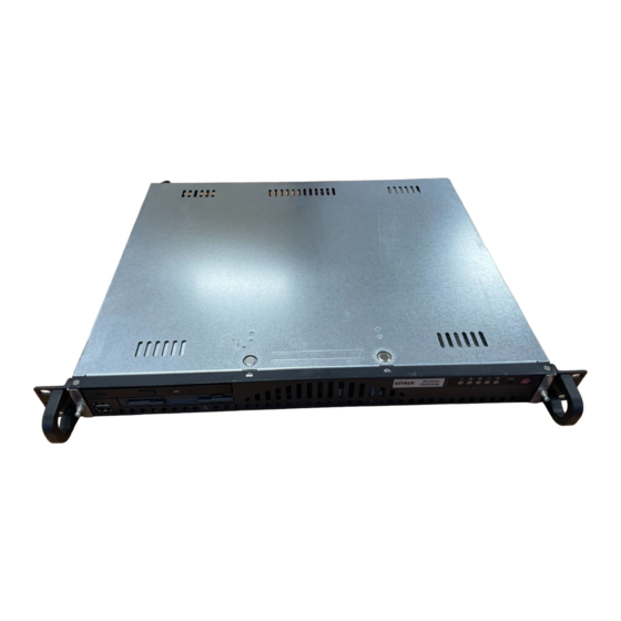
- Page 1 ® UPER 5013C-M UPER ERVER USER’S MANUAL Revision 1.0a...
- Page 2 The State of California, County of Santa Clara shall be the exclusive venue for the resolution of any such disputes. Supermicro's total liability for all claims will not exceed the price paid for the hardware product. Unless you request and receive written permission from SUPER MICRO COMPUTER, you may not copy any part of this document.
-
Page 3: About This Manual
Chapter 2: Server Installation This chapter describes the steps necessary to install the SuperServer 5013C-M into a rack and check out the server configuration prior to powering up the system. If your server was ordered without the processor and memory components, this chapter will refer you to the appropriate sections of the manual for their installation. - Page 4 UPER ERVER 5013C-M User's Manual Chapter 4: System Safety You should thoroughly familiarize yourself with this chapter for a general overview of safety precautions that should be followed when installing and servicing the SuperServer 5013C-M. Chapter 5: Advanced Motherboard Setup Chapter 5 provides detailed information on the P4SCi motherboard, including the locations and functions of connectors, headers and jumpers.
- Page 5 Preface Notes...
-
Page 6: Table Of Contents
Rack Precautions ... 2-2 Server Precautions ... 2-2 Rack Mounting Considerations ... 2-3 Installing the SuperServer 5013C-M into a Rack ... 2-4 Identifying the Sections of the Rack Rails ... 2-4 Installing the Chassis Rails ... 2-5 Installing the Rack Rails ... 2-5 Installing the Server into the Rack ... - Page 7 Chapter 4: System Safety Electrical Safety Precautions ... 4-1 General Safety Precautions ... 4-2 ESD Precautions ... 4-3 Operating Precautions ... 4-4 Chapter 5: Advanced Motherboard Setup Handling the P4SCi Motherboard ... 5-1 Motherboard Installation ... 5-2 Connecting Cables ... 5-3 Connecting Data Cables ...
- Page 8 UPER ERVER 5013C-M User's Manual SATA LED ... 5-15 5-10 Jumper Settings ... 5-16 Explanation of Jumpers ... 5-16 CMOS Clear ... 5-16 Front Side Bus Speed ... 5-16 VGA Enable/Disable ... 5-16 Watch Dog Enable/Disable ... 5-16 Speaker Jumper ... 5-16 Keyboard Wake-Up ...
- Page 9 7-4.4 PnP Configuration ... 7-9 7-4.5 Console Redirection ... 7-10 7-4.6 Hardware Monitor ... 7-11 7-4.7 Processor and Clock Options ... 7-12 Security ... 7-13 Boot ... 7-14 Exit ... 7-15 Appendices: Appendix A: BIOS POST Messages ... A-1 Appendix B: BIOS POST Codes ... B-1 Appendix C: Installing Software and Drivers ...
- Page 10 UPER ERVER 5013C-M User's Manual Notes...
-
Page 11: Chapter 1: Introduction
Overview The Supermicro SuperServer 5013C-M is a high-end single processor, mini 1U rackmount server. The 5013C-M is comprised of two main subsystems: the SC512C-260 chassis and the P4SCi motherboard. The P4SCi supports a single 478-pin Intel® Pentium® 4 microPGA processor at up to 3.40 GHz with HT (hyper-threading) technology or a single Intel Celeron®... -
Page 12: Motherboard Features
UPER ERVER 5013C-M User's Manual Motherboard Features At the heart of the SuperServer 5013C-M lies the P4SCi, a single processor motherboard designed to provide maximum performance. Below are the main features of the P4SCi. Chipset Overview The P4SCi is based on Intel’s E7210 chipset (see Figure 1-1 for a block diagram). - Page 13 The P4SCi has two 32-bit, 33 MHz (5V) PCI slots and two 64-bit, 66 MHz (3.3V) PCI-X slots. When incorporated into the 5013C-M server system, one 64-bit, 66 MHz PCI-X slot is available with the use of a riser card, which supports one full- size, half-length PCI card.
-
Page 14: Other Features
UPER ERVER 5013C-M User's Manual Other Features Other onboard features that promote system health include eight voltage moni- tors, a chassis intrusion header, auto-switching voltage regulators, chassis and CPU overheat sensors, virus protection and BIOS rescue. Figure 1-1 . Intel E7210 Chipset: Note: This is a general block diagram. -
Page 15: Server Chassis Features
Server Chassis Features The SuperServer 5013C-M is a mini 1U rackmount server platform configuration. The following is a general outline of the main features of the SC512C-260 chas- sis. System Power When configured as a SuperServer 5013C-M, the SC512C-260 chassis includes a single 260W power supply. - Page 16 UPER ERVER 5013C-M User's Manual Figure 1-2. Rear I/O Panel Parallel Port Keyboard/ Mouse Ports USB Ports COM1 Port VGA Port Ethernet Ports...
-
Page 17: Contacting Supermicro
Contacting Supermicro Headquarters Address: SuperMicro Computer, Inc. 980 Rock Ave. San Jose, CA 95131 U.S.A. Tel: +1 (408) 503-8000 Fax: +1 (408) 503-8008 Email: marketing@supermicro.com (General Information) support@supermicro.com (Technical Support) Web Site: www.supermicro.com Europe Address: SuperMicro Computer B.V. Het Sterrenbeeld 28, 5215 ML... - Page 18 UPER ERVER 5013C-M User's Manual Notes...
-
Page 19: Chapter 2: Server Installation
Decide on a suitable location for the rack unit that will hold the SuperServer 5013C-M. It should be situated in a clean, dust-free area that is well ventilated. Avoid areas where heat, electrical noise and electromagnetic fields are gener- ated. -
Page 20: Choosing A Setup Location
UPER ERVER 5013C-M User's Manual Choosing a Setup Location - Leave enough clearance in front of the rack to enable you to open the front door completely (~25 inches). - Leave approximately 30 inches of clearance in the back of the rack to allow for sufficient airflow and ease in servicing. -
Page 21: Rack Mounting Considerations
Chapter 2: Server Installation Rack Mounting Considerations Ambient Operating Temperature If installed in a closed or multi-unit rack assembly, the ambient operating temperature of the rack environment may be greater than the ambient tem- perature of the room. Therefore, consideration should be given to installing the equipment in an environment compatible with the manufacturer’s maxi- mum rated ambient temperature (Tmra). -
Page 22: Installing The Superserver 5013C-M Into A Rack
Identifying the Sections of the Rack Rails You should have received two rack rail assemblies with the SuperServer 5013C-M. Each of these assemblies consist of two sections: an inner fixed chassis rail that secures to the unit (A) and an outer fixed rack rail that secures directly to the rack itself (B). -
Page 23: Installing The Chassis Rails
Installing Chassis Rails Installing the Rack Rails Determine where you want to place the SuperServer 5013C-M in the rack (see Rack and Server Precautions in Section 2-3). Position the fixed rack rail/sliding rail guide assemblies at the desired location in the rack, keeping the sliding rail... -
Page 24: Installing The Server Into The Rack
UPER ERVER 5013C-M User's Manual using the brackets provided. Attach the other assembly to the other side of the rack, making sure that both are at the exact same height and with the rail guides facing inward. Installing the Server into the Rack You should now have rails attached to both the chassis and the rack unit. -
Page 25: Installing The Server Into A Telco Rack
Chapter 2: Server Installation Installing the Server into a Telco Rack If you are installing the SuperServer 5013C-M into a Telco type rack, follow the directions given on the previous pages for rack installation. The only difference in the installation procedure will be the positioning of the rack brackets to the rack. -
Page 26: Checking The Motherboard Setup
UPER ERVER 5013C-M User's Manual Checking the Motherboard Setup After you install the 5013C-M in the rack, you will need to open the unit to make sure the motherboard is properly installed and all the connections have been made. 1. Accessing the inside of the 5013C-M (Figure 2-5) First, release the retention screws that secure the unit to the rack. - Page 27 Chapter 2: Server Installation Figure 2-5. Accessing the Inside of the SuperServer 5013C-M...
-
Page 28: Checking The Drive Bay Setup
UPER ERVER 5013C-M User's Manual Checking the Drive Bay Setup Next, you should check to make sure the peripheral drives and the Serial ATA drive and Serial ATA backplane have been properly installed and all essen- tial connections have been made. -
Page 29: Chapter 3: System Interface
Overview There are several LEDs on the control panel and one on the Serial ATA drive carrier to keep you constantly informed of the overall status of the system as well as the activity and health of specific components. There are also two buttons on the chassis control panel. -
Page 30: Control Panel Leds
UPER ERVER 5013C-M User's Manual Control Panel LEDs The control panel located on the front of the SC512C-260 chassis has five LEDs. These LEDs provide you with critical information related to different parts of the system. This section explains what each LED indicates when illuminated and any corrective action you may need to take. -
Page 31: Power
Chapter 3: System Interface Power: Indicates power is being supplied to the system's power supply units. This LED should normally be illuminated when the system is operating. - Page 32 UPER ERVER 5013C-M User's Manual Notes...
-
Page 33: Chapter 4: System Safety
Electrical Safety Precautions Basic electrical safety precautions should be followed to protect yourself from harm and the SuperServer 5013C-M from damage: Be aware of the locations of the power on/off switch on the chassis as well as the room's emergency power-off switch, disconnection switch or electrical outlet. -
Page 34: General Safety Precautions
General Safety Precautions Follow these rules to ensure general safety: Keep the area around the SuperServer 5013C-M clean and free of clutter. The SuperServer 5013C-M weighs approximately 21 lbs (~9.5 kg) when fully loaded. When lifting the system, two people at either end should lift slowly with their feet spread out to distribute the weight. -
Page 35: Esd Precautions
ESD Precautions Electrostatic discharge (ESD) is generated by two objects with different electrical charges coming into contact with each other. An electrical discharge is created to neutralize this difference, which can damage electronic components and printed circuit boards. measures are generally sufficient to neutralize this difference before contact is made to protect your equipment from ESD: Use a grounded wrist strap designed to prevent static discharge. -
Page 36: Operating Precautions
Care must be taken to assure that the chassis cover is in place when the 5013C-M is operating to assure proper cooling. Out of warranty damage to the 5013C-M system can occur if this practice is not strictly followed. Figure 4-1. Installing the Onboard Battery... -
Page 37: Chapter 5: Advanced Motherboard Setup
Advanced Motherboard Setup This chapter covers the steps required to install the P4SCi motherboard into the SC512C chassis, connect the data and power cables and install add-on cards. All motherboard jumpers and connections are also described. A layout and quick reference chart are included in this chapter for your reference. -
Page 38: Motherboard Installation
Accessing the inside of the 5013C-M (see Figure 2-5) Two release buttons are located on the top cover of the chassis. Depressing both of these buttons while pushing the cover away from you until it stops. -
Page 39: Connecting Cables
Chapter 5: Advanced Motherboard Setup Connecting Cables Now that the motherboard is installed, the next step is to connect the cables to the board. These include the data (ribbon) cables for the peripherals and control panel and the power cables. Connecting Data Cables The ribbon cables used to transfer data from the peripheral devices have been carefully routed to prevent them from blocking the flow of cooling air... -
Page 40: I/O Ports
UPER ERVER 5013C-M User's Manual Figure 5-1. Control Panel Header Pins Power On LED Overheat LED I/O Ports The I/O ports are color coded in conformance with the PC 99 specification. See Figure 5-2 below for the colors and locations of the various I/O ports. -
Page 41: Installing Processors
Installing Processors Avoid placing direct pressure to the top of the processor package. Always remove the power cord first before add- ing, removing or changing any hardware components. Processor Support The P4SCi has a single 478-pin microPGA socket, which supports Intel Pentium 4 processors on .013 micron process or a single Intel Celeron processor of up to 2.40 GHz. - Page 42 UPER ERVER 5013C-M User's Manual Figure 5-3. 478-pin Socket: Empty and with Processor Installed Figure 5-4. Heatsink (SNK-P0002) Installation...
-
Page 43: Installing Memory
Installing Memory CAUTION! Exercise extreme care when installing or remov- ing DIMM modules to prevent any possible damage. Memory support The P4SCi supports dual-channel, ECC or non-ECC unbuffered DDR-400/333/ 266 SDRAM. Populating DIMM0A and DIMM1A and/or DIMM0B and DIMM1B with the same size/same type of memory modules will result in dual channel (two-way interleaved) operation, which is faster than single channel operation. -
Page 44: Adding Pci Cards
Adding PCI Cards 64-bit PCI-X slot The 5013C-M has a riser card (p/n CSE-RR1U-X) designed specifically for use in the SC512C 1U rackmount chassis (included with the system). This riser card allows an installed PCI-X card to sit at a 90 degree angle so it can fit inside the chassis. -
Page 45: Motherboard Details
Motherboard Details Kybd/Mouse JPWAKE Keyboard/ J P U S B Mouse J 1 1 J 1 0 COM2 W O R U S B 1 / 2 COM1 Super I/O V G A J P 3 OH FAN GLAN1 BANK0 GLAN2 BANK1 82541... -
Page 46: P4Sci Quick Reference
UPER ERVER 5013C-M User's Manual P4SCi Quick Reference Jumpers JBT1 JP1, JP2 JP20 JPL2 JPUSB JPWAKE Connectors DIMM 0A,0B,1A,1B Fans GLAN1/2 J2/J5 J3/J4 J9/J10 USB1/2 USB3/4 Description Power LED Speaker Enable VGA Enable/Disable Keylock Enable/Disable CMOS Clear CPU Clock Speed... -
Page 47: Connector Definitions
Connector Definitions Power Supply Connectors The primary power supply connector on the P4SCi meets the SSI (Superset ATX) 24-pin specifica- tion. Refer to the table on the right for the pin definitions of the ATX 24-pin power connector. must also connect the 4-pin J21 power connector to your power supply. -
Page 48: Pwr_On Connnector
UPER ERVER 5013C-M User's Manual PW_ON Connector The PW_ON connector is located on pins 1 and 2 of JF1. header should be connected to the chassis power button, which you may also configure to put the system into suspend mode (see the Power Button Mode setting in BIOS). -
Page 49: Ide Led
IDE LED The IDE LED is located on pins 13 and 14 of JF1. This LED is used to display all IDE and SATA activity. See the table on the right for pin defi- nitions. Power On LED The Power On LED connector is lo- cated on pins 15 and 16 of JF1 (use J17 for a 3-pin connector). -
Page 50: Chassis Intrusion
UPER ERVER 5013C-M User's Manual Chassis Intrusion The Chassis Intrusion header is des- ignated JL1. See the board layout for the location of JL1 and the table on the right for pin definitions. ATX PS/2 Keyboard and PS/2 Mouse Ports The ATX PS/2 keyboard and the PS/2 mouse are located on J11. -
Page 51: Wake-On-Lan
Wake-On-LAN The Wake-On-LAN header is des- ignated WOL on the motherboard. See the table on the right for pin definitions. You must enable the LAN Wake-Up setting in BIOS to use this function. (You must also have a LAN card with a Wake-On- LAN connector and cable to use this feature.) Wake-On-Ring... -
Page 52: 5-10 Jumper Settings
UPER ERVER 5013C-M User's Manual 5-10 Jumper Settings Explanation of Jumpers To modify the operation of the motherboard, jumpers can be used to choose between optional set- tings. Jumpers create shorts be- tween two pins to change the function of the connector. Pin 1 is identified with a square solder pad on the printed circuit board. -
Page 53: Vga Enable/Disable
VGA Enable/Disable J33 allows you to enable or disable the VGA port. The default position is pins 1 and 2 jumped to enable VGA. See the table on the right for jumper settings. Watch Dog Enable/Disable JP8 enables the Watch Dog function, a system monitor that takes action when a software application freezes the system. -
Page 54: Keyboard Wake-Up
UPER ERVER 5013C-M User's Manual Keyboard Wake-Up The JPWAKE jumper is used to al- low the system to be woken up by depressing a key on the keyboard from an S1 or S3 state in Win- dows OS. See the table on the right for jumper settings. -
Page 55: System Power Force On
System Power Force On Jumper JP20 allows you to enable or disable the Force-Power-On function. If enabled, system power will always stay on automatically. If disabled, the user needs to press the power button to power on the system. OH Fan Force On Jumper JP3 allows you to enable or disable the Overheat (OH) Fan Force On function. -
Page 56: 5-11 Parallel Port, Floppy And Hard Drive Connections
UPER ERVER 5013C-M User's Manual 5-11 Parallel Port, Floppy and Hard Drive Connections Use the following information to connect the floppy and hard disk drive cables. • The floppy disk drive cable has seven twisted wires. • A red mark on a wire typically designates the location of pin 1. -
Page 57: Floppy Connector
Floppy Connector The floppy connector is located on J7. See the table on the right for pin definitions. IDE Connectors There are no jumpers to config- ure the onboard IDE interfaces J2 and J5. See the table on the right for pin definitions. must use the ATA100/66 cable included with your system to benefit from the ATA100/66... - Page 58 UPER ERVER 5013C-M User's Manual Notes 5-22...
-
Page 59: Chapter 6: Advanced Chassis Setup
Advanced Chassis Setup This chapter covers the steps required to install components and perform main- tenance on the SC512C chassis. For component installation, follow the steps in the order given to eliminate the most common problems encountered. If some steps are unnecessary, skip ahead to the step that follows. Tools Required The only tool you will need to install components and perform maintainance is a Philips screwdriver. -
Page 60: Control Panel
UPER ERVER 5013C-M User's Manual Figure 6-1. Chassis Front View Figure 6-2. Keyboard/ Mouse Ports USB Ports COM1 Port Control Panel The control panel (located on the front of the chassis) must be connected to the JF1 connector on the motherboard to provide you with system control buttons and status indicators. -
Page 61: Chapter 3 For Details On The Leds And The Control Panel Buttons. Details On
JF1 can be found in Chapter 5. System Fans One 10-cm blower fan provides the cooling for the SuperServer 5013C-M. The chassis includes air seals under the blower fans and at the chassis cross sec- tion, which separates the drive bay area from the motherboard area of the chassis to promote better airflow. -
Page 62: Drive Bay Installation/Removal
CD-ROM/IDE/Floppy Disk Drives: For installing or removing the CD-ROM, IDE or floppy disk drives, you will need to gain access to the inside of the 5013C-M by removing the top cover of the chassis. Note: Only a "slim" CD-ROM drive and a "slim" floppy drive will fit in the 5013C-M. -
Page 63: Cd-Rom And Floppy Drive Installation
The top cover of the chassis must be opened to gain full access to the CD-ROM and floppy drive bays. Both the CD-ROM and the floppy drives must have a "slim" profile to fit into the 5013C-M. First, release the retention screws that secure the unit to the rack. Grasp the two handles on either side and pull the unit straight out until it locks (you will hear a "click"). -
Page 64: Power Supply
ERVER 5013C-M User's Manual Power Supply The SuperServer 5013C-M has a single 260 watt power supply. This power supply has the capability of operating at 100 or 240 input volts. Depress the main power button on the front of the chassis and then unplug the AC power cord to completely remove power from the system before removing the power supply. -
Page 65: Chapter 7: Bios
Introduction This chapter describes the AwardBIOS for the P4SCi. The Award ROM BIOS is stored in a Flash chip and can be easily upgraded using a floppy disk-based program. Note: Due to periodic changes to the BIOS, some settings may have been added or deleted and might not yet be recorded in this manual. -
Page 66: Running Setup
UPER ERVER 5013C-M User's Manual Running Setup *Optimal default settings are in bold text unless otherwise noted. The BIOS setup options described in this section are selected by choosing the appropriate text from the Main BIOS Setup screen. All displayed text is de- scribed in this section, although the screen display is often all you need to understand how to set the options (see on next page). - Page 67 Date/Time Set the system date and time. Key in the correct information in the "mm", "dd" and "yy" fields. Press the "Enter" key to save the data. Legacy Diskette A This setting allows the user to set the type of floppy disk drive installed as diskette A.
-
Page 68: 7-4 Advanced Bios Setup
UPER ERVER 5013C-M User's Manual 7-4 Advanced BIOS Setup Choose Advanced BIOS Setup from the Award BIOS main menu with the Left/ Right arrow keys. You should see the following display. Select one of the items in the left frame of the screen to go to the sub screen for that item. - Page 69 Chapter 7: BIOS Quick Boot If enabled, this feature allows the system to skip certain tests while booting. This will decrease the time needed to boot the system. The settings are "Enabled" and "Disabled". Quiet Boot This feature allows the user to activate the function of "Quiet Boot". The options are: "Enabled"...
-
Page 70: 7-4.2 Advanced Chipset Control
UPER ERVER 5013C-M User's Manual 7-4.2 Advanced Chipset Control Access the submenu to make changes to the following settings. ECC Configuration This setting allows you to enable or disable ECC (Error Correction and Checking). The options are "ECC" and "Non-ECC". -
Page 71: 7-4.3 I/O Device Configuration
Chapter 7: BIOS USB Controller This setting allows you to enable or disable the USB controller. The options are "Enabled" and "Disabled". USB 2.0 Controller This setting allows you to enable or disable the USB 2.0 (EHCI) controller. The options are "Enabled" and "Disabled". USB Legacy Support This setting allows you to enable or disable the USB and/or Keyboard/Mouse under POST and DOS. - Page 72 UPER ERVER 5013C-M User's Manual UART Mode Select This setting allows the user to select the UART mode for the BIOS. The options are "IrDA", "ASKIR" and "Normal". RxD, TxD Active This allows the user to change the settings for the "RxD, TxD Active" function.
-
Page 73: 7-4.4 Pnp Configuration
Chapter 7: BIOS Power On Function This setting allows the user to decide which method to use to power on the system. The options are "Password", "Hot Key", "Mouse Left", "Mouse Right", "Any Key" and "Button Only". KB Power On Password This setting allows the user to enter the Password when the system is powered on via keyboard. -
Page 74: 7-4.5 Console Redirection
UPER ERVER 5013C-M User's Manual Resources Controlled By This setting allows BIOS to automatically configure all boot and Plug and Play compatible devices. If you choose Auto, you cannot select the IRQ, DMA and memory base address fields because BIOS automatically assigns them. -
Page 75: 7-4.6 Hardware Monitor
Chapter 7: BIOS Agent after Boot Select "Disabled" to allows the Agent of Console Redirection to continue running after OS bootup. The Options are "Enabled" and "Disabled". 7-4.6 Hardware Monitor Choose Hardware Monitor from the Award BIOS main menu with the Left/Right arrow keys. -
Page 76: 7-4.7 Processor And Clock Options
ElectroMagnetic Interference. The options are "Enabled" and "Disabled". CPU Clock Key in a number between 100 and 233 to set the CPU clock (MHz). Supermicro does not recommend or make any guarantees with CPU overclocking. The default setting is "200 MHz". 7-12... -
Page 77: Security
Chapter 7: BIOS Security Choose Security from the Award BIOS main menu with the Left/Right arrow keys. You should see the following display: Set Supervisor Password When the item "Set Supervisor Password" is highlighted on the above screen, press the <Enter> key. When prompted, type the Supervisor Password in the dialogue box to set or to change the Supervisor Password. -
Page 78: Boot
UPER ERVER 5013C-M User's Manual Boot Choose Boot from the Award BIOS main menu with the Left/Right arrow keys. You should see the following display: Removable Device Priority This setting allows you to set the priority of removable devices. The options are "Floppy Disks", "LS120", "Zip 100", "USB-FDD0", "USB-FDD1", "USB-ZIP0"... -
Page 79: Exit
Chapter 7: BIOS Second Boot Device This item allows the user to set the second boot-up device. The options are "Removable", "Hard Disks", "CDROM", "Legacy LAN" and "Disabled". Third Boot Device This item allows the user to set the Third boot-up device. The options are "Removable", "Hard Disks", "CDROM", "Legacy LAN"... - Page 80 UPER ERVER 5013C-M User's Manual Load Fail-Safe Defaults Highlight this item and hit <Enter> to load the default settings for all items in the BIOS Setup. These are the safest settings to use. Load Optimized Defaults Highlight this item and hit <Enter> to load the optimized settings for all items in the BIOS Setup.
-
Page 81: Appendix A: Bios Post Messages
Appendix A BIOS POST Messages During the Power-On Self-Test (POST), the BIOS will check for problems. If a problem is found, the BIOS will activate an alarm or display a message. The following is a list of such BIOS messages. Beeps 1 long beep 1 long beep+2 short beeps... - Page 82 UPER ERVER 5013C-M User's Manual Notes...
-
Page 83: Appendix Bbios Post Codes
BIOS POST Codes This section lists the POST (Power On Self Testing) Codes for the Award BIOS. POST (hex) Test CMOS R/W functionality. Early chipset initialization: -Disable shadow RAM -Disable L2 cache (socket 7 or below) -Program basic chipset registers Detect memory -Auto-detection of DRAM size, type and ECC. - Page 84 UPER ERVER 5013C-M User's Manual POST (hex) Description Reserved Auto detect flash type to load appropriate flash R/W codes into the run time area in F000 for ESCD & DMI support. Reserved Use walking 1’s algorithm to check out interface in CMOS circuitry.
- Page 85 POST (hex) Description 1. Initialize multi-language 2. Put information on screen display, including Award title, CPU type, CPU speed …. Reserved Reserved Reserved Reserved Reserved Reset keyboard except Winbond 977 series Super I/O chips. Reserved Reserved Reserved Reserved Reserved Reserved Reserved Reserved Test 8254...
- Page 86 UPER ERVER 5013C-M User's Manual POST (hex) Description Reserved Initialize the combined Trend Anti-Virus code. Reserved (Optional Feature) Show message for entering AWDFLASH.EXE from FDD (optional) Reserved 1. Initialize Init_Onboard_Super_IO switch. 2. Initialize Init_Onboard_AUDIO switch. Reserved Reserved Okay to enter Setup utility; i.e. not until this POST stage can users enter the CMOS setup utility.
- Page 87 POST (hex) Description Reserved Reserved 1. Call chipset power management hook. 2. Recover the text font used by EPA logo (not for full screen logo) 3. If password is set, ask for password. Save all data in stack back to CMOS Initialize ISA PnP boot devices 1.
- Page 88 UPER ERVER 5013C-M User's Manual Notes...
-
Page 89: Appendix C: Installing Software And Drivers
6300ESB also supports two SATA host controllers, which provides support for up to two SATA ports and up to two RAID drives. The 6300ESB supports the PATA and SATA device configurations listed below. Note that the 5013C-M supports only a single SATA drive. - Page 90 UPER ERVER 5013C-M User's Manual Non-Combined Mode: Parallel ATA only, with a maximum of four devices supported. Non-Combined Mode: SATA only, with a maximum of two devices supported. Combined Mode: SATA and PATA devices, with support for two devices of each for a total of four devices maximum.
-
Page 91: C-2 Intel Hance Rapids Driver Installation
Appendix C: Installaling Software and Drivers C-2 Intel Hance Rapids Driver Installation a. Insert Supermicro's bootable CD that came with the server into the CD drive and restart the system. Upon reboot, a screen entitled "Super Micro Driver Diskette Maker" will appear. -
Page 92: C-3 Other Software Programs And Drivers
UPER ERVER 5013C-M User's Manual C-3 Other Software Programs and Drivers After you've installed Windows Operating System, the screen shown below will appear. You are now ready to install the additional software programs and drivers included on the CD. To install these software programs and drivers, click the icons to the right of these items. - Page 93 Appendix C: Installaling Software and Drivers Supero Doctor III The Supero Doctor III program is a Web base management tool that supports remote management capability. It includes Remote and Local Management tools. The local management is called SD III Client. The Supero Doctor III program included on the CDROM that came with your motherboard allows you to monitor the environment and operations of your system.
- Page 94 UPER ERVER 5013C-M User's Manual Notes...
-
Page 95: Appendix D System Specifications
Appendix D: System Specifications Appendix D System Specifications Processors Single Intel® Pentium® 4 processor of up to 3.40 GHz with hyper- threading technology at a 800/533/400 MHz front side bus speed or a single Intel Celeron® processor of up to 2.40 GHz Chipset Intel E7210 Memory Capacity... - Page 96 UPER ERVER 5013C-M User's Manual Weight Net (Bare Bone): 18 lbs. (8.2 kg.) Net (Gross): 21 lbs. (9.5 kg.) System Cooling One (1) 10-cm ball bearing blower fan System Input Requirements AC Input Voltage: 100-240 VAC Rated Input Current: 4A (115V) to 2A (230V)
Need help?
Do you have a question about the SuperServer 5013C-M and is the answer not in the manual?
Questions and answers