Table of Contents
Advertisement
Quick Links
Advertisement
Table of Contents

Related Manuals for Supero SUPERSERVER 5017R-MTF


Summary of Contents for Supero SUPERSERVER 5017R-MTF
- Page 1 UPER ® UPER ERVER 5017R-MTF 5017R-MTRF USER’S MANUAL...
- Page 2 The information in this User’s Manual has been carefully reviewed and is believed to be accurate. The vendor assumes no responsibility for any inaccuracies that may be contained in this document, makes no commitment to update or to keep current the information in this manual, or to notify any person or organization of the updates.
-
Page 3: About This Manual
Preface About This Manual This manual is written for professional system integrators and PC technicians. It provides information for the installation and use of the SuperServer 5017R-MTF/ 5017R-MTRF. Installation and maintenance should be performed by experienced technicians only. The SuperServer 5017R-MTF/5017R-MTRF is a high-end server based on the SC813MTQ-350CB/SC813MTQ-R400CB 1U rackmount chassis and the Super X9SRi-F single processor serverboard. - Page 4 UPER ERVER 5017R-MTF/5017R-MTRF User's Manual Chapter 4: System Safety You should thoroughly familiarize yourself with this chapter for a general overview of safety precautions that should be followed when installing and servicing the SuperServer 5017R-MTF/5017R-MTRF. Chapter 5: Advanced Serverboard Setup Chapter 5 provides detailed information on the X9SRi-F serverboard, including the locations and functions of connections, headers and jumpers.
- Page 5 Preface Notes...
-
Page 6: Table Of Contents
UPER ERVER 5017R-MTF/5017R-MTRF User's Manual Table of Contents Chapter 1 Introduction Overview ......................1-1 Motherboard Features ..................1-2 Processors ...................... 1-2 Memory ......................1-2 Serial ATA ......................1-2 SCU SATA ...................... 1-2 I/O Ports ......................1-2 Intel ® Intelligent Power Node Manager (NM) ..........1-3 Server Chassis Features ................ - Page 7 Table of Contents Control Panel Buttons ..................3-1 Reset ....................... 3-1 Power ......................3-1 Control Panel LEDs ..................3-2 Overheat/Fan Fail ................... 3-2 NIC2 ........................ 3-2 NIC1 ........................ 3-2 HDD ......................... 3-2 Power ......................3-3 Hard Drive Carrier LEDs ................. 3-3 Chapter 4 System Safety Electrical Safety Precautions ................
- Page 8 UPER ERVER 5017R-MTF/5017R-MTRF User's Manual Chapter 6 Advanced Chassis Setup Static-Sensitive Devices .................. 6-1 Precautions ..................... 6-1 Unpacking ....................... 6-1 Control Panel ....................6-2 Accessing the Inside of the System..............6-3 System Fans ....................6-4 Drive Bay Installation/Removal ............... 6-4 Removing the Front Bezel ................
-
Page 9: Chapter 1 Introduction
Chapter 1 Introduction Overview The SuperServer 5017R-MTF/5017R-MTRF is a high-end server comprised of two main subsystems: the SC813MTQ-350CB/SC813MTQ-R400CB 1U server chassis and the X9SRi-F single processor motherboard. Please refer to our web site for information on operating systems that have been certifi ed for use with the system (www.supermicro.com). -
Page 10: Motherboard Features
ERVER 5017R-MTF/5017R-MTRF User's Manual Motherboard Features At the heart of the SuperServer 5017R-MTF/5017R-MTRF lies the X9SRi-F, a single processor motherboard based on Intel's C600 chipset. Below are the main features of the X9SRi-F (see Figure 1-1 for a block diagram of the chipset). -
Page 11: Intel ® Intelligent Power Node Manager (Nm)
The following is a general outline of the main features of the SC813MTQ chassis. System Power When confi gured as a SuperServer 5017R-MTF, the SC813MTQ chassis includes a single 350W power supply. When confi gured as a SuperServer 5017R-MTRF, the SC813MTQ chassis includes a redundant 400W power supply. -
Page 12: System Block Diagram
UPER ERVER 5017R-MTF/5017R-MTRF User's Manual Figure 1-1. Intel C600 Chipset: System Block Diagram Note: This is a general block diagram. Please see Chapter 5 for details. #0-8 #0-4 #0-7 #0-3 VR12 #0-6 #0-2 6 PHASE #0-5 #0-1 Sandybridge-EP 8 SNB CORE... -
Page 13: Contacting Supermicro
Chapter 1: Introduction Contacting Supermicro Headquarters Address: Super Micro Computer, Inc. 980 Rock Ave. San Jose, CA 95131 U.S.A. Tel: +1 (408) 503-8000 Fax: +1 (408) 503-8008 Email: marketing@supermicro.com (General Information) support@supermicro.com (Technical Support) Web Site: www.supermicro.com Europe Address: Super Micro Computer B.V. Het Sterrenbeeld 28, 5215 ML 's-Hertogenbosch, The Netherlands Tel:... - Page 14 UPER ERVER 5017R-MTF/5017R-MTRF User's Manual Notes...
-
Page 15: Chapter 2 Server Installation
MTF/5017R-MTRF up and running. Following the steps in the order given should enable you to have the system operational within a minimal amount of time. This quick setup assumes that your 5017R-MTF/5017R-MTRF system has come to you with the processor and memory preinstalled. If your system is not already fully integrated with a motherboard, processor, system memory etc., please turn to the... -
Page 16: Rack Precautions
UPER ERVER 5017R-MTF/5017R-MTRF User's Manual installation only in a Restricted Access Location (dedicated equipment rooms, service closets and the like). • This product is not suitable for use with visual display work place devices acccording to §2 of the the German Ordinance for Work with Visual Display Units. -
Page 17: Rack Mounting Considerations
Chapter 2: Server Installation Rack Mounting Considerations Ambient Operating Temperature If installed in a closed or multi-unit rack assembly, the ambient operating tempera- ture of the rack environment may be greater than the ambient temperature of the room. Therefore, consideration should be given to installing the equipment in an environment compatible with the manufacturer’s maximum rated ambient tempera- ture (Tmra). -
Page 18: Installing The System Into A Rack
Identifying the Sections of the Rack Rails You may have received rack rail hardware with the SuperServer 5017R-MTF/5017R- MTRF. (Two front inner rails should already be attached to the chassis.) This hardware consists of two rear inner rails that secure to the chassis, one on each side just behind the preinstalled front inner rails. -
Page 19: Installing The Rack Rails
Figure 2-1. Installing Rear Inner Chassis Rails Installing the Rack Rails Determine where you want to place the SuperServer 5017R-MTF/5017R-MTRF in the rack (see Rack and Server Precautions in Section 2-3). Position the chassis rail guides at the desired location in the rack, keeping the sliding rail guide facing the inside of the rack. -
Page 20: Installing The Server Into The Rack
UPER ERVER 5017R-MTF/5017R-MTRF User's Manual Installing the Server into the Rack You should now have rails attached to both the chassis and the rack unit. The next step is to install the server into the rack. Do this by lining up the rear of the chassis rails with the front of the rack rails. -
Page 21: Installing The Server Into A Telco Rack
Chapter 2: Server Installation Installing the Server into a Telco Rack To install the SuperServer 5017R-MTF/5017R-MTRF into a Telco type rack, use two L-shaped brackets on either side of the chassis (four total). First, determine how far the server will extend out the front of the rack. Larger chassis should be positioned to balance the weight between front and back. - Page 22 UPER ERVER 5017R-MTF/5017R-MTRF User's Manual Notes...
-
Page 23: Chapter 3 System Interface
Chapter 3: System Interface Chapter 3 System Interface Overview There are several LEDs on the control panel as well as others on the hard drive carriers to keep you constantly informed of the overall status of the system as well as the activity and health of specifi... -
Page 24: Control Panel Leds
UPER ERVER 5017R-MTF/5017R-MTRF User's Manual Control Panel LEDs The control panel located on the front of the SC813MTQ chassis has fi ve LEDs. These LEDs provide you with critical information related to different parts of the system. This section explains what each LED indicates when illuminated and any corrective action you may need to take. -
Page 25: Power
Chapter 3: System Interface Power Indicates power is being supplied to the system's power supply units. This LED should normally be illuminated when the system is operating. Hard Drive Carrier LEDs Each drive carrier has two LEDs. • Green: When illuminated, the green LED on the drive carrier indicates drive activity. - Page 26 UPER ERVER 5017R-MTF/5017R-MTRF User's Manual Notes...
-
Page 27: Chapter 4 System Safety
System Safety Electrical Safety Precautions Basic electrical safety precautions should be followed to protect yourself from harm and the SuperServer 5017R-MTF/5017R-MTRF from damage: • Be aware of the locations of the power on/off switch on the chassis as well as the room's emergency power-off switch, disconnection switch or electrical outlet. -
Page 28: General Safety Precautions
General Safety Precautions Follow these rules to ensure general safety: • Keep the area around the 5017R-MTF/5017R-MTRF clean and free of clutter. • The 5017R-MTF/5017R-MTRF weighs approximately 38 lbs (~17.3 kg) when fully loaded. When lifting the system, two people at either end should lift slowly with their feet spread out to distribute the weight. -
Page 29: Esd Precautions
Chapter 4: System Safety • Remove any jewelry or metal objects from your body, which are excellent metal conductors that can create short circuits and harm you if they come into contact with printed circuit boards or areas where power is present. •... -
Page 30: Operating Precautions
UPER ERVER 5017R-MTF/5017R-MTRF User's Manual Operating Precautions Care must be taken to assure that the chassis cover is in place when the 5017R- MTF/5017R-MTRF is operating to assure proper cooling. Out of warranty damage to the system can occur if this practice is not strictly followed. -
Page 31: Chapter 5 Advanced Motherboard Setup
Chapter 5: Advanced Motherboard Setup Chapter 5 Advanced Motherboard Setup This chapter covers the steps required to install processors and heatsinks to the X9SRi-F motherboard, connect the data and power cables and install add-on cards. All motherboard jumpers and connections are described and a layout and quick reference chart are included in this chapter. -
Page 32: Processor And Heatsink Installation
UPER ERVER 5017R-MTF/5017R-MTRF User's Manual Processor and Heatsink Installation Notes: • Always connect the power cord last and always remove it before adding, re- moving or changing any hardware components. Make sure that you install the processor into the CPU socket before you install the CPU heatsink. - Page 33 Chapter 5: Advanced Motherboard Setup 3. With the lever labeled 'Close 1st' fully retracted, gently push down on the 'Open 1st' lever to open the load plate. Lift the load plate to open it completely. Gently push 4. Using your thumb and the index down to pop the load plate fi...
- Page 34 UPER ERVER 5017R-MTF/5017R-MTRF User's Manual Warning: You can only install the CPU to the socket in one direction. Make sure that the CPU is properly inserted into the socket before closing the load plate. If it doesn't close properly, do not force it as it may damage your CPU.
-
Page 35: Installing A Cpu Heatsink
Chapter 5: Advanced Motherboard Setup Installing a CPU Heatsink 1. Do not apply any thermal grease to the heatsink or the CPU die; the required amount has already been applied. 2. Place the heatsink on top of the CPU so that the four mounting holes are aligned with those on the serverboard and the heatsink bracket underneath. - Page 36 UPER ERVER 5017R-MTF/5017R-MTRF User's Manual Figure 5-1. Installing the Heatsink Figure 5-2. Removing the Heatsink Screw #4 Loosen screws in the sequence shown Screw #1 Screw #2 Motherboard Screw #3...
-
Page 37: Connecting Cables
Chapter 5: Advanced Motherboard Setup Connecting Cables Now that the processors are installed, the next step is to connect the cables to the motherboard. These include the data (ribbon) cables for the peripherals and control panel and the power cables. Connecting Data Cables The cables used to transfer data from the peripheral devices have been carefully routed in preconfi... -
Page 38: I/O Ports
UPER ERVER 5017R-MTF/5017R-MTRF User's Manual See the Connector Defi nitions section in this chapter for details and pin descrip- tions of JF1. Figure 5-1. Front Control Panel Header Pins (JF1) Ground Power LED Vcc/UID Switch HDD LED NIC1 LED NIC2 LED... -
Page 39: Installing Memory
Chapter 5: Advanced Motherboard Setup Installing Memory Note: Check the Supermicro web site for recommended memory modules. CAUTION Exercise extreme care when installing or removing DIMM modules to prevent any possible damage. Installing DIMMs 1. Insert the desired number of DIMMs into the memory slots, starting with slot DIMMA1. -
Page 40: Memory Population Guidelines
UPER ERVER 5017R-MTF/5017R-MTRF User's Manual Memory Population Guidelines DIMM slots should be populated in the following order: DIMMA1, DIMMB1, DIMMC1, DIMMD1 then DIMMA2, DIMMB2, DIMMC2, DIMMD2. • Always use DDR3 DIMM modules of the same size, type and speed. •... - Page 41 Chapter 5: Advanced Motherboard Setup Recommended Population (Balanced) DIMMA1 DIMMA2 DIMMB1 DIMMB2 DIMMC1 DIMMC2 DIMMD1 DIMMD2 Total Memory 12GB 16GB 16GB 24GB 32GB 16GB 32GB 64GB 128GB 16GB 16GB 32GB 16GB 16GB 16GB 16GB 64GB 16GB 16GB 16GB 16GB 16GB 16GB 96GB 16GB...
-
Page 42: Adding Pci Cards
UPER ERVER 5017R-MTF/5017R-MTRF User's Manual Adding PCI Cards PCI Expansion Slots One riser card is used to support a PCI expansion (add-on) card in the system. The SC813MTQ chassis can accommodate one standard size (full height full length) PCI expansion card. When viewed from the chassis front, the card installs to the left rear of the system. -
Page 43: Motherboard Details
Chapter 5: Advanced Motherboard Setup Motherboard Details Figure 5-4. SUPER X9SRi-F Layout JCOM1 JCOM1 JKBMS1 JKBMS1 JLAN1 JLAN1 JVGA JVGA UID LED UID LED JSTBY1 JSTBY1 JLAN_USB12 JLAN_USB12 JLAN2 JLAN2 UID_LED UID_SW JVGA JCOM1 FAN4 COM1 JPG1 JPG1 FAN4 FAN4 FAN4 JPL1/2: LAN 1-2 Enable... - Page 44 UPER ERVER 5017R-MTF/5017R-MTRF User's Manual Connector Description JCOM1, JCOM2 COM1 Port, COM2 Header JIPMB1 System Management Bus Header (for IPMI) JTPM1 Trusted Platform Module (TPM) Header JUSB 4/5, 6/7, 8/9 Front Accessible USB Headers JOH1 Overheat LED/Fan Fail 3-SGPIO1 Serial General Purpose I/O Headers...
-
Page 45: Connector Defi Nitions
Chapter 5: Advanced Motherboard Setup Connector Defi nitions ATX Power 24-pin Connector Pin Defi nitions (JPW1) Pin# Defi nition Pin # Defi nition Power Connectors +3.3V +3.3V The 24 - pin main power connector -12V +3.3V (JPW1) is used to provide power to the motherboard. - Page 46 UPER ERVER 5017R-MTF/5017R-MTRF User's Manual NIC1/NIC2 (LAN1/LAN2) The NIC (Network Interface Controller) LED connection for LAN port 1 is located LAN1/LAN2 LED on pins 11 and 12 of JF1, and the LED Pin Defi nitions (JF1) connection for LAN Port 2 is on Pins 9 Pin# Defi...
- Page 47 Chapter 5: Advanced Motherboard Setup Power Button The Power Button connection is located on pins 1 and 2 of JF1. Momentarily Power Button Pin Defi nitions (JF1) contacting both pins will power on/off the Pin# Defi nition system. This button can also be confi g- ured to function as a suspend button (see Signal BIOS Setup).
- Page 48 UPER ERVER 5017R-MTF/5017R-MTRF User's Manual Fan Headers The X9SRi-F has fi ve fan headers (Fan1 ~ Fan4 and FanA). These are all 4-pin fan headers, however pins 1-3 are backward Fan Header compatible with traditional 3-pin fans. Pin Defi nitions...
- Page 49 Chapter 5: Advanced Motherboard Setup Trusted Platform Module Header Trusted Platform Module Header Pin Defi nitions This header is used to connect a Trusted Pin # Defi nition Pin # Defi nition Platform Module (TPM), available sepa- LCLK rately from a third-party vendor. A TPM is LFRAME No Pin a security device that allows encryption...
- Page 50 UPER ERVER 5017R-MTF/5017R-MTRF User's Manual T-SGPIO 1/2 & 3-SGPIO 1/2 Headers Serial_Link-SGPIO Pin Defi nitions Two T-SGPIO (Serial-Link General Pur- Pin# Defi nition Defi nition pose Input/Output) headers are located next to the I-SATA ports on the mother- Ground DATA Out board.
- Page 51 Chapter 5: Advanced Motherboard Setup Overheat LED Pin Defi nitions Overheat/Fan Fail LED (JOH1 Pin# Defi nition P3V3 The JOH1 header is used to connect an OH Active LED to provide warnings of chassis over- heat. This LED will also blink to indicate OH/Fan Fail LED Pin Defi...
-
Page 52: Jumper Settings
UPER ERVER 5017R-MTF/5017R-MTRF User's Manual Jumper Settings Explanation of Jumpers To modify the operation of the mother- board, jumpers can be used to choose Connector between optional settings. Jumpers cre- Pins ate shorts between two pins to change the function of the connector. Pin 1 is Jumper identifi... - Page 53 Chapter 5: Advanced Motherboard Setup PCI Slot SMB Enable PCI Slot SMB Enable/Disable Use Jumpers JI C1/JI C2 to enable PCI-E Jumper Settings SMB (System Management Bus) support Setting Defi nition to improve system management for the Closed Enabled PCI-E slots. Default is disabled. See the Open (Default) Disabled table on the right for jumper settings.
-
Page 54: 5-10 Onboard Indicators
UPER ERVER 5017R-MTF/5017R-MTRF User's Manual 5-10 Onboard Indicators LAN1/LAN2 LEDs LAN LED The Ethernet ports (located beside the Connection Speed Indication VGA port) have two LEDs. On each Giga- LED State Defi nition bit LAN port, one LED indicates activity... -
Page 55: Sata Ports
Chapter 5: Advanced Motherboard Setup 5-11 SATA Ports SATA Port Pin Defi nitions Pin # Defi nition SATA Ports Ground Ten Serial ATA (SATA) ports (I-SATA 0~5 and S-SATA 1~4) are included on the motherboard. See the table on the Ground right for pin defi... -
Page 56: 5-12 Installing Drivers
UPER ERVER 5017R-MTF/5017R-MTRF User's Manual 5-12 Installing Drivers After all the hardware and operating system have been installed, you need to install certain drivers. The necessary drivers are all included on the Supermicro CD that came packaged with your motherboard. After inserting this CD into your CD-ROM drive, the display shown in Figure 5-4 should appear. -
Page 57: Superdoctor Iii
Chapter 5: Advanced Motherboard Setup SuperDoctor III ® The SuperDoctor III program is a Web base management tool that supports remote management capability. It includes Remote and Local Management tools. The local management is called SD III Client. The SuperDoctor III program included on the CD-ROM that came with your motherboard allows you to monitor the environment and operations of your system. - Page 58 UPER ERVER 5017R-MTF/5017R-MTRF User's Manual SuperDoctor III Interface Display Screen (Remote Control) Note: The SuperDoctor III program and User's Manual can be downloaded from the Supermicro web site at http://www.supermicro.com/products/accessories/software/ SuperDoctorIII.cfm. For Linux, we recommend using SuperDoctor II. 5-28...
-
Page 59: Chapter 6 Advanced Chassis Setup
Chapter 6: Advanced Chassis Setup Chapter 6 Advanced Chassis Setup This chapter covers the steps required to install components and perform mainte- nance on the SC813MTQ chassis. For component installation, follow the steps in the order given to eliminate the most common problems encountered. If some steps are unnecessary, skip ahead to the step that follows. -
Page 60: Control Panel
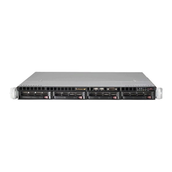
UPER ERVER 5017R-MTF/5017R-MTRF User's Manual Figure 6-1. Chassis Front View USB Ports COM2 Port Control Panel SATA Drives (4) Figure 6-2. Chassis Rear View Power Supply* PCI Expansion Slot Dedicated IPMI Port Mouse Port Keyboard Port USB Ports COM1 Port... -
Page 61: Accessing The Inside Of The System
Chapter 6: Advanced Chassis Setup Accessing the Inside of the System You will need to access the inside of the system to perform maintenance such as replacing fans and add-on cards. 1. Grasp the two handles on either side and pull the unit straight out until it locks (you will hear a "click"). -
Page 62: System Fans
UPER ERVER 5017R-MTF/5017R-MTRF User's Manual System Fans Four 4-cm high-performance fans provide the cooling for the SuperServer 5017R- MTF/5017R-MTRF. The chassis includes air seals under the fans and at the chassis cross section, which separates the drive bay area from the serverboard area of the chassis to promote better airfl... -
Page 63: Accessing The Drive Bays
Proceed to the "DVD-ROM Drive Installation" section in this chapter for instructions. Note that only a "slim" DVD-ROM drive will fi t into the 5017R-MTF/5017R-MTRF. Note: A DVD drive does not come standard with the system. -
Page 64: Sata Backplane
UPER ERVER 5017R-MTF/5017R-MTRF User's Manual Figure 6-5. Mounting a Drive in a Carrier SATA Backplane The SATA drives plug into a backplane that provides power, drive ID and bus termi- nation. A RAID controller can be used with the backplane to provide data security for the drives. - Page 65 DVD-ROM Drive Installation The top cover of the chassis must be opened to gain full access to the DVD-ROM drive bay. The 5017R-MTF/5017R-MTRF accomodates only slim DVD-ROM drives. Side mounting brackets are needed to mount a slim DVD-ROM drive into the 5017R- MTF/5017R-MTRF server.You must power down the system before installing or...
-
Page 66: Power Supply
Power Supply 5017R-MTF Power The SuperServer 5017R-MTF has a single 350 watt power supply. This power sup- ply has the capability of operating at 100 - 240 input volts. Depress the main power button on the front of the chassis and then unplug the AC power cord to completely remove power from the system before removing the power supply. -
Page 67: 5017R-Mtrf Power
Chapter 6: Advanced Chassis Setup 5017R-MTRF Power The SuperServer 5017R-MTRF has a 400 watt redundant power supply consisting of two power modules. Each power supply module has an auto-switching capability, which enables it to automatically sense and operate at a 100V - 240V input voltage. If either of the two power supply modules fail, the other module will take the full load and allow the system to continue operation without interruption. - Page 68 UPER ERVER 5017R-MTF/5017R-MTRF User's Manual Notes 6-10...
-
Page 69: Chapter 7 Bios
Chapter 7: BIOS Chapter 7 BIOS Introduction This chapter describes the AMI BIOS Setup Utility for the X9SRi/X9SRE Mother- board Series. The AMI ROM BIOS is stored in a Flash EEPROM and can be easily updated. This chapter describes the basic navigation of the AMI BIOS Setup Utility setup screens. -
Page 70: How To Start The Setup Utility
UPER ERVER 5017R-MTF/5017R-MTRF User's Manual How to Start the Setup Utility Normally, the only visible Power-On Self-Test (POST) routine is the memory test. As the memory is being tested, press the <Delete> key to enter the main menu of the AMI BIOS Setup Utility. From the main menu, you can access the other setup screens. - Page 71 Chapter 7: BIOS System Overview: The following BIOS information will be displayed: System Time/System Date Use this option to change the system time and date. Highlight System Time or Sys- tem Date using the arrow keys. Enter new values through the keyboard. Press the <Tab>...
-
Page 72: Advanced Setup Confi Gurations
UPER ERVER 5017R-MTF/5017R-MTRF User's Manual Advanced Setup Confi gurations Use the arrow keys to select Boot Setup and hit <Enter> to access the submenu items: BOOT Feature Quiet Boot This option allows the bootup screen options to be modifi ed between POST mes- sages or the OEM logo. - Page 73 Chapter 7: BIOS 19 at boot and allow the drives that are attached to these host adaptors to function as bootable disks. If this item is set to Disabled, the ROM BIOS of the host adap- tors will not capture Interrupt 19, and the drives attached to these adaptors will not function as bootable devices.
- Page 74 UPER ERVER 5017R-MTF/5017R-MTRF User's Manual Adjacent Cache Line Prefetch (Available when supported by the CPU) The CPU fetches the cache line for 64 bytes if this option is set to Disabled. The CPU fetches both cache lines for 128 bytes as comprised if Enabled.
- Page 75 Chapter 7: BIOS Power Technology This feature determines what power-saving scheme the motherboard uses. The options are Disabled, Energy Effi cient and Custom. If Custom is selected, the following options become available: EIST EIST (Enhanced Intel SpeedStep Technology) allows the system to automati- cally adjust processor voltage and core frequency in an effort to reduce power consumption and heat dissipation.
- Page 76 UPER ERVER 5017R-MTF/5017R-MTRF User's Manual DRAM RAPL - this feature enables DRAM Running Average Power Limit. The options are Disabled, Mode 0, and Mode 1. Chipset Confi guration WARNING: Setting the wrong values in the following sections may cause the system to malfunction.
- Page 77 Chapter 7: BIOS Link Speed This feature enables the user to select the target link speed for the port above. The options are GEN1, GEN2 and GEN3. IOU3 - PCIe Port This feature enables the user to select bifurcation mode for the selected root port. The options are x4x4x4x4, x4x4x8, x8x4x4, x8x8 and x16.
- Page 78 UPER ERVER 5017R-MTF/5017R-MTRF User's Manual Channel Interleaving This feature selects from the different channel memory interleaving meth- ods. The options are Auto, 1 Way, 2 Way, 3 Way and 4 Way. Rank Interleaving This feature selects from the different rank memory interleaving methods.
- Page 79 Chapter 7: BIOS South Bridge Confi guration This item displays the current South Bridge Revision. SLP_S4 Assertion Stretch Enable This feature enables or disables Assertion Stretch. The options are Enabled, and Disabled. Assertion Width This feature selects the Assertion Width. The options are 1-2 Seconds, 2-3 Seconds, 3-4 Seconds and 4-5 Seconds.
- Page 80 UPER ERVER 5017R-MTF/5017R-MTRF User's Manual IDE Mode The following items are displayed when IDE Mode is selected: Serial-ATA Controller 0~1 This feature is used to activate/deactivate the SATA controller, and sets the compatibility mode. The options are Enhanced and Compatible. The default of Serial-ATA Controller 1 is Enhanced.
- Page 81 Chapter 7: BIOS Hot Plug Set this item to Enabled to enable hot-plugging. The options are Enabled and Disabled. PCIe/PCI/PnP Confi guration This feature allows the user to set the PCI/PnP confi gurations for the following items: PCI ROM Priority In case of multiple Option ROMs (Legacy and EFI-compatible), this feature specifi...
- Page 82 UPER ERVER 5017R-MTF/5017R-MTRF User's Manual Super IO Device Confi guration Serial Port 1 / Serial Port 2 Select Enabled to enable the onboard serial port. The options are Enabled and Disabled. Serial Port1 Settings/ Serial Port2 Settings This option specifi es the base I/O port address and the Interrupt Request address of Serial Port 1 and Serial Port 2.
- Page 83 Chapter 7: BIOS Remote Access Confi guration COM1/COM2/SOL Console Redirection Use this feature to enable console redirection for COM0 and COM1 ports. The op- tions are Enabled and Disabled. The default for all ports are Disabled. Console Redirection Settings Confi...
- Page 84 UPER ERVER 5017R-MTF/5017R-MTRF User's Manual Hardware Health Confi guration Fan Speed Control Mode This feature allows the user to decide how the system controls the speeds of the onboard fans. The CPU temperature and the fan speed are correlative. When the CPU on-die temperature increases, the fan speed will also increase for effective system cooling.
- Page 85 Chapter 7: BIOS High – The processor is running hot. This is a ‘caution’ level since the CPU’s ‘Temperature Tolerance’ has been reached (or has been exceeded) and may activate an overheat alarm: The information provided above is for your reference only. For more information on thermal management, please refer to Intel’s Web site at www.Intel.com.
-
Page 86: Network Stack
UPER ERVER 5017R-MTF/5017R-MTRF User's Manual Network Stack Use this feature to enable or disable the network stach (PXE and UEFI). The op- tions are Disabled and Enabled. ME Subsystem Use this feature to disable or enable the ME (Management Engine) Subsystem. -
Page 87: Event Logs
Chapter 7: BIOS Event Logs Smbios Event Log Change this item to enable or disable all features of the Smbios Event Logging during boot. The options are Enabled and Disabled. Runtime Error Logging Support Change this item to enable or disable runtime error logging. The options are En- abled and Disabled. -
Page 88: Ipmi
UPER ERVER 5017R-MTF/5017R-MTRF User's Manual MECI The Multiple Event Count Increment (MECI) counter counts the number of oc- curences a duplicate event must happen before the MECI counter is incremented. This is a numeric value. METW The Multiple Event Time Window (METW) defi nes number of minutes must pass between duplicate log events before MECI is incremented. - Page 89 Chapter 7: BIOS BMC Self Test Log This feature logs any BMC messages returned during a BMC self-test. It shows the total number of entries and will allow the viewing of each event by scrolling down. Erase Log - Select Yes, On every reset or No. When Log is Full - Select Clear Log or Do Not Log Anymore.
-
Page 90: Iscsi
UPER ERVER 5017R-MTF/5017R-MTRF User's Manual Subnet Mask - Subnet masks tell the network which subnet this machine be- longs to. The value of each three-digit number separated by dots should not exceed 255. Station MAC Address - MAC addresses are 6 two-digit hexadecimal numbers (Base 16, 0 ~ 9, A, B, C, D, E, F) separated by dots (i.e., 00.30.48.D0.D4.60). -
Page 91: Boot Settings
Chapter 7: BIOS Boot Settings Use this feature to confi gure Boot Settings: Boot Options Priority This feature allows the user to specify which devices are boot devices and the order of priority from which the systems boots from during startup. Boot Option #1, Boot option #2, Boot Option #3, etc The settings are Built-in EFI Shell, [any detected boot device] and Disabled. -
Page 92: Security Settings
UPER ERVER 5017R-MTF/5017R-MTRF User's Manual Security Settings • If the Administrator password is defi ned ONLY - this controls access to the BIOS setup ONLY. • If the User's password is defi ned ONLY - this password will need to be entered during each system startup or boot, and will also have Administrator rights in the setup. -
Page 93: Exit Options
Chapter 7: BIOS Exit Options Select the Exit tab from the BIOS Setup Utility screen to enter the Exit BIOS Setup screen. Save Changes and Exit When you have completed the system confi guration changes, select this option to leave the BIOS Setup Utility and reboot the computer, so the new system con- fi... -
Page 94: 7-10 Main Confi Guration Page
UPER ERVER 5017R-MTF/5017R-MTRF User's Manual Save As User Defaults To set this feature, select Save as User Defaults from the Exit menu and press <En- ter>. This enables the user to save any changes to the BIOS setup for future use Restore User Defaults To set this feature, select Restore User Defaults from the Exit menu and press <En-... - Page 95 Chapter 7: BIOS Link Speed This feature changes the link speed and duplex mode for the current port. The options are AutoNeg, 10 Mbps Half, 10 Mbps Full, 100 Mbps Half and 100 Mbps Full. Wake On LAN This feature enables or disables the current port's Wake On LAN feature. When enabled, the system can be 'awaken' by sending a magic packet signal through the enabled LAN port.
- Page 96 UPER ERVER 5017R-MTF/5017R-MTRF User's Manual Notes 7-28...
-
Page 97: Appendix A Post Error Beep Codes
Appendix A: POST Error Beep Codes Appendix A POST Error Beep Codes During the POST (Power-On Self-Test) routines, which are performed each time the system is powered on, errors may occur. Non-fatal errors are those which, in most cases, allow the system to continue with bootup. - Page 98 UPER ERVER 5017R-MTF/5017R-MTRF User's Manual Notes...
-
Page 99: Appendix B Uefi Bios Recovery Instructions
Appendix B: UEFI BIOS Recovery Appendix B UEFI BIOS Recovery Instructions Warning! Do not upgrade the BIOS unless your system has a BIOS-related issue. Flashing the wrong BIOS can cause irreparable damage to the system. In no event shall Supermicro be liable for direct, indirect, special, incidental, or consequential damages arising from a BIOS update. - Page 100 UPER ERVER 5017R-MTF/5017R-MTRF User's Manual To perform UEFI BIOS recovery using a USB-attached device, follow the instruc- tions below. 1. Using a different machine, copy the "Super.ROM" binary image fi le into the disc Root "\" Directory of a USB device or a writeable CD/DVD.
- Page 101 Appendix B: UEFI BIOS Recovery Aptio Setup Utility - Copyright (C) 2011 American Megatrends, Inc. Recovery Recovery WARNING! System firmware is being updated. Keyboard is locked. DO NOT TURN THE POWER OFF!!! Once firmware update is completed press any key to reboot the system Flash update progress Select Screen Select Item...
- Page 102 UPER ERVER 5017R-MTF/5017R-MTRF User's Manual 9. After seeing the message that BIOS update is completed, unplug the AC power cable to clear CMOS, and then plug in the AC power cable to power on the system. 10. Press <Del> continuously to enter the BIOS Setup utility.
-
Page 103: Appendix C System Specifi Cations
Appendix C: System Specifi cations Appendix C System Specifi cations Processors ® ® Single Intel Xeon E5-2600/E5-1600 Series processor in an LGA 2011 socket Note: Please refer to our web site for a complete listing of supported processors. Chipset Intel C600 BIOS 8 Mb SPI AMI®... - Page 104 UPER ERVER 5017R-MTF/5017R-MTRF User's Manual Chassis SC813MTQ Form Factor: 1U rackmount Dimensions: (WxHxD) 17.2 x 1.7 x 19.85 in. (437 x 43 x 504 mm) Weight Gross Weight: 38 lbs. (17.3 kg.) System Cooling Four 4-cm high performance fans System Input Requirements AC Input Voltage: 100-240V AC auto-range Rated Input Current: 4.2A (100V) to 1.8A (240V)
- Page 105 Appendix C: System Specifi cations Regulatory Compliance Electromagnetic Emissions: FCC Class A, EN 55022 Class A, EN 61000-3-2/-3-3, CISPR 22 Class A Electromagnetic Immunity: EN 55024/CISPR 24, (EN 61000-4-2, EN 61000-4-3, EN 61000-4-4, EN 61000-4-5, EN 61000-4-6, EN 61000-4-8, EN 61000-4-11) Safety: EN 60950/IEC 60950-Compliant, UL Listed (USA), CUL Listed (Canada), TUV Certifi...
- Page 106 UPER ERVER 5017R-MTF/5017R-MTRF User's Manual Notes...
Need help?
Do you have a question about the SUPERSERVER 5017R-MTF and is the answer not in the manual?
Questions and answers