
Subscribe to Our Youtube Channel
Related Manuals for Planet Networking & Communication WGSW-24010


Summary of Contents for Planet Networking & Communication WGSW-24010
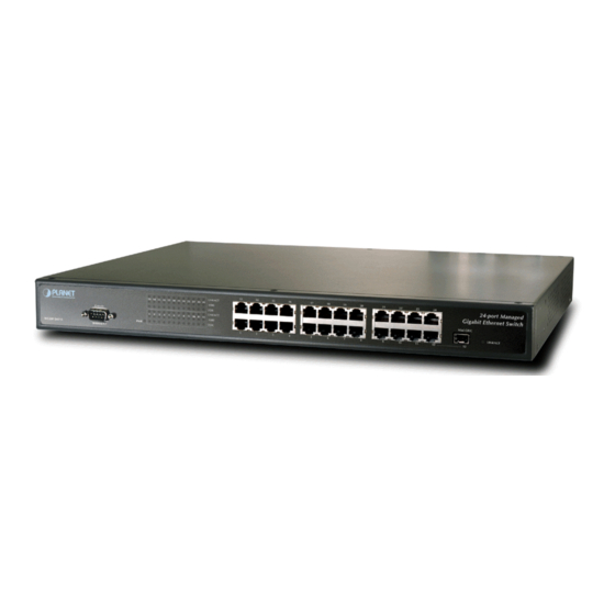
- Page 1 10/100/1000Mbps 24-port + 1 Mini-GBIC Managed Gigabit Ethernet Switch WGSW-24010 User’s Manual...
-
Page 2: Fcc Warning
PLANET has made every effort to ensure that this User ’s Manual is accurate; PLANET disclaims liability for any inaccuracies or omissions that may have occurred. -
Page 3: Table Of Contents
TABLE OF CONTENTS 1. INTRODUCTION ........................1 1.1 P ..............................1 ACKAGE ONTENTS 1.2 H ............................1 OW TO ANUAL 1.3 P ..............................1 RODUCT EATURES 1.4 P ............................2 RODUCT PECIFICATIONS 2. INSTALLATION ..........................3 2.1 P ...............................3 RODUCT ESCRIPTION 2.1.1 Product Overview...............................3 2.1.2 Switch Front Panel.............................3 2.1.3 LED Indicators ..............................3 2.1.4 Switch Rear Panel .............................3 2.2 I... - Page 4 3.5.9 sntp broadcast client enable ..........................35 3.5.10 sntp anycast client enable ..........................36 3.5.11 sntp client enable (interface)..........................36 3.5.12 sntp unicast client enable ..........................36 3.5.13 sntp unicast client poll............................37 3.5.14 sntp server ..............................37 3.5.15 show clock ..............................38 3.5.16 show sntp configuration ..........................38 3.5.17 show sntp status ............................39 3.6 C ..........................40...
- Page 5 3.10.11 ip domain-name ............................72 3.10.12 ip name-server.............................73 3.10.13 ip host ................................73 3.10.14 clear host ..............................73 3.10.15 show hosts ..............................74 3.11 LACP C ..............................75 OMMANDS 3.11.1 lacp system-priority............................75 3.11.2 lacp port-priority .............................75 3.11.3 lacp timeout ..............................75 3.11.4 show lacp ethernet............................76 3.11.5 show lacp port-channel..........................76 3.12 L ..............................77 OMMANDS...
- Page 6 3.20.1 snmp-server community ..........................111 3.20.2 snmp-server contact ............................112 3.20.3 snmp-server location ...........................112 3.20.4 snmp-server enable traps ..........................113 13.20.5 snmp-server trap authentication ........................113 3.20.6 snmp-server host ............................113 3.20.7 snmp-server set ............................114 3.20.8 show snmp..............................115 3.21 S ..........................115 PANNING OMMANDS 3.21.1 spanning-tree...............................115 3.21.2 spanning-tree mode.............................116 3.21.3 spanning-tree forward-time ..........................116 3.21.4 spanning-tree hello-time ..........................117...
- Page 7 3.26.13 show privilege ............................150 3.27 VLAN C ..............................150 OMMANDS 3.27.1 vlan database ..............................150 3.27.2 vlan ................................150 3.27.3 default-vlan disable............................151 3.27.4 interface vlan ...............................151 3.27.5 interface range vlan .............................152 3.27.6 name................................152 3.27.7 switchport mode............................153 3.27.8 switchport access vlan..........................153 3.27.9 switchport trunk allowed vlan ........................154 3.27.10 switchport trunk native vlan........................154 3.27.11 switchport general allowed vlan .........................154 3.27.12 switchport general pvid ..........................155...
- Page 8 4.3.7 Link Agreegation............................239 4.3.8 Multicast Support ............................242 4.4 S / RMON I ...........................247 TATISTICS NFORMATION 4.4.1 Table Views ..............................247 4.4.2 RMON ................................253 4.4.3 Charts ................................259 4.5 C ..........................261 ONFIGURE UALITY OF ERVICE 4.5.1 Qos Global Parameters ..........................261 5. SWITCH OPERATION ......................268 5.1 A ..............................268 DDRESS...
-
Page 9: Introduction
It contains specifications of WGSW-24010. § Appendices It contains cable information of WGSW-24010. In the following section, terms “Switch” with upper case means the two switches, i.e. WGSW-24010. Terms with lower case “switch” means any Ethernet switches. 1.3 Product Features §... -
Page 10: Product Specifications
§ 100~240VAC, 50~60Hz universal Power input § FCC, CE class A compliant 1.4 Product Specifications Model WGSW-24010 Hardware Specification 24 10/100/100 Base-T STP ports Network Ports 1 Mini-GBIC for 1000Base-SX/LX fiber-optic interface (shared with port 12) Switch Processing Scheme Store-and-Forward... -
Page 11: Installation
Basic knowledge of networking is assumed. Please read this chapter completely before continuing. 2.1 Product Description The WGSW-24010 is a powerful, high-performance 24G + 1 Mini-GBIC 10/100/1000Mbps Fast Ethernet and Gigabit managed switch with twenty-four 10/100/1000Mbps ports and 1-SFP Mini-GBIC interfaces. The SFP Mini-GBIC interfaces for fiber extension is ideal for backbone connection to other workgroup products. -
Page 12: Installing The Switch
Switch or the power adapter. 2.2 Installing the Switch This section describes how to install your WGSW-24010 Managed Gigabit Ethernet Switch and make connections to the Switch. Please read the following topics and perform the procedures in the order being presented. PLANET Managed Gigabit Ethernet Switch do not need software configuration. - Page 13 Caution: You must use the screws supplied with the mounting brackets. Damage caused to the parts by using incorrect screws would invalidate your warranty. Step3: Secure the brackets tightly. Step4: Follow the same steps to attach the second bracket to the opposite side. Step5: After the brackets are attached to the Switch, use suitable screws to securely attach the brackets to the rack, as shown in Figure 2-6 Figure 2-6 Mounting the Switch in a Rack...
-
Page 15: Console Configuration
3. CONSOLE CONFIGURATION The WGSW-24010 is a managed Ethernet Switch that can be controlled by the RS-232 console interface, telnet interface, and Web interface. This chapter describer how to configure the Switch through these interfaces. When you are ready to configure the smart functions of the Switch, make sure you had connected the supplied RS-232 serial cable to the RS-232 port at the front panel of your WGSW-24010 Switch and your PC. -
Page 16: User Exec Mode
From each mode a specific command is used to navigate from one command mode to another. The standard order to access the modes is as follows: User EXEC mode, Privileged EXEC mode, Global Configuration mode, and Interface Configuration mode. The following figure illustrates the command mode access path. When starting a session, the initial mode is the User EXEC mode. -
Page 17: Starting The Cli
To return from Global Configuration mode to Privileged EXEC mode, the user can use one of the following commands: exit § § Ctrl+Z § The following example illustrates how to access Global Configuration mode and teturn back to the Privileged EXEC mode: console # console # configure console(config) # exit... -
Page 18: Editing Features
4. When finished, exit the session with the quit or exit command. When a different user is required to log onto the system, in the Privileged EXEC Command mode the login command is entered. This effectively logs off the current user and logs on the new user. 3.2.3 Editing Features Entering Commands A CLI command is a series of keywords and arguments. -
Page 19: Command Completion
Command Completion If a command is entered and it is not complete, if the command is invalid, or if some parameters of the command are invalid or missing, the appropriate error message is displayed. This assists in entering the correct command. By pressing the <Tab>... -
Page 20: Aaa Commands
example, the command interface range port-channel has the option of either entering a range of channels, or selecting all. When the command is entered without a parameter, it automatically defaults to all. 3.3 AAA Commands 3.3.1 aaa authentication login The aaa authentication login global configuration command defines login authentication. To return to the default configuration, use the no form of this command. -
Page 21: Aaa Authentication Enable
3.3.2 aaa authentication enable The aaa authentication enable global configuration command defines authentication method lists for accessing higher privilege levels. To return to the default configuration use the no form of this command. Syntax aaa authentication enable {default | list-name} method1 [method2...] no aaa authentication enable default §... -
Page 22: Enable Authentication
no login authentication § default — Uses the default list created with the authentication login command. § list-name — Uses the indicated list created with the authentication login command. Default Configuration Uses the default set with the command authentication login. Command Mode Line Configuration mode User Guidelines... -
Page 23: Ip Https Authentication
method1 [method2...] — Specify at least one from the following table § Keyword Source or destination local Uses the local username database for authentication none Uses no authentication radius Uses the list of all RADIUS servers for authentication tacacs Uses the list of all TACACS servers for authentication Default Configuration The local user database is checked. -
Page 24: Show Authentication Methods
3.3.7 show authentication methods The authentication methods privilege EXEC command displays information about the authentication methods. Syntax show authentication methods Default Configuration This command has no default configuration. Command Mode Privileged EXEC mode User Guidelines There are no user guidelines for this command. Example The following example displays the authentication configuration. -
Page 25: Enable Password
Command Mode Line Configuration mode User Guidelines There are no user guidelines for this command. Example The following example specifies a password "abc" on a line. console (config-line) # password abc 3.3.9 enable password The enable password global configuration command sets a local password to control access to normal and privilege levels. -
Page 26: Show Users Accounts
User Guidelines Up to 30 users can be defined on the device. Example The following example configures user "bob" with the password "lee" and user level 15 to the system. console (config)# username bob password lee level 15 3.3.11 show users accounts The show users accounts privileged EXEC command displays information about the local user database. -
Page 27: Default Configuration
Default Configuration User EXEC mode commands are privilege level 1. Privileged EXEC mode and configuration mode commands are privilege level 15. The following commands are associated with privilege level 0: disable, enable, exit(EXEC), login, help. Command Modes Global configuration mode User Guidelines When the privilege level for a command is set with multiple words, note that the commands starting with the first word will also have the specified access level. -
Page 28: Show Privilege Configuration
console(config)# privilege exec 15 show interfaces console(config)# privilege exec 1 show console(config)# show privilege configuration privilege exec 15 show interfaces privilege exec 1 show The following example sets all interface ethernet and interface Port-Channel commands to level 11 except for the speed command. -
Page 29: Bridge Multicast Filtering
Syntax bridge address mac-address {ethernet interface | port-channel port-channel-number} [permanent | delete-onreset | delete-on-timeout | secure] no bridge address [mac-address] § mac-address — A valid MAC address. § Interface — A valid Ethernet port. port-channel-number — A valid port-channel number. §... -
Page 30: Bridge Multicast Address
3.4.3 bridge multicast address The bridge multicast address interface configuration command registers MAC-layer multicast addresses to the bridge table, and adds static ports to the group. To unregister the MAC address, use the no form of the bridge multicast address command. -
Page 31: Bridge Multicast Forward-Unregistered
Default Configuration No forbidden addresses are defined. Command Modes Interface Configuration (VLAN) mode User Guidelines Before defining forbidden ports, the multicast group should be registered. Examples In this example the MAC address 0100.5e02.0203 is forbidden on port g9 within VLAN 8. console (config)# interface vlan 8 console (config-if)# bridge multicast address 0100.5e02.0203 console (config-if)# bridge multicast forbidden address 0100.5e02.0203 add ethernet e9... -
Page 32: Bridge Multicast Forward-All
§ add — Forbid forwarding unregistered multicast packets. § remove — Don’t forbid forwarding unregistered multicast packets. § interface-list — Separate nonconsecutive Ethernet ports with a comma and no spaces; use a hyphen to designate a range of ports. (Range: Valid Ethernet port) §... -
Page 33: Bridge Aging-Time
Syntax bridge multicast forbidden forward-all {add | remove} {ethernet interface-list | port-channel port-channel-number-list } no bridge multicast forward-all § add — Forbids forwarding all multicast packets. § remove — Does not forbid forwarding all multicast packets. § interface-list — Separates non consecutive valid Ethernet ports with a comma and no spaces; a hyphen is used to designate a range of ports. -
Page 34: Port Security
Syntax clear bridge This command has no keywords or arguments. Default Configuration This command has no default configuration. Command Mode Privileged EXEC mode User Guidelines There are no user guidelines for this command. Example In this example, the bridge tables are cleared. console# clear bridge 3.4.11 port security The port security interface configuration command locks the port. -
Page 35: Show Bridge Address-Table
Default Configuration No addresses are defined. Command Mode Interface configuration (Ethernet, port-channel). Cannot be configured for a range of interfaces (range context). User Guidelines The command enables adding secure MAC addresses to a routed ports in port security mode. The command is available when the port is a routed port and in port security mode. -
Page 36: Show Bridge Address-Table Count
Syntax show bridge address-table static [vlan vlan] [ethernet interface | port-channel port-channel-number] § vlan — Specific valid VLAN, such as VLAN 1. § interface — A valid Ethernet port. § port-channel-number — A valid port-channel number. Default Configuration This command has no default configuration. Command Mode Privileged EXEC mode User Guidelines... -
Page 37: Show Bridge Multicast Address-Table
vlan Dynamic Static ------ -------------- --------- 3.4.16 show bridge multicast address-table The show bridge multicast address-table privileged EXEC command displays multicast MAC address table information. Syntax show bridge multicast address-table [vlan vlan-id] [address mac-multicast-address | ip-multicast-address] [format ip | mac] §... -
Page 38: Show Bridge Multicast Filtering
------ --------------- ---------- 224-239.130|2.2.3 224-239.130|2.2.8 3.4.17 show bridge multicast filtering The show bridge multicast filtering privileged EXEC command displays the multicast filtering configuration. Syntax show bridge multicast filtering vlan-id § vlan_id — A valid VLAN ID value. Default Configuration This command has no default configuration. Command Mode Privileged EXEC mode User Guidelines... -
Page 39: Clock Commands
console # show ports security Port Status Action Trap Frequency Counter ------ ---------- ---------- ------- --------------- ------------- Unlocked Discard Enable Unlocked Discard, Disable Shutdown Unlocked 3.5 Clock Commands 3.5.1 clock set The clock set privileged EXEC command manually sets the system clock. Syntax clock set hh:mm:ss day month year clock set hh:mm:ss month day year... -
Page 40: Clock Timezone
Command Mode Privileged EXEC mode User Guidelines There are no user guidelines for this command. Examples The following example configures an external time source for the system clock. console# clock source sntp 3.5.3 clock timezone The clock timezone global configuration command sets the time zone for display purposes. To set the time to Coordinated Universal Time (UTC), use the no form of this command. -
Page 41: Sntp Authentication-Key
date — Date of the month (Range:1 - 31) § § month — Month (Range: first three letters by name) § year — year - no abbreviation (Range: 2000 - 2097) § hh:mm — Time in military format, in hours and minutes (Range:hh: 0 - 23, mm:0 - 59) offset offset —... -
Page 42: Sntp Authenticate
cnsole(config)# sntp authentication-key 8 md5 ClkKey console(config)# sntp trusted-key 8 console(config)# sntp authenticate 3.5.6 sntp authenticate The sntp authenticate global configuration command grants authentication for received Network Time Protocol (NTP) traffic from servers,. To disable the feature, use the no form of this command. Syntax sntp authenticate no sntp authenticate... -
Page 43: Sntp Client Poll Timer
Console(config)# sntp authenticate 3.5.8 sntp client poll timer The sntp client poll timer global configuration command sets the polling time for the Simple Network Time Protocol (SNTP) client. To return to default, use the no form of this command. Syntax sntp client poll timer seconds no sntp client poll timer §... -
Page 44: Sntp Anycast Client Enable
3.5.10 sntp anycast client enable The sntp anycast client enable global configuration command enables anycast client. To disable the polling for SNTP broadcast client, use the no form of this command. Syntax sntp anycast client enable no sntp anycast client enable This command has no arguments or keywords. -
Page 45: Sntp Unicast Client Poll
This command has no arguments or keywords. Default Configuration Disabled Command Mode Global Configuration mode User Guidelines There are no user guidelines for this command. Examples The following example enables the device to use the Simple Network Time Protocol (SNTP) to request and accept Network Time Protocol (NTP) traffic from servers. -
Page 46: Show Clock
Default Configuration No servers are defined. Command Mode Global Configuration mode User Guidelines Up to 8 sntp servers can be defined. Use the sntp unicast client enable global configuration command to enable predefined unicast clients globally. To enable polling you should also use the sntp unicast client poll global configuration command for global enabling. Polling time is determined by the sntp client poll timer global configuration command. -
Page 47: Show Sntp Status
Examples Console# show sntp configuration Polling interval: 7200 seconds. MD5 Authentication keys: 8, 9 Authentication is required for synchronization. Trusted Keys: 8,9 Unicast Clients Polling: Enabled. Server Polling Encryption Key ----------- ----------- ---------------------- 176.1.1.8 Enabled 176.1.8.179 Disabled Disabled Broadcast Clients: Enabled Broadcast Clients Poll: Enabled Broadcast Interfaces: 1/1, 1/3 OOB SNTP servers... -
Page 48: Configuration And Image Files
Broadcast: Interface IP address Last response ------------- ----------------- ------------------------ 176.1.1.8 Primary AFE252C1.6DBDDFF2 176.1.8.179 Secondary AFE21789.643287C9 3.6 Configuration and Image Files 3.6.1 copy The copy privileged EXEC command copies files from a source to a destination. Syntax copy source-url destination-url [snmp] §... -
Page 49: Command Mode
running-config Represents the current running configuration file. startup-config Represents the startup configuration file. backup-config Represents the backup configuration file. Image The image is executable code which is decompressed during system startup, into the switching and routing software that manages the device. There are always two images stored in the device flash known as "image-1"... - Page 50 tftp cannot be the source and destination on the same copy. Copy Character Descriptions: Character Description For network transfers, an exclamation point indicates that the copy process is taking place. Each exclamation point indicates the successful transfer of ten packets (512 bytes each). For network transfers, a period indicates that the copy process timed out.
-
Page 51: Boot System
Copy took 0:0:23 [hh:mm:ss] 3.6.2 boot system The boot system privileged EXEC command specifies the system image that the device loads at startup. Syntax boot system {image-1 | image-2} § image-1 — Specifies image 1 as the system startup image. §... -
Page 52: Show Startup-Config
Console# show running-config sort feature software version 1.1 hostname device interface ethernet 1/1-2 duplex full interface ethernet 1/1-2 speed 1000 exit interface ethernet 1/1 ip address 176.242.100.100 255.255.255.0 exit interface ethernet 1/2 ip address 176.243.100.100 255.255.255.0 exit 3.6.4 show startup-config The show startup-config privileged EXEC command displays the startup configuration file contents. -
Page 53: Show Bootvar
hostname device interface ethernet 1/1-2 duplex full interface ethernet 1/1-2 speed 1000 exit interface ethernet 1/1 ip address 176.242.100.100 255.255.255.0 exit interface ethernet 1/2 ip address 176.243.100.100 255.255.255.0 exit 3.6.5 show bootvar The show bootvar privileged EXEC command displays the active system image file that the device loads at startup. Syntax show bootvar Default Configuration... -
Page 54: Interface Range Ethernet
User Guidelines There are no user guidelines for this command. Example The following example enables ports g18 for configuration. Console(config)# interface ethernet g18 Console(config-if)# 3.7.2 interface range ethernet The interface range ethernet global configuration command enters the interface configuration mode to configure multiple Ethernet type interfaces. -
Page 55: Description
The following example re-enables Ethernet port e5. Console(config)# interface ethernet e5 Console(config-if)# no shutdown 3.7.4 description The description interface configuration command adds a description to an interface. To remove the description use the no form of this command. Syntax description string no description §... -
Page 56: Duplex
3.7.6 duplex The duplex interface configuration command configures the full/half duplex operation of a given Ethernet interface when not using auto-negotiation. To restore the default, use the no form of this command. Syntax duplex {half | full} no duplex § half—Force half-duplex operation §... -
Page 57: Flowcontrol
3.7.8 flowcontrol The flowcontrol interface configuration command configures the Flow Control on a given interface. To restore the default, use the no form of this command. Syntax flowcontrol {auto | on | off | rx | tx} no flowcontrol § auto—Enables auto-negotiation of Flow Control. -
Page 58: Back-Pressure
3.7.10 back-pressure The back-pressure interface configuration command enables Back Pressure on a given interface. To disable Back Pressure, use the no form of this command. Syntax back-pressure no back-pressure Default Configuration Back Pressure is disabled. Command Mode Interface Configuration (Ethernet, port-channel) mode User Guidelines Back Pressure will operate only if duplex mode is set to half. -
Page 59: Set Interface Active
Default Configuration This command has no default configuration. Command Mode User EXEC mode User Guidelines There are no user guidelines for this command. Example In the following example, the counters for interface g1 are cleared. Console> clear counters ethernet g1 3.7.13 set interface active The set interface active privileged EXEC mode command reactivates an interface that was suspended by the system. -
Page 60: Show Interfaces Status
Console# show interfaces configuration Port Type Duplex Speed Flow Admin Back Mdix Control State Pressure Mode -------- --------- ----------- --------- --------- --------------- ------------- ---------- ----------- Full 1000 Auto Enable Auto Full Disable Full 1000 Disable Type Speed Flow Back Admin Control Pressure State... -
Page 61: Show Interfaces Description
Full Down Disable Full 1000 Disable Type Duplex Speed Flow Back Link Control Pressure State ------- -------- ----------- ----------- --------- ------------- -------------- --------- 1000 Full 1000 Disable The displayed port status information includes the following: § Port—The port number. § Description—If the port has a description, the description is displayed. -
Page 62: Show Interfaces Counters
3.7.17 show interfaces counters The show interfaces counters user EXEC command displays traffic seen by the physical interface. Syntax show interfaces counters [ethernet interface | port-channel port-channel-number] § interface — A valid Ethernet port. § port-channel-number — A valid port-channel index. Default Configuration This command has no default configuration. -
Page 63: Show Ports Jumbo-Frame
Deferred Transmissions: 0 Late Collisions: 0 Excessive Collisions: 0 Internal MAC Tx Errors: 0 Carrier Sense Errors: 0 Oversize Packets: 0 Internal MAC Rx Errors: 0 Received Pause Frames: 0 Transmitted Pause Frames: 0 The following table describes the fields shown in the display: Field Description InOctets... -
Page 64: Port Storm-Control Include-Multicast
Syntax show ports jumbo-frame Default Configuration This command has no default configuration. Command Modes User EXEC mode User Guidelines There are no user guidelines for this command. Example The following example displays the jumbo frames configuration. Console# show ports jumbo-frame Jumbo frames are disabled Jumbo frames will be enabled after reset 3.7.19 port storm-control include-multicast... -
Page 65: Port Storm-Control Broadcast Rate
User Guidelines Use the port storm-control broadcast rate interface configuration command, to set the maximum allowable broadcast rate. Multicast can be counted as part of the "storm" frames if the port storm-control include-multicast global configuration command is already executed. Example The following example enables broadcast storm control on port g5. -
Page 66: Gvrp Commands
Console# show ports storm-control Port Broadcast Storm control [kbyes/sec] ----- ------------------------------------------------- 8000 Disabled Disabled 3.8 GVRP Commands 3.8.1 gvrp enable (global) GVRP, or GARP VLAN Registration Protocol, is an industry-standard protocol designed to propagate VLAN information from device to device. With GVRP, a single switch is manually configured with all desired VLANs for the network, and all other switches on the network learn these VLANs dynamically. -
Page 67: Garp Timer
Console (config)# interface ethernet g8 Console (config-if)# gvrp enable 3.8.3 garp timer The garp timer interface configuration command adjusts the GARP application join, leave, and leaveall GARP timer values. To reset the timer to default values, use the no form of this command. Syntax garp timer {join | leave | leaveall} timer_value no garp timer... -
Page 68: Gvrp Registration-Forbid
Command Mode Interface Configuration (Ethernet, port-channel) mode User Guidelines This command forbids dynamic VLAN creation from the interface. The creation or modification of dynamic VLAN registration entries as a result of the GVRP exchanges on an interface are restricted only to those VLANs for which static VLAN registration exists. -
Page 69: Clear Gvrp Statistics
Examples The following example configures the maximum number of VLANs to 300. Console (config)# gvrp max-vlan 300 3.8.7 clear gvrp statistics The clear gvrp statistics privileged EXEC command clears all the GVRP statistics information. Syntax clear gvrp statistics [ethernet interface | port-channel port-channel-number] •... -
Page 70: Show Gvrp Statistics
Enabled Normal Enabled 10000 3.8.9 show gvrp statistics The show gvrp statistics User EXEC command displays GVRP statistics. Syntax show gvrp statistics [ethernet interface | port-channel port-channel-number] § interface — A valid Ethernet interface. § port-channel-number — A valid trunk index. Default Configuration This command has no default configuration. -
Page 71: Igmp Snooping Commands
Default Configuration This command has no default configuration. Command Mode User EXEC mode User Guidelines There are no user guidelines for this command. Example The following example displays GVRP statistics information. Console# show gvrp-error statistics GVRP error statistics: ----------------------------- Legend: INVPROT : Invalid Protocol Id INVPLEN : Invalid PDU Length INVATYP : Invalid Attribute Type... -
Page 72: Ip Igmp Snooping (Interface)
3.9.2 ip igmp snooping (Interface) The ip igmp snooping interface configuration command enables Internet Group Management Protocol (IGMP) snooping on a specific VLAN. To disable IGMP snooping on a VLAN interface, use the no form of this command. Syntax ip igmp snooping no ip igmp snooping Default Configuration IGMP snooping is disabled on all VLANs in the set context. -
Page 73: Ip Igmp Snooping Mrouter-Time-Out
Command Mode Interface Configuration (VLAN) mode User Guidelines The timeout should be at least greater than 2*query_interval+max_response_time of the IGMP router. Example The following example configures the host timeout to 300 seconds. Console (config)# interface vlan 2 Console (config-if)# ip igmp snooping host-time-out 300 3.9.5 ip igmp snooping mrouter-time-out The ip igmp snooping mrouter-time-out interface configuration command configures the mrouter-time-out. -
Page 74: Show Ip Igmp Snooping Mrouter
Use immediate leave only where there is only one host connected to a port. Example The following example configures the host leave-time-out to 60 seconds. Console (config)# interface vlan 2 Console (config-if)# ip igmp snooping leave-time-out 60 3.9.7 show ip igmp snooping mrouter The show ip igmp snooping mrouter User EXEC command displays information on dynamically learned multicast router interfaces. -
Page 75: Show Ip Igmp Snooping Groups
IGMP host timeout is 260 sec IGMP Immediate leave is disabled. IGMP leave timeout is 60 sec IGMP mrouter timeout is 300 sec Automatic learning of multicast router ports is enabled 3.9.9 show ip igmp snooping groups The show ip igmp snooping groups user EXEC command displays the multicast groups learned by IGMP snooping. Syntax show ip igmp snooping groups [vlan vlan-id] [address ip-multicast-address] vlan_id —... -
Page 76: Ip Address
Command Mode Privileged EXEC mode User Guidelines This command would delete the host name-to-address mapping temporarily until the next renew of the IP address. Examples The following example deletes all entries from the host name-to-address mapping. Console (config)# clear host dhcp * 3.10.2 ip address The ip address interface configuration command sets an IP address. -
Page 77: Ip Default-Gateway
User Guidelines The ip address dhcp command allows any interface to dynamically learn its IP address by using the DHCP protocol. Some DHCP Servers require that the DHCPDISCOVER message have a specific host name. The most typical usage of the ip address dhcp hostname host-name command is when host-name is the host name provided by the system administrator. -
Page 78: Arp
§ ethernet interface-number — Ethernet port number. § vlan vlan-id — VLAN number. § port-channel number — Port-channel number. § out-of-band-eth oob-interface — Out-of-band Ethernet port number. Default Configuration This command has no default configuration. Command Mode User EXEC mode User Guidelines There are no user guidelines for this command. -
Page 79: Clear Arp-Cache
no arp timeout seconds § seconds — Time (in seconds) that an entry remains in the ARP cache. (Range: 1 - 40000000) Default Configuration The default timeout is 60000 seconds. Command Mode Global Configuration mode User Guidelines It Is recommended not to set the timeout value to less than 3600. Note: The ARP entry is deleted between the period of the "timeout value"... -
Page 80: Ip Domain-Lookup
Up to 255 characters) Default Configuration This command has no default configuration. Command Mode Global Configuration mode User Guidelines There are no user guidelines for this command. Examples The following example defines a default domain name of www.planet.com.tw. Console (config)# ip domain-name www.planet.com.tw... -
Page 81: Ip Name-Server
3.10.12 ip name-server The ip name-server global configuration command sets the available name servers. To remove a name server, use the no form of this command. Syntax ip name-server server-address [server-address2 … server-address8] no ip name-server [server-address1 … server-address8] § server-address —... -
Page 82: Show Hosts
§ * — Removes all entries. Default Configuration This command has no default configuration. Command Mode Privileged EXEC mode User Guidelines There are no user guidelines for this command. Examples The following example deletes entries from the host name-to-address cache. Console (config)# clear host * 3.10.15 show hosts The show hosts EXEC command displays the default domain name, a list of name server hosts, the static and the cached... -
Page 83: Lacp Commands
3.11 LACP Commands 3.11.1 lacp system-priority The lacp system-priority global configuration command configures the system priority. To reset to default, use the no form of this command. Syntax lacp system-priority value no lacp system-priority § value — Value of the priority. (Range: 1 - 65535) Default Configuration The default system priority value is 1. -
Page 84: Show Lacp Ethernet
§ long — Specifies a long timeout value. § Short — Specifies a short timeout value. Default Configuration The default port timeout value is long. Command Mode Interface Configuration (Ethernet) mode User Guidelines There are no user guidelines for this command. Example The following example assigns an administrative LACP timeout for port g8 to a long timeout value. -
Page 85: Line Commands
Example The following example shows how to display LACP port-channel information. Console# show lacp port-channel 1 Port-Channel 1:Port Type 1000 Ethernet Actor System Priority:1 MAC Address: 000285:0E1C00 Admin Key: 29 Oper Key: 29 Partner System Priority:0 MAC Address: 000000:000000 Oper Key: 14 3.12 Line Commands 3.12.1 line The line global configuration command identifies a specific line for configuration and enters the line configuration... -
Page 86: Exec-Timeout
User Guidelines There are no user guidelines for this command, which is available only on the console line. Examples The following example the baud rate is set to 115200. Console (config)# line console Console(config-line)# speed 115200 3.12.3 exec-timeout The exec-timeout line configuration command sets the interval that the system waits until user input is detected. To restore the default setting, use the no form of this command. -
Page 87: Management Acl Commands
Console configuration: Interactive timeout: 20 History: 10 Baudrate: 9600 Databits: 8 Parity: none Stopbits: 1 Telnet configuration: Interactive timeout: 10 minutes 10 seconds History: 10 SSH configuration: Interactive timeout: 10 minutes 10 seconds History: 10 3.13 Management ACL Commands 3.13.1 management access-list The management access-list configuration command defines an access-list for management, and enters the access-list for configuration. -
Page 88: Permit (Management)
Console (config-macl)# permit ethernet g9 Console (config-macl)# exit Console (config)# management access-class mlist The following example shows how to create an access-list called "mlist", configure all interfaces to be management interfaces except interfaces ethernet g1 and ethernet g9, and make the access-list the active list. Console (config)# management access-list mlist Console (config-macl)# deny ethernet g1 Console (config-macl)# deny ethernet g9... -
Page 89: Management Access-Class
Syntax deny [ethernet interface-number | vlan vlan-id | port-channel number | out-of-band-eth oob-interface]] [service service] deny ip-source ip-address [mask mask | prefix-length] [ethernet interface-number | vlan vlan-id | port-channel number | out-of-band-eth oob-interface] ] [service service] § ethernet interface-number — A valid Ethernet port number. §... -
Page 90: Show Management Access-List
3.13.5 show management access-list The show management access-list privileged EXEC command displays management access-lists. Syntax show management access-list [name] § name — Name of the access list. If unspecified, defaults to an empty access-list.(Range: Valid name) Default Configuration This command has no default configuration. Command Mode Privileged EXEC mode 12.5.4 User Guidelines... -
Page 91: Phy Diagnostics Commands
3.14 PHY Diagnostics Commands 3.14.1 test copper-port tdr The test copper-port tdr privileged EXEC command diagnoses with TDR (Time Domain Reflectometry) technology the quality and characteristics of a copper cable attached to a port. Syntax test copper-port tdr interface interface — A valid Ethernet port. §... -
Page 92: Show Copper-Ports Cable-Length
Short 13:32:00 23 July 2003 Test has not been preformed Short 13:32:00 23 July 2003 Fiber 3.14.3 show copper-ports cable-length The show copper-ports cable-length privileged EXEC command displays the estimated copper cable length attached to a port. Syntax show copper-ports cable-length [interface] §... -
Page 93: Port Channel Commands
Port Temp Voltage Current Output Input Power Power Power ------ -------- ------------ ------------ ----------- ---------- --------- Copper Temp – Internally measured transceiver temperature. Voltage - Internally measured supply voltage. Current – Measured TX bias current. Output Power – Measured TX output power. Input Power –... -
Page 94: Interface Range Port-Channel
Command Mode Global Configuration mode User Guidelines Seven supported aggregated links are defined, and per port-channel, up to 4 member ports. Turning off auto-negotiation of an aggregate link may, under some circumstances, make it non-operational. If the other side has auto-negotiation turned on, it may re-synchronize all members of the aggregated link to half-duplex operation, and may, as per the standards, set them all to inactive. -
Page 95: Show Interfaces Port-Channel
User Guidelines Turning off auto-negotiation on an aggregate link may, under some circumstances make it non operational. If the other side has auto-negotiation turned on, it may re-synchronize all members of the aggregated link to half-duplex operation, and may, as per the standard, set them all to Inactive. When a port is added to a LAG, it acquires the trunk properties, as set by the administrator. -
Page 96: Show Ports Monitor
§ rx — Monitors received packets only. If no option specified, monitors both rx and tx. § tx — Monitors transmitted packets only. If no option specified, monitors both rx and tx. Default Configuration This command has no default configuration. Command Mode Interface Configuration mode User Guidelines... -
Page 97: Qos Commands
Source Port Destination Port Type Status VLAN Tagging ---------------- ----------------------- ------------ ----------- ------------------- RX, TX Active RX, TX Active 1/18 Active 3.17 QoS Commands 3.17.1 qos The qos global configuration command enables quality of service (QoS) on the device and enters QoS basic or advanced mode. -
Page 98: Wrr-Queue Cos-Map
Syntax show qos Default Configuration This command has no default configuration. Command Mode User EXEC mode User Guidelines There are no user guidelines for this command. Example The following example displays a device where basic mode is supported. Console# show qos Qos: basic Basic trust: dscp 3.17.3 wrr-queue cos-map... -
Page 99: Wrr-Queue Bandwidth
3.17.4 wrr-queue bandwidth The wrr-queue bandwidth interface configuration command assigns Weighted Round Robin (WRR) weights to egress queues. The weights ratio determines the frequency in which the packet scheduler dequeues packets from each queue. To return to the default values, use the no form of this command. Syntax wrr-queue bandwidth weight1 weight2 ... -
Page 100: Show Qos Interface
Default Configuration All queues are expedite queues. Command Mode Global Configuration mode User Guidelines When configuring the priority-queue out num-of-queues command, the weighted round robin (WRR) weight ratios are affected because there are fewer queues participating in WRR. Example The following example sets queue 7, 8 to be an EF queue. Console (config)# priority-queue out num-of-queues 2 3.17.6 show qos interface The show qos interface user EXEC command displays interface QoS data. - Page 101 Threshold qid MinDP0 MaxDP0 ProbDP0 MinDP1 MaxDP1 ProbDP1 MinDP2 MaxDP2 ProbDP2 Weight The following example displays output from the show qos interface ethernet g1 queueing command. Console# show qos interface Ethernet g1 queuing Ethernet g1 wrr bandwidth weights and EF priority: weights Priority Cos-queue map:...
-
Page 102: Qos Map Dscp-Queue
status Target Committed Target Committed Burst Rate [bps] [bytes] Enable 100000 17000 Disable Enable 200000 19000 Disable Disable Disable Enable 178000 8000 Enable 23000 1000 The following example displays output from the show qos interface g1 policers command Console# show qos interface ethernet g1 policers Ethernet g1 Class map: A Policer type: aggregate... -
Page 103: Qos Trust (Global)
User Guidelines Queue settings for 3, 11, 19, ... cannot be modified. Example The following example maps DSCP values 33, 40 and 41 to queue 1. Console (config)# qos map dscp-queue 33 40 41 to 1 3.17.8 qos trust (Global) The qos trust global configuration command can be used in basic mode to configure the system to "trust"... -
Page 104: Qos Cos
User Guidelines Use no qos trust to disable the trust mode on each port. Use qos trust to enable trust mode on each port. Example The following example configures port g5 in basic mode to default trust state (CoS). Console (config)# interface ethernet e5 Console (config-if) qos trust 3.17.10 qos cos The qos cos interface configuration command configures the default port CoS value. -
Page 105: Show Qos Map
Console(config)# qos cos override 3.17.12 show qos map The show qos map user EXEC command displays all the QoS maps. Syntax show qos map [dscp-queue | policed-dscp | dscp-mutation] dscp-queue — Displays the DSCP to queue map. § § policed-dscp — Displays the DSCP to DSCP remark table. §... -
Page 106: Radius Commands
Dscp-dscp mutation map: d1 : d2 0 ---- ------- ---- ---- ----- ---- ---- ----- ---- ---- ---- 01 02 03 04 05 06 07 08 09 11 12 13 14 15 16 17 18 19 21 22 23 24 25 26 27 28 29 31 32 33 34 35 36 37 38 39 41 42 43 44 45 46 47 48 49 51 52 53 54 55 56 57 58 59... -
Page 107: Radius-Server Key
§ Timeout period — 20 seconds Console (config)# radius-server host 192.168.10.1 auth-port 20 timeout 20 3.18.2 radius-server key The radius-server key global configuration command sets the authentication and encryption key for all RADIUS communications between the router and the RADIUS daemon. To reset to the default, use the no form of this command. Syntax radius-server key [key-string] no radius-server key... -
Page 108: Radius-Server Timeout
Syntax radius-server source-ip source no radius-server-ip § source — Specifies the source IP address. Default Configuration The default IP address is the outgoing IP interface. Command Mode Global Configuration mode User Guidelines To define an out-of-band IP address, use the out-of-band IP address format —oob/ip-address. Example The following example configures the source IP address used for communication with RADIUS servers to 10.1.1.1. -
Page 109: Show Radius-Servers
User Guidelines There are no user guidelines for this command. Example The following example sets a dead time where a RADIUS server is skipped over by transaction requests for this period, to 10 minutes. Console (config)# radius-server deadtime 10 3.18.7 show radius-servers The show radius-servers user EXEC command displays the RADIUS server settings. - Page 110 Default Configuration This command has no default configuration. Command Mode User EXEC mode User Guidelines There are no user guidelines for this command. Example The following example displays RMON Ethernet Statistics for port g1. Console# show rmon statistics ethernet g1 Port g1 Dropped: 8 Octets: 878128 Packets: 978...
-
Page 111: Rmon Collection History
octets in length inclusive (excluding framing bits but including FCS octets). 128 to 255 Octets The total number of packets (including bad packets) received that are between 128 and 255 octets in length inclusive (excluding framing bits but including FCS octets). 256 to 511 Octets The total number of packets (including bad packets) received that are between 256 and 511 octets in length inclusive (excluding framing bits but including FCS octets). -
Page 112: Show Rmon History
Example The following example displays all RMON group statistics. Console# show rmon collection history Index Interface Interval Requested Granted Owner Samples Sample ------- ---------- ----------- --------------- ------------ --------- 1000 The following table describes the significant fields shown in the display: Field Description Index... - Page 113 Console# show rmon history 5 errors Sample Set: 1 Owner: CLI Interface: 1/g1 Interval: 1800 Requested samples: 50 Granted samples: 50 Maximum table size: 500 Time CRC Align Undersize Oversize Fragments Jabbers ------------------------------ --------------- ---------------- ------------- --------------- ------------- Jan 18 2002 21:57:00 Jan 18 2002 21:57:30 The following example displays RMON Ethernet Statistics history for "other"...
-
Page 114: Rmon Alarm
during this sampling interval. This number is not necessarily the number of packets dropped, it is just the number of times this condition has been detected. Collisions The best estimate of the total number of collisions on this Ethernet segment during this sampling interval. -
Page 115: Show Rmon Alarm
Syntax show rmon alarm-table Default Configuration This command has no default configuration. Command Mode User EXEC mode User Guidelines There are no user guidelines for this command. Example The following example displays the alarms summary table. Console# show rmon alarm-table Index Owner -------... -
Page 116: Rmon Event
Falling Event: 1 Owner: CLI The following table describes the significant fields shown in the display: Field Description Monitored variable OID. Last Sample Value The statistic value during the last sampling period. For example, if the sample type is delta, this value is the difference between the samples at the beginning and end of the period. -
Page 117: Show Rmon Events
Command Mode Global Configuration mode User Guidelines There are no user guidelines for this command. Example The following example configures an event with the trap index of 10 Console (config)# rmon event 10 log 3.19.9 show rmon events The show rmon events user EXEC command displays the RMON event table. Syntax show rmon events Default Configuration... -
Page 118: Rmon Table-Size
Syntax show rmon log [event] § event — Event index. (Range: 0 - 65535) Default Configuration This command has no default configuration. Command Mode User EXEC mode User Guidelines There are no user guidelines for this command. Example The following example displays the RMON logging table. Console# show rmon log Maximum table size: 500 Event... -
Page 119: Snmp Commands
User Guidelines The configured table size is effective after the device is rebooted. Example The following example configures the maximum RMON history table sizes to 1000 entries. Console (config)# rmon table-size history 1000 3.20 SNMP Commands 3.20.1 snmp-server community The snmp-server community global configuration command sets up the community access string to permit access to the SNMP protocol. -
Page 120: Snmp-Server Contact
User Guidelines There are no user guidelines for this command. Examples The following example sets up the community access string "public" to permit administrative access to SNMP protocol, at an administrative station with the IP address 192.168.1.20. Console (config)# snmp-server community public su 192.168.1.20 The following examples set up the community access string "public"... -
Page 121: Snmp-Server Enable Traps
Console (config)# snmp-server location New_York 3.20.4 snmp-server enable traps The snmp-server enable traps global configuration command enables the switch to send SNMP traps. To disable SNMP traps use the no form of the command. Syntax snmp-server enable traps no snmp-server enable traps Default Configuration Enabled Command Mode... -
Page 122: Snmp-Server Set
§ host-address — Internet address of the host (the targeted recipient). An out-of-band IP address can be specified as described in the User Guidelines. § community-string — Password-like community string sent with the notification operation. (R ange: 1 - 20 characters) §... -
Page 123: Show Snmp
rndCommunityAccess super 3.20.8 show snmp The show snmp privileged EXEC command displays the SNMP status. Syntax show snmp Default Configuration This command has no default configuration. Command Mode Privileged EXEC mode User Guidelines There are no user guidelines for this command. Example The following example displays the SNMP communications status. -
Page 124: Spanning-Tree Mode
Syntax spanning-tree no spanning-tree Default Configuration Spanning-tree is enabled. Command Modes Global Configuration mode User Guidelines There are no user guidelines for this command. Example The following example enables spanning-tree functionality. Console(config)# spanning-tree 3.21.2 spanning-tree mode The spanning-tree mode global configuration command configures the spanning-tree protocol. To return to the default configuration, use the no form of this command. -
Page 125: Spanning-Tree Hello-Time
User Guidelines There are no user guidelines for this command. Example The following example configures spanning-tree bridge forward time to 25 seconds. Console(config)# spanning-tree forward-time 25 3.21.4 spanning-tree hello-time The spanning-tree hello-time global configuration command configures the spanning-tree bridge hello time, which is how often the switch broadcasts hello messages to other switches.To reset the default hello time, use the no form of this command. -
Page 126: Spanning-Tree Priority
3.21.6 spanning-tree priority The spanning-tree priority global configuration command configures the spanning-tree priority. The priority value is used to determine which bridge is elected as the root bridge. To reset the default spanning-tree priority use the no form of this command. -
Page 127: Spanning-Tree Port-Priority
1000 mbps (giga) — 20,000 100 mbps — 200,000 10 mbps — 2,000,000 Command Modes Interface Configuration (Ethernet, port-channel) mode User Guidelines The method used (long or short) is set by using the spanning-tree pathcost method command. Example The following example configures the spanning-tree cost on g5 to 35000. Console(config)# interface ethernet g5 Console(config-if)# spanning-tree cost 35000 3.21.9 spanning-tree port-priority... -
Page 128: Spanning-Tree Link-Type
Example The following example enables PortFast on g5 Console(config)# interface ethernet g5 Console(config-if)# spanning-tree portfast 3.21.11 spanning-tree link-type The spanning-tree link-type interface configuration command overrides the default link-type setting. To reset the default, use the no form of this command. Syntax spanning-tree link-type {point-to-point | shared} no spanning-tree spanning-tree link-type... -
Page 129: Spanning-Tree Bpdu
3.21.13 spanning-tree bpdu The spanning-tree bpdu global configuration command defines BPDU handling when spanning-tree is disabled on an interface. Syntax spanning-tree bpdu {filtering | flooding} § filtering — Filter BPDU packets when spanning-tree is disabled on an interface. § flooding — Flood BPDU packets when spanning-tree is disabled on an interface. Default Configuration The default definition is flooding. - Page 130 § instance-id — ID associated with a spanning-tree instance.(Range: 1 - 15) § detail — Display detailed information. § active — Display active ports only. § blockedports — Display blocked ports only. Default Configuration This command has no default configuration. Command Modes Privileged EXEC mode User Guidelines...
-
Page 131: Ssh And Slogin Commands
3.22 SSH and SLOGIN Commands 3.22.1 ip ssh port The ip ssh port global configuration command specifies the port to be used by the SSH server. To use the default port, use the no form of this command. Syntax ip ssh port port-number no ip ssh port §... -
Page 132: Ip Ssh Pubkey-Auth
Syntax crypto key generate dsa Default Configuration DSA key pairs do not exist. Command Mode Global Configuration mode User Guidelines DSA keys are generated in pairs: one public DSA key and one private DSA key. If the device already has DSA keys, a warning and prompt to replace the existing keys with new keys is displayed. -
Page 133: Crypto Key Pubkey-Chain Ssh
Command Mode Global Configuration mode User Guidelines AAA authentication is independent. Example The following example enables public key authentication for incoming SSH sessions. Console (config)# ip ssh pubkey-auth 3.22.6 crypto key pubkey-chain ssh The crypto key pubkey-chain ssh global configuration command enters SSH Public Key-chain configuration mode. The mode is used to manually specify other device public keys such as SSH client public keys. -
Page 134: Show Ip Ssh
3.22.8 key-string The key-string SSH public key-string configuration command manually specifies a SSH public key. Syntax key-string text § text — Authentication string that must be sentand received in the packets, using the routing protocol being authenticated. The string can contain from 1 to 16 uppercase and lowercase alphanumeric characters. Default Configuration By default, the keys do not exist. -
Page 135: Show Crypto Key Mypubkey
DSA (DSS) key was generated. SSH Public Key Authentication is enabled. Active incoming sessions: IP address Version Cipher Auth Code username ---------------- ---------------- --------------- -------------- ------------------- 172.16.0.1 John Brown 2.0 3 HMAC-SH1 The following table describes the significant fields shown in the display: Field Description IP address... -
Page 136: System Management
Default Configuration This command has no default configuration. Command Mode Privileged EXEC mode User Guidelines There are no user guidelines for this command. Examples The following example displays all SSH public keys stored on the device. Console# show crypto key pubkey-chain ssh Username Fingerprint ----------------... -
Page 137: Traceroute
64 bytes from 10.1.1.1: icmp_seq=2. time=8 ms 64 bytes from 10.1.1.1: icmp_seq=3. time=7 ms ----10.1.1.1 PING Statistics---- 4 packets transmitted, 4 packets received, 0% packet loss round-trip (ms) min/avg/max = 7/8/11 Console> The following example displays a ping to out-of-band management port 176.16.1.1. Console# ping oob/176.16.1.1 64 bytes from oob/176.16.1.1: icmp_seq=0. -
Page 138: Telnet
The traceroute command terminates when the destination responds, when the maximum TTL is exceeded, or when the user interrupts the trace with Esc. To find the trace to an out-of-band IP address, use the out-of-band IP address format: oob/ip-address. Examples console>... - Page 139 Command Mode User EXEC mode User Guidelines The Telnet software supports special Telnet commands in the form of Telnet sequences that map generic terminal control functions to operating system-specific functions. To issue a special Telnet command, enter Esc and then a command character.
-
Page 140: Resume
File Transfer Protocol ftp-data FTP data connections gopher Gopher hostname NIC hostname server ident Ident Protocol Internet Relay Chat klogin Kerberos login kshell Kerberos shell login Login Printer service nntp Network News Transport Protocol pop2 Post Office Protocol v2 pop3 Post Office Protocol v3 pim-auto-rp PIM Auto-RP... -
Page 141: Hostname
3.23.5 reload The reload privileged EXEC command reloads the operating system. Syntax reload Default Configuration This command has no default configuration. Command Mode Privileged EXEC mode User Guidelines Caution should be exercised when resetting the device, to ensure that no other activity is being performed. In particular, the user should verify that no configuration files are being downloaded at the time of reset. -
Page 142: Show Sessions
Example The following example displays information about the active users. Console# show users Username Protocol Location ---------------- ------------ ------------ Serial John 172.16.0.1 Robert HTTP 172.16.0.8 3.23.8 show sessions The show sessions command in EXEC mode lists the open Telnet sessions. Syntax show sessions This command has no arguments or keywords. - Page 143 Example The following example displays the system information. console> show system System Description: Corporate System Up Time (days,hour:min:sec): 1,22:38:21 System Contact: System Name: System location: System MAC Address: 0010.B5F4.0001 OOB MAC Address: 0010.B5F4.000F Sys Object ID: Unit Type --------- ------------------ Unit-type specific Unit-type specific Temperature Sensors:...
-
Page 144: Show Version
3.23.10 show version The show version user EXEC command displays the system version information. Syntax show version Default Configuration This command has no default configuration. Command Mode User EXEC mode User Guidelines There are no user guidelines for this command. Example The following example displays a system version (this version number is only for demonstration purposes). -
Page 145: Logging
3.24.2 logging The logging global configuration command logs messages to a syslog server. To delete the syslog server with the specified address from the list of syslogs, use the no form of this command. Syntax logging {ip-address} [port port] [severity level] [facility facility] [description text] no logging {ip-address} §... -
Page 146: Logging Buffered
3.24.4 logging buffered The logging buffered global configuration command limits syslog messages displayed from an internal buffer based on severity. To cancel the buffer use, use the no form of this command. Syntax logging buffered level no logging buffered § level —... -
Page 147: Logging File
Command Mode Privileged EXEC mode User Guidelines There are no user guidelines for this command. Example The following example clears messages from the internal syslog message logging buffer. Console# clear logging Clear logging buffer [y/n] y 3.24.7 logging file The logging file global configuration command limits syslog messages sent to the logging file based on severity. To cancel the buffer, use the no form of this command. -
Page 148: Show Logging
3.24.9 show logging The show logging privileged EXEC command displays the state of logging and the syslog messages stored in the internal buffer. Syntax show logging Default Configuration This command has no default configuration. Command Mode Privileged EXEC mode User Guidelines There are no user guidelines for this command. -
Page 149: Show Syslog-Servers
Syntax show logging file Default Configuration This command has no default configuration. Command Mode Privileged EXEC mode User Guidelines There are no user guidelines for this command. Example The following example displays the state of logging and the syslog messages stored in the logging file. Console # show logging file Logging is enabled. -
Page 150: Tacacs Commands
User Guidelines There are no user guidelines for this command. Example The following example displays the syslog server settings. Console# show syslog-servers IP address Port Severity Facility Description ---------------- ------- ------------ ------------ ---------------- 192.180.2.275 Informational local 192.180.2.285 Warning local 3.25 TACACS Commands 3.25.1 tacacs-server host The tacacs-server host command in global configuration mode specifies a TACACS+ host. -
Page 151: Tacacs-Server Key
3.25.2 tacacs-server key The tacacs-server key command in global configuration mode sets the authentication encryption key used for all TACACS+ communications between the device and the TACACS+ daemon. To disable the key, use the no form of this command. Syntax tacacs-server key key-string no tacacs-server key §... -
Page 152: Show Tacacs
Syntax tacacs-server source-ip source no tacacs-server-ip § source — Specifies the source IP address. An out-of-band IP address can be specified as described in the usage guidelines.(Range: Valid IP Address) Default Configuration The IP address would be of the outgoing IP interface. User Guidelines To define an out-of-band IP address use the out-of-band IP address format: oob/ip-address. -
Page 153: User Interface Commands
Global values -------------- TimeOut: 3 Source IP: 172.16.8.1 OOB Source IP: 176.16.8.1 3.26 User Interface Commands 3.26.1 enable The enable user EXEC command enters the privileged EXEC mode. Syntax enable [privilege-level] § privilege-level — Privilege level to enter the system. (Range: 1 - 15) Default Configuration The default privilege level is 15. -
Page 154: Configure
3.26.3 configure The configure privileged EXEC command enters the global configuration mode. Syntax configure There are no parameters for this command. Default Configuration This command has no default configuration. Command Mode Privileged EXEC mode User Guidelines There are no user guidelines for this command. Example In the following example, because no keyword is entered, a prompt is displayed. -
Page 155: Exit(Exec)
Default Configuration This command has no default configuration. Command Mode All command modes User Guidelines There are no user guidelines for this command. Example The following example changes the configuration mode from Interface Configuration mode to User EXEC mode. Console(config-if)# exit Console(config)# exit Console# 3.26.6 exit(EXEC) -
Page 156: Help
3.26.8 help The help command displays a brief description of the help system. Syntax help Default Configuration This command has no default configuration. Command Mode All Command modes User Guidelines There are no user guidelines for this command. 3.26.9 history The history line configuration command enables the command history function. -
Page 157: Debug-Mode
User Guidelines There are no user guidelines for this command. Example The following example changes the command history buffer size to 100 entries for a particular line. Console (config-line)# history size 100 3.26.11 debug-mode The debug-mode privilege EXEC command switches the mode to debug. Syntax debug-mode Default Configuration... -
Page 158: Show Privilege
3.26.13 show privilege The show privilege user EXEC command displays the current privilege level. Syntax show privilege Default Configuration This command has no default configuration. Command Mode User EXEC command mode User Guidelines There are no user guidelines for this command. Example The following example displays the current privilege level. -
Page 159: Default-Vlan Disable
vlan-range — A list of valid VLAN IDs to be added. List separate, non-consecutive VLAN IDs separated by commas § (without spaces); use a hyphen to designate a range of IDs. (Range: 2 - 4063) Default Configuration This command has no default configuration. Command Mode VLAN Database mode User Guidelines... -
Page 160: Interface Range Vlan
Example The following example configures the VLAN 1 IP address of 131.108.1.27 and subnet mask 255.255.255.0. Console (config)# interface vlan 1 Console (config-if)# ip address 131.108.1.27 255.255.255.0 3.27.5 interface range vlan The interface range vlan global configuration command enters the interface configuration mode to configure multiple VLANs. -
Page 161: Switchport Mode
3.27.7 switchport mode The switchport mode interface configuration command configures the VLAN membership mode of a port. To reset the mode to the appropriate default for the device, use the no form of this command. Syntax switchport mode {access | trunk | general} no switchport mode §... -
Page 162: Switchport Trunk Allowed Vlan
3.27.9 switchport trunk allowed vlan The switchport trunk allowed vlan interface configuration command adds or removes VLANs from a trunk port. Syntax switchport trunk allowed vlan {add vlan-list | remove vlan-list} § add vlan-list — List of VLAN IDs to add. Separate non consecutive VLAN IDs with a comma and no spaces. A hyphen designates a range of IDs. -
Page 163: Switchport General Pvid
Syntax switchport general allowed vlan add vlan-list [ tagged | untagged ] switchport general allowed vlan remove vlan-list § add vlan-list — List of VLAN IDs to add. Separate non consecutive VLAN IDs with a comma and no spaces. A hyphen designates a range of IDs. -
Page 164: Switchport General Acceptable-Frame-Type Taggedonly
no switchport general ingress-filtering disable Default Configuration Ingress filtering is enabled. Command Mode Interface Configuration (Ethernet, port-channel) mode User Guidelines There are no user guidelines for this command. Example The following example shows how to enables port ingress filtering on g8. Console (config)# interface ethernet g8 Console (config-if)# switchport general ingress-filtering disable 3.27.14 switchport general acceptable-frame-type taggedonly... -
Page 165: Map Protocol Protocols-Group
User Guidelines There are no user guidelines for this command. Example The following example forbids adding VLANs number 234 till 256, to g8. Console (config)# interface ethernet g8 Console (config-if)# switchport forbidden vlan add 234-256 3.27.16 map protocol protocols-group The map protocol protocols-group VLAN database command adds a special protocol to a named group of protocols, which may be used for protocol-based VLAN assignment. -
Page 166: Ip Internal-Usage-Vlan
User Guidelines There are no user guidelines for this command. Example The following example sets a protocol-based classification rule of protocol group 1 to VLAN 8. Console (config)# interface ethernet g8 Console (config-if)# switchport general map protocols-group 1 vlan 8 3.27.18 ip internal-usage-vlan The ip internal-usage-vlan interface configuration command reserves a VLAN as the internal usage VLAN of an interface. -
Page 167: Show Vlan Internal Usage
Console# show vlan Vlan Name Ports Type Authorization default e1-2 other Required g1-4 VLAN0010 e3-4 dynamic Required VLAN0011 e1-2 static Required VLAN0020 e3-4 static Required VLAN0021 static Required VLAN0030 static Required VLAN0031 static Not Required 3.27.20 show vlan internal usage The show vlan internal usage privileged EXEC command displays a list of VLANs being used internally by the switch. -
Page 168: Show Interfaces Switchport
Console# show vlan protocols-groups Encapsulation Protocol Group Id ------------------- ------------ ------------- ethernet 08 00 ethernet 08 06 ethernet 81 37 ethernet 81 38 rfc 1042 08 00 rfc1042 08 06 3.27.22 show interfaces switchport The show interfaces switchport privileged EXEC command displays switchport configuration. Syntax show interfaces switchport {ethernet interface | port-channel port-channel-number} §... -
Page 169: Web Server Commands
3.28 Web Server Commands 3.28.1 ip http server The ip http server global configuration command enables the device to be configured from a browser. To disable this function use the no form of this command. Syntax ip http server no ip http server Default Configuration This command has no default configuration. -
Page 170: Ip Https Server
3.28.3 ip https server The ip https server global configuration command enables the device to be configured from a secured browser. To disable this function, use the no form of this command. Syntax ip https server no ip https server Default Configuration The default for the device is disabled. -
Page 171: Show Ip Http
Command Mode Global Configuration mode User Guidelines The command is not saved in the router configuration; however, the certificate and keys generated by this command are saved in the private configuration, which is never displayed to the user or backed up to another device. Example The following example regenerates a HTTPS certificate. -
Page 172: Commands
3.29 802.1x Commands 3.29.1 aaa authentication dot1x The aaa authentication dot1x global configuration command specifies one or more authentication, authorization, and accounting (AAA) methods for use on interfaces running IEEE 802.1X. Use the no form of this command to return to default. -
Page 173: Dot1X Port-Control
3.29.3 dot1x port-control The dot1x port-control interface configuration command enables manual control of the authorization state of the port. Use the no form of this command to return to the default setting. Syntax dot1x port-control {auto | force-authorized | force-unauthorized} no dot1x port-control §... -
Page 174: Dot1X Timeout Re-Authperiod
3.29.5 dot1x timeout re-authperiod The dot1x timeout re-authperiod interface configuration command sets the number of seconds between reauthentication attempts. Use the no form of this command to return to the default setting. Syntax dot1x timeout re-authperiod seconds no dot1x timeout re-authperiod §... -
Page 175: Dot1X Timeout Tx-Period
Default Configuration Command Mode Interface configuration (Ethernet) User Guidelines During the quiet period, the switch does not accept or initiate any authentication requests. The default value of this command should only be changed to adjust for unusual circumstances, such as unreliable links or specific behavioral problems with certain clients and authentication servers. -
Page 176: Dot1X Timeout Supp-Timeout
Command Mode Interface configuration (Ethernet) mode User Guidelines There are no user guidelines for this command. Examples The following example sets the number of times that the switch sends an EAP - request/identity frame, to 6 Console (config)# interface ethernet g8 Console (config-if)# dot1x max-req 6 3.29.10 dot1x timeout supp-timeout The dot1x timeout supp-timeout interface configuration command sets the time for the retransmission of an Extensible... -
Page 177: Show Dot1X
onsole config-if(Config-VLAN)# dot1x timeout supp-timeout 3600 3.29.12 show dot1x The show dot1x privileged EXEC command displays 802.1X status for the switch or for the specified interface. Syntax show dot1x [ethernet interface] § interface —The full syntax is: unit/port. Default Configuration This command has no default configuration. -
Page 178: Show Dot1X Users
Reauth Control Reauthentication control. Reauth Period Reauthentication peiod. Username The User-Name representing the identity of the Supplicant. State The current value of the Authenticator PAE state machine. Quiet period The number of seconds that the switch remains in the quiet state following a failed authentication exchange (for example, the client provided an invalid password). -
Page 179: Show Dot1X Statistics
3.29.14 show dot1x statistics The show dot1x statistics privileged EXEC command displays 802.1X statistics for the specified interface. Syntax show dot1x statistics ethernet interface § interface — The full syntax is: unit/port. Default Configuration This command has no default configuration. Command Mode Privileged EXEC mode User Guidelines... -
Page 180: Advanced Features
LastEapolFrameVersion The protocol version number carried in the most recently received EAPOL frame. LastEapolFrameSource The source MAC address carried carried in the most recently received EAPOL frame. 3.29.15 ADVANCED FEATURES dot1x auth-not-req The dot1x auth-not-req interface VLAN configuration command enables unauthorized users access to that VLAN. Use the no form of this command to disable the access. -
Page 181: Dot1X Single-Host-Violation
3.29.18 dot1x single-host-violation The dot1x single-host-violation interface configuration command configures the action to be taken, when a station whose MAC address is not the supplicant MAC address, attempts to access the interface. Use the no form of this command to return to default. Syntax dot1x single-host-violation {forward | discard | discard-shutdown} [trap seconds] no port dot1x single-host-violation... - Page 182 console# show dot1x advanced ethernet 1/1 Guest VLAN: 3978 Unauthenticated VLANs: 91, 92 Use user attributes from Authentication Server: Enabled User VLAN not created: Create Interface Multiple Hosts Disabled Enabled Single Host Violation: Discard Trap: Enabled Frequency: 100 Status: Authorized (Locked) Counter: 9...
-
Page 183: Web Configuration
4. WEB CONFIGURATION Besides the console interface, WGSW-24010 can be configured through an Ethernet connection, make sure the manager PC must be set on same the IP subnet address with the switch. For example, if you have changed the default IP address of the Switch to 192.168.16.234 with subnet mask 255.255.255.0 via console, then the manager PC should be set at 192.168.16.x (where x is a number between 2 and 254) with subnet... -
Page 184: Configure System
Figure 3-14 main menu screen 4.2 Configure System The System section provides information for devining system parameters including security featrues, device software. Under system the folling topics are provided to devine and view the system informatin: • General • SNTP •... - Page 185 Assert The Asset page contains parameters for configuring general device information, including the system name, location, and contact, the system MAC Address, System Object ID, date, time, and System Up Time. To open Access screen perform the folling: Click System -> General -> Assert The Access information screen is displayed as in Figure 3-15.
- Page 186 Time Synchronization The Time Synchronization page contains fields for defining system time parameters for both the local hardware clock, and the external SNTP clock. If the system time is kept using an external SNTP clock, and the external SNTP clock fails, the system time reverts to the local hardware clock.
- Page 187 • New Zealand -- From the first Sunday in October until the first Sunday on or after 15th March. • Norway -- Last weekend of March until the last weekend of October. • Paraguay -- From 6th April until 7th September. •...
- Page 188 The Clock Source section contains the following fields: • The source used to set the system clock. The possible field values: Clock Source -- • Specifies that the system time is set via an SNTP server. For more information, see "SNTP Global SNTP -- Settings".
- Page 189 • Week -- The week within the month at which DST ends every year. The possible field range is 1-5. • Month -- The month of the year in which DST ends every year. The possible field range is Jan.-Dec. •...
-
Page 190: Sntp
Figure 3-18 Reset screen 4.2.2 SNTP The device supports the Simple Network Time Protocol (SNTP). SNTP assures accurate network device clock time synchronization up to the millisecond. Time synchronization is performed by a network SNTP server. SNTP operates only as a client, and cannot provide time services to other systems. The device can poll the following server types for the server time: •... -
Page 191: Sntp Global Settings
Polling for Anycast information is used when the server IP address is unknown. The first anycast server to return a response is used to set the time value. Time levels T3 and T4 are used to determine the server time. Using Anycast time information for synchronizing device time is preferred to using Broadcast time information. -
Page 192: Sntp Authentication
• Receive Anycast Servers Updates -- Polls the SNTP server for Anycast server time information, when enabled. If both the Receive Anycast Servers Update, and the Receive Broadcast Servers Update fields are enabled, the system time is set according the Anycast server time information. •... - Page 193 Click System -> SNTP -> Servers The SNTP Servers screen is displayed as in Figure 3-21. Figure 3-21 SNTP Servers screen The page includes the following fields: • SNTP Server -- Enter a user-defined SNTP server IP addresses or hostname. Up to eight SNTP servers can be defined.
-
Page 194: Logs
Figure 3-22 SNTP Broadcast Interface Table screen The page includes the following fields: • Interface -- Contains an interface list on which SNTP can be enabled. • Receive Server Updates -- The amount of time that passes before the SNTP server is polled for information. The field range is 3600 - 4294967295 seconds. - Page 195 Critical The system is in a critical state. Cannot bind to SNMP. Error A system error has occurred. Failed to delete entry. Warning A system warning has Port down. occurred. Notice The system is functioning Bad route. properly, but system notice has occurred.
-
Page 196: Log File
Figure 3-23 RAM Log Tables Log File The Log File Table contains information about log entries saved to the Log File in FLASH, including the time the log was entered, the log severity, and a description of the log message. To open Log File Table screen perform the folling: Click System ->... - Page 197 Figure 3-24 Log File Table screen The page includes the following fields: • Log Index -- The log number in the Log File Table. • Log Time -- Specifies the time at which the log was entered in the Log File Table. •...
-
Page 198: Ip Addressing
4.2.4 IP Addressing The IP Addressing page contains links for assigning interface and default gateway IP addresses, and defining ARP and DHCP parameters for the interfaces. The IP Addressing page contains links to the following topics: • Default Gateway • IP Interface Parameters •... - Page 199 To open IP Interface Parameter screen perform the folling: Click System -> IP Addressing -> IP Interface Parameter The IP Interface Parameter screen is displayed as in Figure 3-27. Figure 3-27 IP Interface Parameter screen The page includes the following fields: •...
-
Page 200: Domain Name System
Figure 3-28 DHCP IP Interface screen The page includes the following fields: • Interface -- The specific interface connected to the device. Click the option button next to Port, LAG, or VLAN and select the interface connected to the device. •... -
Page 201: Default Domain Name
Figure 3-29 Domain Name System screen The page includes the following fields: • DNS Status -- Enables or disables translating DNS names into IP addresses. • DNS Server -- Contains a list of DNS servers. DNS servers are added in the Add DNS Server page. •... -
Page 202: Host Name Mapping
Figure 3-30 Default Domain Name screen The page includes the following fields: • Default Domain Name (1-158 characters) -- Contains a user-defined DNS domain name server. When selected, the DNS domain name is the default domain. • Type -- The domain type if the domain was statically or dynamically created. •... - Page 203 Figure 3-30 Host Name Mapping screen The page includes the following fields: • Host Name -- Contains a Host Name list. Host Name are defined in the Add Host Name Mapping page. Each host provides up to eight IP addresses. The field values for the Host Name field are: •...
-
Page 204: Diagnostics
Figure 3-31 ARP Settings screen The page includes the following fields: • Global Settings -- Select this option to activate the fields for ARP global settings. • ARP Entry Age Out (1-40000000) -- For all devices, the amount of time (seconds) that passes between ARP requests about an ARP table entry. - Page 205 Integrated Cable Test The Integrated Cable Test for Copper Cables page contains fields for performing tests on copper cables. Cable testing provides information about where errors occurred in the cable, the last time a cable test was performed, and the type of cable error which occurred.
-
Page 206: Management Security
4.2.6 Management Security The Management Security page provides access tosecurity pages that contain fields for setting security parameters for ports, device management methods, user, and server security. • Access Profiles • Authentication Profiles • Select Authentication • Local User Database •... - Page 207 The page and the add pages include the following fields: • Access Profile -- User-defined Access Profile lists. The Access Profile list contains a default value of Console List, to which user-defined access profiles are added. Selecting Console Only as the Access Profile name disconnects the session, and enables accessing the device from the console only.
- Page 208 Figure 3-34 Authentication Profile screen The page includes the following fields: • Authentication Profile Name -- User-defined authentication profile lists to which user-defined authentication profiles are added. The defaults are Network Default and Console Default. • Optional Methods -- User authentication methods. Possible options are: •...
-
Page 209: Local User Database
Figure 3-35 Select Authentication screen The page includes the following fields: • Console -- Authentication profiles used to authenticate console users. • Telnet -- Authentication profiles used to authenticate Telnet users. • Secure Telnet (SSH) -- Authentication profiles used to authenticate Secure Shell (SSH) users. SSH provides clients with secure and encrypted remote connections to a device. - Page 210 Figure 3-36 Local User Database screen The page includes the following fields: • User Name -- List of users. • Access Level -- User access level. The lowest user access level is 1, and the highest user access level is 15. •...
- Page 211 Figure 3-37 Line Password screen The page includes the following fields: • Line Password for Console/Telnet/Secure Telnet (0-159 Characters) -- The line password for accessing the device via a console, Telnet, or Secure Telnet session. Passwords can contain a maximum of 159 characters. •...
- Page 212 Figure 3-38 Enable Password screen The page includes the following fields: • Select Enable Access Level -- Access level associated with the enable password. Possible field values are 1-15. • Password (0-159 Characters) -- The currently configured enable password. Enable passwords can contain a maximum of 159 characters.
- Page 213 Figure 3-39 TACACS+ Settings screen TACACS+ provides the following services: • Authentication -- Provides authentication during login and via user names and user-defined passwords. • Authorization -- Performed at login. Once the authentication session is completed, an authorization session starts using the authenticated user name. The TACACS server checks the user privileges. The TACACS+ protocol ensures network integrity through encrypted protocol exchanges between the device and TACACS+ server.
- Page 214 Default Parameters Section The TACACS+ default parameters are user-defined defaults. The default settings are applied to newly defined TACACS+ servers. If default values are not defined, the system defaults are applied to the new TACACS+ new servers. The Default Parameters section contains the following fields: •...
-
Page 215: Snmp
• Priority (1-65535) -- The server priority. The possible values are 1-65535, where 1 is the highest value. This is used to configure the order in which servers are queried. • Authentication Port -- Identifies the authentication port. The authentication port is used to verify the RADIUS server authentication. -
Page 216: Snmp Trap
The SNMP Communities screen is displayed as in Figure 3-41. Figure 3-41 SNMP Communities screen The page includes the following fields: • SNMP Management Station -- A list of management station IP addresses. • Community String -- Functions as a password and used to authenticate the selected management station to the device. -
Page 217: File Management
Figure 3-42 SNMP Trap Settings screen The page includes the following fields: • SNMP Trap -- Enables sending SNMP traps or SNMP notifications from the device to defined trap recipients. • Authentication Trap -- Enables sending SNMP traps when authentication failed to define recipients. •... - Page 218 The File Download screen is displayed as in Figure 3-43. Figure 3-43 File Download screen The page includes the following fields: • Firmware Download -- The Firmware file is downloaded. If Firmware Download is selected, the Configuration Download fields are grayed out. •...
-
Page 219: File Upload
File Upload The File Upload to Server page contains fields for uploading the software from the TFTP server to the device. The Image file can also be uploaded from the File Upload to Server page. To open File Upload screen perform the folling: Click System ->... -
Page 220: Advanced Settings
Click System -> File Management -> Copy Files The Copy Files screen is displayed as in Figure 3-45. Figure 3-45 Copy File screen The page includes the following fields: • Copy Configuration -- When selected, copies either the Running Configuration, Startup Configuration or Backup Configuration files. -
Page 221: Configure Switch
Figure 3-46 General Settings screen The page includes the following fields: • Attribute -- The general setting attribute. • Current -- The currently configured value. • After Reset -- The future (after reset) value. By entering a value in the After Reset column, memory is allocated to the field table. -
Page 222: Network Security
4.3.1 Network Security The device enables network security through both Access Control Listsand Locked Ports. The Network Security page contains links to the following topics: • Port Based Authentication • Multiple Hosts • Authenticated Users • Port Security Port Base Authentication The Port Based Authentication page contains fields for configuring port based authentication. -
Page 223: Multiple Hosts
• Admin Interface Control -- Defines the port authorization state. The possible field values are: • Authorized -- Set the interface state to authorized (permit traffic). • Unauthorized -- Set the interface state to unauthorized (deny traffic). • Auto -- Authorize state is set by the authorization method. •... - Page 224 • Port -- The port number for which Advanced Port Based Authentication is enabled. • Multiple Hosts -- Enables or disables a single host to authorize multiple hosts for system access. This setting must be enabled in order to either disable the ingress-filter, or to use port-lock security on the selected port. •...
- Page 225 • User Name -- List of users authorized via the RADIUS Server. • Port -- The port number(s) used for authentication - per user name. • Session Time -- The amount of time the user was logged on to the device. The field format is Day:Hour:Minute:Seconds, for example, 3 days: 2 hours: 4 minutes: 39 seconds.
-
Page 226: Ports
Figure 3-50 Port Security screen The page includes the following fields: • Interface -- The selected interface type on which Locked Port is enabled. • Port -- The selected interface type is a port. • LAG -- The selected interface type is a LAG. •... -
Page 227: Port Configuration
• Storm Control • Port Mirroring Port Configuration The Port Configuration page contains fields for defining port parameters. To open Port Configuration screen perform the folling: Click Switch -> Ports -> Port Configuration The Port Configuration screen is displayed as in Figure 3-51. Figure 3-51 Port Configuration screen The page includes the following fields: •... -
Page 228: Lag Configuration
• Current Duplex Mode -- The currently configured port duplex mode. • Auto Negotiation -- Enables Auto Negotiation on the port. Auto Negotiation is a protocol between two link partners that enables a port to advertise its transmission rate, duplex mode and flow control abilities to its partner. -
Page 229: Storm Control
Figure 3-52 LAG Configure screen The page includes the following fields: • LAG -- The LAG number. • Description (0-64 Characters) -- Provides a user-defined description of the configured LAG. • LAG Type -- The port types that comprise the LAG. •... -
Page 230: Port Mirroring
The Storm Control page provides fields for enabling and configuring Storm Control. To open Storm Control screen perform the folling: Click Switch -> Ports -> Strom Control The Storm Control screen is displayed as in Figure 3-53. Figure 3-53 Storm Control screen The page includes the following fields: •... - Page 231 • The port is not a VLAN member. • Only one destination port can be defined. The following restrictions apply to ports configured to be source ports: • Source Ports cannot be a LAG member. • Ports cannot be configured as a destination port. •...
-
Page 232: Address Table
4.3.3 Address Table MAC addresses are stored in either the Static Address or the Dynamic Address databases. A packet addressed to a destination stored in one of the databases is forwarded immediately to the port. The Static and Dynamic Address Tables can be sorted by interface, VLAN, and interface type. - Page 233 • Permanent -- The MAC address is permanent. • Delete on Reset -- The MAC address is deleted when the device is reset. • Delete on Timeout -- The MAC address is deleted when a timeout occurs. • Remove -- When selected, removes the the MAC address from the MAC Address Table. Dymanic Address Table The Dynamic Address Table contains fields for querying information in the dynamic address table, including the interface type, MAC addresses, VLAN, and table sorting.
-
Page 234: Garp
4.3.4 GARP Generic Attribute Registration Protocol (GARP) is a general-purpose protocol that registers any network connectivity or membership-style information. GARP defines a set of devices interested in a given network attribute, such as VLAN or Multicast address. When configuring GARP, ensure the following: •... -
Page 235: Spanning Tree
4.3.5 Spanning Tree Spanning Tree Protocol (STP) provides tree topography for any arrangement of bridges. STP also provides one path between end stations on a network, eliminating loops. Loops occur when alternate paths exist between hosts. Loops in an extended network can cause bridges to forward traffic indefinitely, resulting in increased traffic and reducing network efficiency. -
Page 236: Stp Port Settings
• Enable -- Enables Spanning Tree • Disable -- Disables Spanning Tree • STP Operation Mode -- The STP mode by which STP is enabled on the device. The possible field values are: ú Classic STP -- Enables Classic STP on the device. This is the default value. ú... - Page 237 Figure 3-59 STP Port Settings screen The page includes the following fields: • Select a Port -- Port on which STP is enabled. • STP -- Enables or disables STP on the port. • Fast Link -- When selected, enables Fast Link mode for the port. If Fast Link mode is enabled for a port, the Port State is automatically placed in the Forwarding state when the port link is up.
-
Page 238: Stp Lag Settings
ú Gigabit Ethernet - 4 • Priority (0-240, in steps of 16) -- Priority value of the port. The priority value influences the port choice when a bridge has two ports connected in a loop. The priority value is between 0-240. The priority value is provided in increments of 16. -
Page 239: Rapid Spanning Tree
ú Listening -- The LAG is in the listening mode and cannot forward traffic or learn MAC addresses. ú Learning -- The LAG is in the learning mode and cannot forward traffic, but it can learn new MAC addresses. ú Forwarding -- The LAG is currently in the forwarding mode, and it can forward traffic and learn new MAC addresses. - Page 240 Figure 3-61 Rapid Spanning Tree screen The page includes the following fields: • Interface -- Port or LAG on which Rapid STP is enabled. • Role -- The port role assigned by the STP algorithm in order to provide to STP paths. The possible field values are: ú...
-
Page 241: Vlan
4.3.6 VLAN VLANs are logical subgroups of a Local Area Network (LAN) created via software rather than defining a hardware solution. VLANs combine user stations and network devices into a single domain regardless of the physical LAN segment to which they are attached. -
Page 242: Vlan Port Settings
Figure 3-62 VLAN Membership screen The VLAN Membership page is divided into the following sections: • VLAN Membership Configuration • VLAN Port Membership Table VLAN Membership Configuration The VLAN Membership section contains parameters for assigning VLAN membership to ports. The section contains the following fields: •... -
Page 243: Vlan Lag Settings
Figure 3-63 VLAN Port Settings screen The page includes the following fields: • Port -- The port number included in the VLAN. • Port VLAN Mode -- The port mode. Possible values are: • General -- The port belongs to VLANs, and each VLAN is user-defined as tagged or untagged (full 802.1Q mode). - Page 244 Figure 3-64 VLAN LAG Settings The page includes the following fields: • LAG -- The LAG number included in the VLAN. • LAG VLAN Mode -- The LAG VLAN mode. Possible values are: • General -- The LAG belongs to VLANs, and each VLAN is user-defined as tagged or untagged (full 802.1Q mode).
- Page 245 Figure 3-64 Protocol Group screen The page includes the following fields: Frame Type -- The packet type. Possible field values are Ethernet, RFC1042, and LLC Other. Protocol Value -- User-defined protocol name. Ethernet-Based Protocol Value -- The Ethernet protocol group type. The possible field values are IP, IPX and IPV6. Protocol Group ID -- The VLAN Group ID number.
-
Page 246: Gvrp Parameters
Figure 3-65 Protocol Port Table screen The page includes the following fields: • Interface -- Port or LAG number added to a protocol group. • Group ID -- Protocol group ID to which the interface is added. Protocol group IDs are defined in the Protocol Group Table. -
Page 247: Link Agreegation
Figure 3-66 GVRP Global Parameters screen The page includes the following fields: • GVRP Global Status -- Enables or disables GVRP on the device. GVRP is disabled by default. • Interface -- The port or LAG for which GVRP is enabled. •... -
Page 248: Lacp Parameters
• The port's 802.1p priority is equal to LAGs 802.1p priority. • QoS Trust is not disabled on the port. • GVRP is not enabled. Ports can be configured as LACP ports only if the ports are not part of a previously configured LAG. Note The device uses a hash function to determine which frames are carried on which aggregated-link member. -
Page 249: Lag Membership
• Select a Port -- The port number to which timeout and priority values are assigned. • LACP Port Priority (1-65535) -- LACP priority value for the port. • LACP Timeout -- Administrative LACP timeout. The possible field values are: •... -
Page 250: Multicast Support
4.3.8 Multicast Support Multicast forwarding allows a single packet to be forwarded to multiple destinations. L2 Multicast service is based on L2 switch receiving a single packet addressed to a specific Multicast address. Multicast forwarding creates copies of the packet, and transmits the packets to the relevant ports. The device supports: •... -
Page 251: Bridge Multicast Group
Figure 3-69 Multicast Global Parameters The page includes the following fields: • Bridge Multicast Filtering -- Enables or disables bridge Multicast filtering. Disabled is the default value. IGMP Snooping can be enabled only if Bridge Multicast Filtering is enabled. • IGMP Snooping Status -- Enables or disables IGMP Snooping on the device. Disabled is the default value. Bridge Multicast Group The Bridge Multicast Group page displays the ports and LAGs attached to the Multicast service group in the Ports and LAGs tables. - Page 252 Figure 3-70 Bridge Multicast Group screen The page includes the following fields: • VLAN ID -- Identifies a VLAN and contains information about the Multicast group address. • Bridge Multicast Address -- Identifies the Multicast group MAC address/IP address. • Remove -- When selected, removes a Bridge Multicast address. •...
-
Page 253: Bridge Multicast Forward All
Toggle a port to F to forbid adding specific Multicast addresses to a specific port. Click Apply Changes. The port is assigned to the Multicast group, and the device is updated. Assigning LAGs to Receive Multicast Service Define the VLAN ID and the Bridge Multicast Address fields. Toggle the LAG to S to join the LAG to the selected Multicast group. -
Page 254: Igmp Snooping
Forbidden. Blank The port is not attached to a Multicast router or switch. Attaching a Port to a Multicast Router or Switch Define the VLAN ID field. Select a port in the Ports table, and assign the port a value. Click Apply Changes. -
Page 255: Table Views
• Host Timeout (1-2147483647) -- Time before an IGMP snooping entry is aged out. The default time is 260 seconds. • Multicast Router Timeout (1-2147483647) -- Time before aging out a Multicast router entry. The default value is 300 seconds. •... -
Page 256: Counter Summary
Figure 3-73 Utilization Summary screen The page includes the following fields: • Refresh Rate -- The amount of time that passes before the interface statistics are refreshed. • Interface -- The interface number. • Interface Status -- Status of the interface. •... -
Page 257: Interface Statistics
Figure 3-74 Counter Summary screen The page includes the following fields: • Refresh Rate -- The amount of time that passes before the interface statistics are refreshed. • Interface -- The interface number. • Interface Status -- The interface status. •... - Page 258 Figure 3-75 Interface Statistics The Interface Statistics page is divided into the following sections: • Statistics Selection • Receive Statistics • Transmit Statistics Statistics Selection The Statistics Selection section contains the following fields: • Interface -- Specifies whether statistics are displayed for a port or LAG. •...
-
Page 259: Gvrp Statistics
To open Etherlink Statistics screen perform the folling: Click Statics/RMON -> Table Views -> Etherlink Statistics The Etherlink Statistics screen is displayed as in Figure 3-76 Figure 3-76 Etherlink Statistics screen The page includes the following fields: • Interface -- Specifies whether statistics are displayed for a port or LAG. •... -
Page 260: Eap Statistics
The GVRP Statistics screen is displayed as in Figure 3-77 Figure 3-76 GVRP Statistics screen The Interface Statistics page is divided into the following sections: • Statistics Selection • GVRP Statistics Table Attribute (Counter) • GVRP Error Statistics Statistics Selection •... -
Page 261: Rmon
To open EAP Statistics screen perform the folling: Click Statics/RMON -> Table Views -> EAP Statistics The EAP Statistics screen is displayed as in Figure 3-78 Figure 3-78 EAP Statistics screen The page includes the following fields: • Port -- The port which is polled for statistics. •... -
Page 262: Rmon Statistics
• Statistics • History Control • History Table • Events Control • Events Log • Alarms RMON Statistics The RMON Statistics Group page contains fields for viewing information about device utilization and errors that occurred on the device. To open EAP Statistics screen perform the folling: Click Statics/RMON ->... - Page 263 • CRC & Align Errors -- Number of CRC and Align errors that have occurred on the interface since the device was last refreshed. • Undersize Packets -- Number of undersized packets (less than 64 octets) received on the interface since the device was last refreshed.
-
Page 264: Rmon History Table
• Remove -- When selected, removes the History Control Table entry. RMON History Table The RMON History Table contains interface specific statistical network samplings. Each table entry represents all counter values compiled during a single sample. To open RMON History Control screen perform the folling: Click Statics/RMON ->... - Page 265 • Utilization -- Estimates the main physical layer network usage on an interface during the session sampling. The value is reflected in hundredths of a percent. RMON Events Control The RMON Events Control page contains fields for defining RMON events. To open RMON History Control screen perform the folling: Click Statics/RMON ->...
-
Page 266: Rmon Alarms
The RMON Events Log screen is displayed as in Figure 3-83 Figure 3-83 RMON Event Log screen The page includes the following fields: • Event -- The RMON Events Log entry number. • Log No.-- The log number. • Log Time -- Time when the log entry was entered. •... -
Page 267: Charts
Figure 3-84 RMON Alarm screen The page includes the following fields: • Alarm Entry -- Indicates a specific alarm. • Interface -- The interface for which RMON statistics are displayed. • Counter Name -- The selected MIB variable. • Counter Value -- B class=cBold origTag="Bold" cs="Bold"> The value of the selected MIB variable. •... -
Page 268: Lag Statistics
The Chart page contains links to the following topics: • Ports • LAGs Ports The Port Statistics page contains fields for opening statistics in a chart form for port elements. To open Port Statistics screen perform the folling: Click Statics/RMON -> Charts -> Ports The Ports Statistics screen is displayed as in Figure 3-85 Figure 3-85 Port Statistics screen The page includes the following fields:... -
Page 269: Configure Quality Of Service
Figure 3-86 LAG Statistics screen The page includes the following fields: • Interface Statistics -- Selects the type of interface statistics to open. • Etherlike Statistics -- Selects the type of Etherlike statistics to open. • RMON Statistics -- Selects the type of RMON statistics to open. •... -
Page 270: Qos Settings
QoS Settings The QoS Global Settings page contains fields for enabling or disabling QoS. In addition, the Trust mode can be selected. The Trust mode relies on predefined fields within the packet to determine the output queue. To open QoS Settings screen perform the folling: Click Quality of Service ->... -
Page 271: Interface Settings
Figure 3-88 Global Queue Settings screen The page includes the following fields: • Queues -- The Queue number. • Strict Priority -- Specifies if traffic scheduling is based strictly on the queue priority. The default is enabled. • WRR -- Specifies if traffic scheduling is based on the Weighted Round Robin (WRR) weights to egress queues Interface Settings The Interface Settings page contains fields for defining, per interface, if the selected Trust mode is to be activated. - Page 272 Figure 3-89 Interface Cos/Qos Settings screen The page contains the following areas: • Interface Setting • Queue Settings Interface Settings Area The Interface Settings area includes the following fields: • Interface -- The specific port, LAG to configure: • Disable "Trust" Mode on Interface -- Disables Trust values on the device. For more information on Trust settings, see "Configuring Global CoS Settings".
-
Page 273: Dscp To Queue Mapping
Click Quality of Service -> QoS Global Parameters -> CoS to Queue The CoS to Queue Mapping Table screen is displayed as in Figure 3-90 Figure 3-90 CoS to Queue Mapping Table The page includes the following fields: • Class of Service -- Specifies the CoS priority tag values, where zero is the lowest and 7 is the highest. •... - Page 274 Figure 3-91 DSCP to Queue Mapping The page includes the following fields: • DSCP In -- The values of the DSCP field within the incoming packet. • Queue -- The queue to which packets with the specific DSCP value is assigned. The values are 1-4, where one is the lowest value and four is the highest.
-
Page 276: Switch Operation
5. SWITCH OPERATION 5.1 Address Table The Switch is implemented with an address table. This address table composed of many entries. Each entry is used to store the address information of some node in network, including MAC address, port no, etc. This information comes from the learning process of Ethernet Switch. -
Page 277: Switch
APPENDIX A A.1 Switch‘s RJ-45 Pin Assignments 1000Mbps, 1000Base T Contact MDI-X BI_DA+ BI_DB+ BI_DA- BI_DB- BI_DB+ BI_DA+ BI_DC+ BI_DD+ BI_DC- BI_DD- BI_DB- BI_DA- BI_DD+ BI_DC+ BI_DD- BI_DC- Implicit implementation of the crossover function within a twisted-pair cable, or at a wiring panel, while not expressly forbidden, is beyond the scope of this standard. -
Page 278: System Default Configuration
APPENDIX B B.1 System Default configuration. The following file is the factory default settings of WGSW-24010. Once you have to reset your WGSW-24010 configuration to default values, please upload the file to replace the running/startup/backup configuration. no spanning-tree interface range ethernet all...
Need help?
Do you have a question about the WGSW-24010 and is the answer not in the manual?
Questions and answers