Table of Contents
Advertisement
Quick Links
Download this manual
See also:
User Manual
Advertisement
Table of Contents

Subscribe to Our Youtube Channel
Related Manuals for Planet Networking & Communication WGSW-24010


Summary of Contents for Planet Networking & Communication WGSW-24010
- Page 1 10/100/1000Mbps 24-port + 1 Mini-GBIC Managed Gigabit Ethernet Switch WGSW-24010 User’s Manual...
-
Page 2: Fcc Warning
This is a Class A product. In a domestic environment, this product may cause radio interference, in which case the user may be required to take adequate measures. Revision PLANET Gigabit Ethernet Switch User's Manual FOR MODELS: WGSW-24010 Part No.: EM_WGSW24010... - Page 3 TABLE OF CONTENTS 1. INTRODUCTION ........................1 1.1 P ..............................1 ACKAGE ONTENTS 1.2 H ............................1 OW TO ANUAL 1.3 P ..............................1 RODUCT EATURES 1.4 P ............................2 RODUCT PECIFICATIONS 2. INSTALLATION ..........................3 2.1 P ...............................3 RODUCT ESCRIPTION 2.1.1 Product Overview...............................3 2.1.2 Switch Front Panel.............................3 2.1.3 LED Indicators ..............................3 2.1.4 Switch Rear Panel .............................3 2.2 I...
- Page 4 SNMP Trap ...................................45 4.2.8 File Management .............................46 File Download ..................................46 File Upload...................................48 Copy Files.....................................48 4.2.9 Advanced Settings ............................49 General Settings................................49 4.3 C ..............................50 ONFIGURE WITCH 4.3.1 Network Security..............................51 Port Base Authentication..............................51 Multiple Hosts..................................52 Authentiated Users................................53 Port Security ..................................54 4.3.2 Ports ................................55 Port Configuration................................56 LAG Configuration................................57 Storm Control..................................58...
- Page 5 Interface Settings ................................100 CoS to Queue Mapping Table .............................101 DSCP to Queue Mapping ..............................102 5. SWITCH OPERATION ......................104 5.1 A ..............................104 DDRESS ABLE 5.2 L ................................104 EARNING 5.3 F & F ............................104 ORWARDING ILTERING 5.4 S .............................104 TORE ORWARD 5.5 A ..............................104 EGOTIATION APPENDIX A ..........................105...
-
Page 6: Introduction
It contains specifications of WGSW-24010. § Appendices It contains cable information of WGSW-24010. In the following section, terms “Switch” with upper case means the two switches, i.e. WGSW-24010. Terms with lower case “switch” means any Ethernet switches. 1.3 Product Features §... -
Page 7: P Roduct S Pecifications
100~240VAC, 50~60Hz universal Power input § FCC, CE class A compliant § 1.4 Product Specifications Model WGSW-24010 Hardware Specification 24 10/100/100 Base-T STP ports Network Ports 1 Mini-GBIC for 1000Base-SX/LX fiber-optic interface (shared with port 12) Switch Processing Scheme Store-and-Forward... -
Page 8: Installation
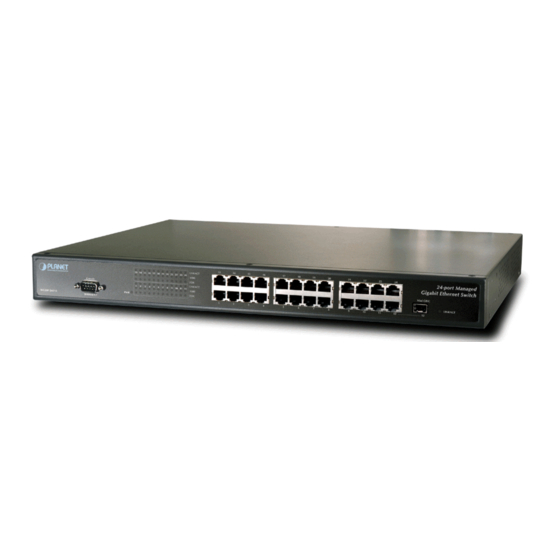
Basic knowledge of networking is assumed. Please read this chapter completely before continuing. 2.1 Product Description The WGSW-24010 is a powerful, high-performance 24G + 1 Mini-GBIC 10/100/1000Mbps Fast Ethernet and Gigabit managed switch with twenty-four 10/100/1000Mbps ports and 1-SFP Mini-GBIC interfaces. The SFP Mini-GBIC interfaces for fiber extension is ideal for backbone connection to other workgroup products. -
Page 9: I Nstalling The S Witch
Switch or the power adapter. 2.2 Installing the Switch This section describes how to install your WGSW-24010 Managed Gigabit Ethernet Switch and make connections to the Switch. Please read the following topics and perform the procedures in the order being presented. PLANET Managed Gigabit Ethernet Switch do not need software configuration. - Page 10 You must use the screws supplied with the mounting brackets. Damage caused to the parts by using incorrect screws would invalidate your warranty. Step3: Secure the brackets tightly. Step4: Follow the same steps to attach the second bracket to the opposite side. Step5: After the brackets are attached to the Switch, use suitable screws to securely attach the brackets to the rack, as shown in Figure 2-6 Figure 2-6 Mounting the Switch in a Rack...
-
Page 11: Console Configuration
Baud per second: 38400 § Data bits: 8 § Parity: None § Stop bits: 1 § Flow Control: None 3.2 Configure IP Address Power on the WGSW-24010, the terminal will display that it is running testing procedures. After boot, the following screen displayed. - Page 12 Figure 3-1 Console Main Screen of WGSW-24010 On “console>” prompt, enter “enable” to enable the privileged commands. The original prompt, “console>” will become “console#”. As show in Figure 3-2. Figure 3-2 Enable privileged commands 2. On “console#” prompt, enter “configure” to enter the configuration mode. The prompt “console#” then become ”console(config)#”.
- Page 13 4. On “console(config-if)#” prompt, enter “ip address A.B.C.D E.F.G.H” to add a new IP address. Note that A.B.C.D is your new IP address and E.F.G.H is needed for the subnet mask. For example, enter “ip address 192.168.16.234 255.255.255.0” will add a new IP address to WGSW-24010. As show in Figure 3-5. Figure 3-5 Add IP address 5.
-
Page 14: C Hange U Sername And P Assword
Figure 3-7 Show IP address 3.3 Change Username and Password For security reason, we strongly suggest that you change user name and password immediately. On “console#” prompt, enter “configure” to enter the configuration mode. The prompt “console#” then become”console(config)#”. On “console(config)#” prompt, enter “no username admin” to delete the default user. As show in Figure 3-8. Figure 3-8 Delete default user Enter “username AAAA password BBBB level N”... -
Page 15: S Ave C Onfiguration
3.4 Save Configuration The configurations you modified in console will save to next startup until you copy the running configuration to the startup configuration. Enter “exit” to exit the configuration mode. The prompt “console(config)#” will return to “console#”. Enter “copy running-config startup-config” on “console#” prompt to save the changes. As show in Figure 3-10. Figure 3-10 Copy running-config to startup-config You can also make a copy of the running configuration to a backup configuration. - Page 16 If you are not familiar with console command or the related parameter, enter “help” anytime Note in console to get the help description. See Appendix B for factory default configuration. Note...
-
Page 17: Web Configuration
4. WEB CONFIGURATION Besides the console interface, WGSW-24010 can be configured through an Ethernet connection, make sure the manager PC must be set on same the IP subnet address with the switch. For example, if you have changed the default IP address of the Switch to 192.168.16.234 with subnet mask 255.255.255.0 via console, then the manager PC should be set at 192.168.16.x (where x is a number between 2 and 254) with subnet... -
Page 18: C Onfigure S Ystem
Figure 3-14 main menu screen 4.2 Configure System The System section provides information for devining system parameters including security featrues, device software. Under system the folling topics are provided to devine and view the system informatin: General • SNTP • Logs •... -
Page 19: Assert
Asset The Asset page contains parameters for configuring general device information, including the system name, location, and contact, the system MAC Address, System Object ID, date, time, and System Up Time. To open Access screen perform the folling: Click System -> General -> Assert The Access information screen is displayed as in Figure 3-15. -
Page 20: Time Synchronization
Time Synchronization The Time Synchronization page contains fields for defining system time parameters for both the local hardware clock, and the external SNTP clock. If the system time is kept using an external SNTP clock, and the external SNTP clock fails, the system time reverts to the local hardware clock. - Page 21 • New Zealand -- From the first Sunday in October until the first Sunday on or after 15th March. • Norway -- Last weekend of March until the last weekend of October. • Paraguay -- From 6th April until 7th September. •...
- Page 22 The Clock Source section contains the following fields: The source used to set the system clock. The possible field values: • Clock Source -- Specifies that the system time is set via an SNTP server. For more information, see "SNTP Global •...
-
Page 23: Versions
• Week -- The week within the month at which DST ends every year. The possible field range is 1-5. • Month -- The month of the year in which DST ends every year. The possible field range is Jan.-Dec. •... -
Page 24: Sntp
Figure 3-18 Reset screen 4.2.2 SNTP The device supports the Simple Network Time Protocol (SNTP). SNTP assures accurate network device clock time synchronization up to the millisecond. Time synchronization is performed by a network SNTP server. SNTP operates only as a client, and cannot provide time services to other systems. The device can poll the following server types for the server time: •... -
Page 25: Sntp Global Settings
Polling for Anycast information is used when the server IP address is unknown. The first anycast server to return a response is used to set the time value. Time levels T3 and T4 are used to determine the server time. Using Anycast time information for synchronizing device time is preferred to using Broadcast time information. -
Page 26: Sntp Authentication
• Receive Anycast Servers Updates -- Polls the SNTP server for Anycast server time information, when enabled. If both the Receive Anycast Servers Update, and the Receive Broadcast Servers Update fields are enabled, the system time is set according the Anycast server time information. •... -
Page 27: Sntp Interface Settings
Click System -> SNTP -> Servers The SNTP Servers screen is displayed as in Figure 3-21. Figure 3-21 SNTP Servers screen The page includes the following fields: • SNTP Server -- Enter a user-defined SNTP server IP addresses or hostname. Up to eight SNTP servers can be defined. -
Page 28: Logs
Figure 3-22 SNTP Broadcast Interface Table screen The page includes the following fields: • Interface -- Contains an interface list on which SNTP can be enabled. • Receive Server Updates -- The amount of time that passes before the SNTP server is polled for information. The field range is 3600 - 4294967295 seconds. - Page 29 Critical The system is in a critical state. Cannot bind to SNMP. Error A system error has occurred. Failed to delete entry. Warning A system warning has Port down. occurred. Notice The system is functioning Bad route. properly, but system notice has occurred.
-
Page 30: Log File
Figure 3-23 RAM Log Tables Log File The Log File Table contains information about log entries saved to the Log File in FLASH, including the time the log was entered, the log severity, and a description of the log message. To open Log File Table screen perform the folling: Click System ->... -
Page 31: Remote Log Server
Figure 3-24 Log File Table screen The page includes the following fields: • Log Index -- The log number in the Log File Table. • Log Time -- Specifies the time at which the log was entered in the Log File Table. •... -
Page 32: Ip Addressing
4.2.4 IP Addressing The IP Addressing page contains links for assigning interface and default gateway IP addresses, and defining ARP and DHCP parameters for the interfaces. The IP Addressing page contains links to the following topics: • Default Gateway • IP Interface Parameters •... -
Page 33: Dhcp Ip Interface
To open IP Interface Parameter screen perform the folling: Click System -> IP Addressing -> IP Interface Parameter The IP Interface Parameter screen is displayed as in Figure 3-27. Figure 3-27 IP Interface Parameter screen The page includes the following fields: •... -
Page 34: Domain Name System
Figure 3-28 DHCP IP Interface screen The page includes the following fields: • Interface -- The specific interface connected to the device. Click the option button next to Port, LAG, or VLAN and select the interface connected to the device. •... -
Page 35: Default Domain Name
Figure 3-29 Domain Name System screen The page includes the following fields: • DNS Status -- Enables or disables translating DNS names into IP addresses. • DNS Server -- Contains a list of DNS servers. DNS servers are added in the Add DNS Server page. •... -
Page 36: Host Name Mapping
Figure 3-30 Default Domain Name screen The page includes the following fields: • Default Domain Name (1-158 characters) -- Contains a user-defined DNS domain name server. When selected, the DNS domain name is the default domain. • Type -- The domain type if the domain was statically or dynamically created. •... - Page 37 Figure 3-30 Host Name Mapping screen The page includes the following fields: • Host Name -- Contains a Host Name list. Host Name are defined in the Add Host Name Mapping page. Each host provides up to eight IP addresses. The field values for the Host Name field are: •...
-
Page 38: Diagnostics
Figure 3-31 ARP Settings screen The page includes the following fields: • Global Settings -- Select this option to activate the fields for ARP global settings. • ARP Entry Age Out (1-40000000) -- For all devices, the amount of time (seconds) that passes between ARP requests about an ARP table entry. -
Page 39: Integrated Cable Test
Integrated Cable Test The Integrated Cable Test for Copper Cables page contains fields for performing tests on copper cables. Cable testing provides information about where errors occurred in the cable, the last time a cable test was performed, and the type of cable error which occurred. -
Page 40: Management Security
4.2.6 Management Security The Management Security page provides access tosecurity pages that contain fields for setting security parameters for ports, device management methods, user, and server security. • Access Profiles • Authentication Profiles • Select Authentication • Local User Database •... -
Page 41: Authentication Profile
• Access Profile -- User-defined Access Profile lists. The Access Profile list contains a default value of Console List, to which user-defined access profiles are added. Selecting Console Only as the Access Profile name disconnects the session, and enables accessing the device from the console only. •... -
Page 42: Select Authentication
Figure 3-34 Authentication Profile screen The page includes the following fields: • Authentication Profile Name -- User-defined authentication profile lists to which user-defined authentication profiles are added. The defaults are Network Default and Console Default. • Optional Methods -- User authentication methods. Possible options are: •... -
Page 43: Local User Database
Figure 3-35 Select Authentication screen The page includes the following fields: • Console -- Authentication profiles used to authenticate console users. • Telnet -- Authentication profiles used to authenticate Telnet users. • Secure Telnet (SSH) -- Authentication profiles used to authenticate Secure Shell (SSH) users. SSH provides clients with secure and encrypted remote connections to a device. -
Page 44: Line Password
Figure 3-36 Local User Database screen The page includes the following fields: • User Name -- List of users. • Access Level -- User access level. The lowest user access level is 1, and the highest user access level is 15. •... -
Page 45: Enable Password
Figure 3-37 Line Password screen The page includes the following fields: • Line Password for Console/Telnet/Secure Telnet (0-159 Characters) -- The line password for accessing the device via a console, Telnet, or Secure Telnet session. Passwords can contain a maximum of 159 characters. •... -
Page 46: Tacacs
Figure 3-38 Enable Password screen The page includes the following fields: • Select Enable Access Level -- Access level associated with the enable password. Possible field values are 1-15. • Password (0-159 Characters) -- The currently configured enable password. Enable passwords can contain a maximum of 159 characters. - Page 47 Figure 3-39 TACACS+ Settings screen TACACS+ provides the following services: • Authentication -- Provides authentication during login and via user names and user-defined passwords. • Authorization -- Performed at login. Once the authentication session is completed, an authorization session starts using the authenticated user name. The TACACS server checks the user privileges. The TACACS+ protocol ensures network integrity through encrypted protocol exchanges between the device and TACACS+ server.
-
Page 48: Radius
Default Parameters Section The TACACS+ default parameters are user-defined defaults. The default settings are applied to newly defined TACACS+ servers. If default values are not defined, the system defaults are applied to the new TACACS+ new servers. The Default Parameters section contains the following fields: •... -
Page 49: Snmp
• Priority (1-65535) -- The server priority. The possible values are 1-65535, where 1 is the highest value. This is used to configure the order in which servers are queried. • Authentication Port -- Identifies the authentication port. The authentication port is used to verify the RADIUS server authentication. -
Page 50: Snmp Trap
The SNMP Communities screen is displayed as in Figure 3-41. Figure 3-41 SNMP Communities screen The page includes the following fields: • SNMP Management Station -- A list of management station IP addresses. • Community String -- Functions as a password and used to authenticate the selected management station to the device. -
Page 51: File Management
Figure 3-42 SNMP Trap Settings screen The page includes the following fields: • SNMP Trap -- Enables sending SNMP traps or SNMP notifications from the device to defined trap recipients. • Authentication Trap -- Enables sending SNMP traps when authentication failed to define recipients. •... - Page 52 Figure 3-43 File Download screen The page includes the following fields: • Firmware Download -- The Firmware file is downloaded. If Firmware Download is selected, the Configuration Download fields are grayed out. • Configuration Download -- The Configuration file is downloaded. If Configuration Download is selected, the Firmware Download fields are grayed out.
-
Page 53: File Upload
File Upload The File Upload to Server page contains fields for uploading the software from the TFTP server to the device. The Image file can also be uploaded from the File Upload to Server page. To open File Upload screen perform the folling: Click System ->... -
Page 54: Advanced Settings
The Copy Files screen is displayed as in Figure 3-45. Figure 3-45 Copy File screen The page includes the following fields: • Copy Configuration -- When selected, copies either the Running Configuration, Startup Configuration or Backup Configuration files. The possible field values are: •... -
Page 55: C Onfigure S Witch
Figure 3-46 General Settings screen The page includes the following fields: • Attribute -- The general setting attribute. • Current -- The currently configured value. • After Reset -- The future (after reset) value. By entering a value in the After Reset column, memory is allocated to the field table. -
Page 56: Network Security
4.3.1 Network Security The device enables network security through both Access Control Listsand Locked Ports. The Network Security page contains links to the following topics: • Port Based Authentication • Multiple Hosts • Authenticated Users • Port Security Port Base Authentication The Port Based Authentication page contains fields for configuring port based authentication. -
Page 57: Multiple Hosts
• Admin Interface Control -- Defines the port authorization state. The possible field values are: • Authorized -- Set the interface state to authorized (permit traffic). • Unauthorized -- Set the interface state to unauthorized (deny traffic). • Auto -- Authorize state is set by the authorization method. •... -
Page 58: Authentiated Users
• Port -- The port number for which Advanced Port Based Authentication is enabled. • Multiple Hosts -- Enables or disables a single host to authorize multiple hosts for system access. This setting must be enabled in order to either disable the ingress-filter, or to use port-lock security on the selected port. •... -
Page 59: Port Security
• User Name -- List of users authorized via the RADIUS Server. • Port -- The port number(s) used for authentication - per user name. • Session Time -- The amount of time the user was logged on to the device. The field format is Day:Hour:Minute:Seconds, for example, 3 days: 2 hours: 4 minutes: 39 seconds. -
Page 60: Ports
Figure 3-50 Port Security screen The page includes the following fields: • Interface -- The selected interface type on which Locked Port is enabled. • Port -- The selected interface type is a port. • LAG -- The selected interface type is a LAG. •... -
Page 61: Port Configuration
• Port Mirroring Port Configuration The Port Configuration page contains fields for defining port parameters. To open Port Configuration screen perform the folling: Click Switch -> Ports -> Port Configuration The Port Configuration screen is displayed as in Figure 3-51. Figure 3-51 Port Configuration screen The page includes the following fields: •... -
Page 62: Lag Configuration
• Auto Negotiation -- Enables Auto Negotiation on the port. Auto Negotiation is a protocol between two link partners that enables a port to advertise its transmission rate, duplex mode and flow control abilities to its partner. • Current Auto Negotiation -- The currently configured Auto Negotiation setting. •... -
Page 63: Storm Control
Figure 3-52 LAG Configure screen The page includes the following fields: • LAG -- The LAG number. • Description (0-64 Characters) -- Provides a user-defined description of the configured LAG. • LAG Type -- The port types that comprise the LAG. •... -
Page 64: Port Mirroring
The Storm Control page provides fields for enabling and configuring Storm Control. To open Storm Control screen perform the folling: Click Switch -> Ports -> Strom Control The Storm Control screen is displayed as in Figure 3-53. Figure 3-53 Storm Control screen The page includes the following fields: •... - Page 65 • The port is not a VLAN member. • Only one destination port can be defined. The following restrictions apply to ports configured to be source ports: • Source Ports cannot be a LAG member. • Ports cannot be configured as a destination port. •...
-
Page 66: Address Table
4.3.3 Address Table MAC addresses are stored in either the Static Address or the Dynamic Address databases. A packet addressed to a destination stored in one of the databases is forwarded immediately to the port. The Static and Dynamic Address Tables can be sorted by interface, VLAN, and interface type. -
Page 67: Dymanic Address Table
• Permanent -- The MAC address is permanent. • Delete on Reset -- The MAC address is deleted when the device is reset. • Delete on Timeout -- The MAC address is deleted when a timeout occurs. • Remove -- When selected, removes the the MAC address from the MAC Address Table. Dymanic Address Table The Dynamic Address Table contains fields for querying information in the dynamic address table, including the interface type, MAC addresses, VLAN, and table sorting. -
Page 68: Garp
4.3.4 GARP Generic Attribute Registration Protocol (GARP) is a general-purpose protocol that registers any network connectivity or membership-style information. GARP defines a set of devices interested in a given network attribute, such as VLAN or Multicast address. When configuring GARP, ensure the following: •... -
Page 69: Spanning Tree
4.3.5 Spanning Tree Spanning Tree Protocol (STP) provides tree topography for any arrangement of bridges. STP also provides one path between end stations on a network, eliminating loops. Loops occur when alternate paths exist between hosts. Loops in an extended network can cause bridges to forward traffic indefinitely, resulting in increased traffic and reducing network efficiency. -
Page 70: Stp Port Settings
• Enable -- Enables Spanning Tree • Disable -- Disables Spanning Tree • STP Operation Mode -- The STP mode by which STP is enabled on the device. The possible field values are: ú Classic STP -- Enables Classic STP on the device. This is the default value. ú... - Page 71 Figure 3-59 STP Port Settings screen The page includes the following fields: • Select a Port -- Port on which STP is enabled. • STP -- Enables or disables STP on the port. • Fast Link -- When selected, enables Fast Link mode for the port. If Fast Link mode is enabled for a port, the Port State is automatically placed in the Forwarding state when the port link is up.
-
Page 72: Stp Lag Settings
ú Gigabit Ethernet - 4 • Priority (0-240, in steps of 16) -- Priority value of the port. The priority value influences the port choice when a bridge has two ports connected in a loop. The priority value is between 0-240. The priority value is provided in increments of 16. -
Page 73: Rapid Spanning Tree
ú Listening -- The LAG is in the listening mode and cannot forward traffic or learn MAC addresses. ú Learning -- The LAG is in the learning mode and cannot forward traffic, but it can learn new MAC addresses. ú Forwarding -- The LAG is currently in the forwarding mode, and it can forward traffic and learn new MAC addresses. - Page 74 Figure 3-61 Rapid Spanning Tree screen The page includes the following fields: • Interface -- Port or LAG on which Rapid STP is enabled. • Role -- The port role assigned by the STP algorithm in order to provide to STP paths. The possible field values are: ú...
-
Page 75: Vlan
4.3.6 VLAN VLANs are logical subgroups of a Local Area Network (LAN) created via software rather than defining a hardware solution. VLANs combine user stations and network devices into a single domain regardless of the physical LAN segment to which they are attached. -
Page 76: Vlan Port Settings
The VLAN Membership page is divided into the following sections: • VLAN Membership Configuration • VLAN Port Membership Table VLAN Membership Configuration The VLAN Membership section contains parameters for assigning VLAN membership to ports. The section contains the following fields: •... -
Page 77: Vlan Lag Settings
Figure 3-63 VLAN Port Settings screen The page includes the following fields: • Port -- The port number included in the VLAN. • Port VLAN Mode -- The port mode. Possible values are: • General -- The port belongs to VLANs, and each VLAN is user-defined as tagged or untagged (full 802.1Q mode). -
Page 78: Portocol Group
Figure 3-64 VLAN LAG Settings The page includes the following fields: • LAG -- The LAG number included in the VLAN. • LAG VLAN Mode -- The LAG VLAN mode. Possible values are: • General -- The LAG belongs to VLANs, and each VLAN is user-defined as tagged or untagged (full 802.1Q mode). -
Page 79: Protocol Port Table
Figure 3-64 Protocol Group screen The page includes the following fields: Frame Type -- The packet type. Possible field values are Ethernet, RFC1042, and LLC Other. Protocol Value -- User-defined protocol name. Ethernet-Based Protocol Value -- The Ethernet protocol group type. The possible field values are IP, IPX and IPV6. Protocol Group ID -- The VLAN Group ID number. -
Page 80: Gvrp Parameters
Figure 3-65 Protocol Port Table screen The page includes the following fields: • Interface -- Port or LAG number added to a protocol group. • Group ID -- Protocol group ID to which the interface is added. Protocol group IDs are defined in the Protocol Group Table. -
Page 81: Link Agreegation
Figure 3-66 GVRP Global Parameters screen The page includes the following fields: • GVRP Global Status -- Enables or disables GVRP on the device. GVRP is disabled by default. • Interface -- The port or LAG for which GVRP is enabled. •... -
Page 82: Lacp Parameters
• The port's 802.1p priority is equal to LAGs 802.1p priority. • QoS Trust is not disabled on the port. • GVRP is not enabled. Ports can be configured as LACP ports only if the ports are not part of a previously configured LAG. Note The device uses a hash function to determine which frames are carried on which aggregated-link member. -
Page 83: Lag Membership
• Select a Port -- The port number to which timeout and priority values are assigned. • LACP Port Priority (1-65535) -- LACP priority value for the port. • LACP Timeout -- Administrative LACP timeout. The possible field values are: •... -
Page 84: Multicast Support
4.3.8 Multicast Support Multicast forwarding allows a single packet to be forwarded to multiple destinations. L2 Multicast service is based on L2 switch receiving a single packet addressed to a specific Multicast address. Multicast forwarding creates copies of the packet, and transmits the packets to the relevant ports. The device supports: •... -
Page 85: Bridge Multicast Group
Figure 3-69 Multicast Global Parameters The page includes the following fields: • Bridge Multicast Filtering -- Enables or disables bridge Multicast filtering. Disabled is the default value. IGMP Snooping can be enabled only if Bridge Multicast Filtering is enabled. • IGMP Snooping Status -- Enables or disables IGMP Snooping on the device. Disabled is the default value. Bridge Multicast Group The Bridge Multicast Group page displays the ports and LAGs attached to the Multicast service group in the Ports and LAGs tables. - Page 86 Figure 3-70 Bridge Multicast Group screen The page includes the following fields: • VLAN ID -- Identifies a VLAN and contains information about the Multicast group address. • Bridge Multicast Address -- Identifies the Multicast group MAC address/IP address. • Remove -- When selected, removes a Bridge Multicast address. •...
-
Page 87: Bridge Multicast Forward All
Toggle a port to F to forbid adding specific Multicast addresses to a specific port. Click Apply Changes. The port is assigned to the Multicast group, and the device is updated. Assigning LAGs to Receive Multicast Service Define the VLAN ID and the Bridge Multicast Address fields. Toggle the LAG to S to join the LAG to the selected Multicast group. -
Page 88: Igmp Snooping
Forbidden. Blank The port is not attached to a Multicast router or switch. Attaching a Port to a Multicast Router or Switch Define the VLAN ID field. Select a port in the Ports table, and assign the port a value. Click Apply Changes. -
Page 89: S Tatistics / Rmon I Nformation
• Host Timeout (1-2147483647) -- Time before an IGMP snooping entry is aged out. The default time is 260 seconds. • Multicast Router Timeout (1-2147483647) -- Time before aging out a Multicast router entry. The default value is 300 seconds. •... -
Page 90: Counter Summary
Figure 3-73 Utilization Summary screen The page includes the following fields: • Refresh Rate -- The amount of time that passes before the interface statistics are refreshed. • Interface -- The interface number. • Interface Status -- Status of the interface. •... -
Page 91: Interface Statistics
Figure 3-74 Counter Summary screen The page includes the following fields: • Refresh Rate -- The amount of time that passes before the interface statistics are refreshed. • Interface -- The interface number. • Interface Status -- The interface status. •... -
Page 92: Etherlink Statistics
Figure 3-75 Interface Statistics The Interface Statistics page is divided into the following sections: • Statistics Selection • Receive Statistics • Transmit Statistics Statistics Selection The Statistics Selection section contains the following fields: • Interface -- Specifies whether statistics are displayed for a port or LAG. •... -
Page 93: Gvrp Statistics
To open Etherlink Statistics screen perform the folling: Click Statics/RMON -> Table Views -> Etherlink Statistics The Etherlink Statistics screen is displayed as in Figure 3-76 Figure 3-76 Etherlink Statistics screen The page includes the following fields: • Interface -- Specifies whether statistics are displayed for a port or LAG. •... -
Page 94: Eap Statistics
The GVRP Statistics screen is displayed as in Figure 3-77 Figure 3-76 GVRP Statistics screen The Interface Statistics page is divided into the following sections: • Statistics Selection • GVRP Statistics Table Attribute (Counter) • GVRP Error Statistics Statistics Selection •... -
Page 95: Rmon
To open EAP Statistics screen perform the folling: Click Statics/RMON -> Table Views -> EAP Statistics The EAP Statistics screen is displayed as in Figure 3-78 Figure 3-78 EAP Statistics screen The page includes the following fields: • Port -- The port which is polled for statistics. •... -
Page 96: Rmon Statistics
• Statistics • History Control • History Table • Events Control • Events Log • Alarms RMON Statistics The RMON Statistics Group page contains fields for viewing information about device utilization and errors that occurred on the device. To open EAP Statistics screen perform the folling: Click Statics/RMON ->... -
Page 97: Rmon History Control
• CRC & Align Errors -- Number of CRC and Align errors that have occurred on the interface since the device was last refreshed. • Undersize Packets -- Number of undersized packets (less than 64 octets) received on the interface since the device was last refreshed. -
Page 98: Rmon History Table
• Remove -- When selected, removes the History Control Table entry. RMON History Table The RMON History Table contains interface specific statistical network samplings. Each table entry represents all counter values compiled during a single sample. To open RMON History Control screen perform the folling: Click Statics/RMON ->... -
Page 99: Rmon Events Control
• Utilization -- Estimates the main physical layer network usage on an interface during the session sampling. The value is reflected in hundredths of a percent. RMON Events Control The RMON Events Control page contains fields for defining RMON events. To open RMON History Control screen perform the folling: Click Statics/RMON ->... -
Page 100: Rmon Alarms
The RMON Events Log screen is displayed as in Figure 3-83 Figure 3-83 RMON Event Log screen The page includes the following fields: • Event -- The RMON Events Log entry number. • Log No.-- The log number. • Log Time -- Time when the log entry was entered. •... -
Page 101: Charts
Figure 3-84 RMON Alarm screen The page includes the following fields: • Alarm Entry -- Indicates a specific alarm. • Interface -- The interface for which RMON statistics are displayed. • Counter Name -- The selected MIB variable. • Counter Value -- B class=cBold origTag="Bold" cs="Bold"> The value of the selected MIB variable. •... -
Page 102: Ports
The Chart page contains links to the following topics: • Ports • LAGs Ports The Port Statistics page contains fields for opening statistics in a chart form for port elements. To open Port Statistics screen perform the folling: Click Statics/RMON -> Charts -> Ports The Ports Statistics screen is displayed as in Figure 3-85 Figure 3-85 Port Statistics screen The page includes the following fields:... -
Page 103: C Onfigure Q Uality Of S Ervice
Figure 3-86 LAG Statistics screen The page includes the following fields: • Interface Statistics -- Selects the type of interface statistics to open. • Etherlike Statistics -- Selects the type of Etherlike statistics to open. • RMON Statistics -- Selects the type of RMON statistics to open. •... -
Page 104: Qos Settings
QoS Settings The QoS Global Settings page contains fields for enabling or disabling QoS. In addition, the Trust mode can be selected. The Trust mode relies on predefined fields within the packet to determine the output queue. To open QoS Settings screen perform the folling: Click Quality of Service ->... -
Page 105: Interface Settings
Figure 3-88 Global Queue Settings screen The page includes the following fields: • Queues -- The Queue number. • Strict Priority -- Specifies if traffic scheduling is based strictly on the queue priority. The default is enabled. • WRR -- Specifies if traffic scheduling is based on the Weighted Round Robin (WRR) weights to egress queues Interface Settings The Interface Settings page contains fields for defining, per interface, if the selected Trust mode is to be activated. -
Page 106: Cos To Queue Mapping Table
Figure 3-89 Interface Cos/Qos Settings screen The page contains the following areas: • Interface Setting • Queue Settings Interface Settings Area The Interface Settings area includes the following fields: • Interface -- The specific port, LAG to configure: • Disable "Trust" Mode on Interface -- Disables Trust values on the device. For more information on Trust settings, see "Configuring Global CoS Settings". -
Page 107: Dscp To Queue Mapping
Click Quality of Service -> QoS Global Parameters -> CoS to Queue The CoS to Queue Mapping Table screen is displayed as in Figure 3-90 Figure 3-90 CoS to Queue Mapping Table The page includes the following fields: • Class of Service -- Specifies the CoS priority tag values, where zero is the lowest and 7 is the highest. •... - Page 108 Figure 3-91 DSCP to Queue Mapping The page includes the following fields: • DSCP In -- The values of the DSCP field within the incoming packet. • Queue -- The queue to which packets with the specific DSCP value is assigned. The values are 1-4, where one is the lowest value and four is the highest.
-
Page 109: Switch Operation
5. SWITCH OPERATION 5.1 Address Table The Switch is implemented with an address table. This address table composed of many entries. Each entry is used to store the address information of some node in network, including MAC address, port no, etc. This information comes from the learning process of Ethernet Switch. -
Page 110: Appendix A
APPENDIX A A.1 Switch‘s RJ-45 Pin Assignments 1000Mbps, 1000Base T Contact MDI-X BI_DA+ BI_DB+ BI_DA- BI_DB- BI_DB+ BI_DA+ BI_DC+ BI_DD+ BI_DC- BI_DD- BI_DB- BI_DA- BI_DD+ BI_DC+ BI_DD- BI_DC- Implicit implementation of the crossover function within a twisted-pair cable, or at a wiring panel, while not expressly forbidden, is beyond the scope of this standard. -
Page 111: Appendix B
APPENDIX B B.1 System Default configuration. The following file is the factory default settings of WGSW-24010. Once you have to reset your WGSW-24010 configuration to default values, please upload the file to replace the running/startup/backup configuration. no spanning-tree interface range ethernet all...
Need help?
Do you have a question about the WGSW-24010 and is the answer not in the manual?
Questions and answers