Table of Contents
Advertisement
Quick Links
Advertisement
Table of Contents

Subscribe to Our Youtube Channel
Related Manuals for Planet Networking & Communication igs-801m


Summary of Contents for Planet Networking & Communication igs-801m
-
Page 2: Fcc Warning
User’s Manual of IGS-801M Trademarks Copyright © PLANET Technology Corp. 2015. Contents are subject to revision without prior notice. PLANET is a registered trademark of PLANET Technology Corp. All other trademarks belong to their respective owners. Disclaimer PLANET Technology does not warrant that the hardware will work properly in all environments and applications, and makes no warranty and representation, either implied or expressed, with respect to the quality, performance, merchantability, or fitness for a particular purpose. -
Page 3: Table Of Contents
User’s Manual of IGS-801M TABLE OF CONTENTS 1. INTRODUCTION........................10 1.1 Packet Contents ............................10 1.2 Product Description ...........................11 1.3 How to Use This Manual ..........................12 1.4 Product Features............................13 1.5 Product Specifications ..........................16 2. INSTALLATION ........................19 2.1 Hardware Description ..........................19 2.1.1 Switch Front Panel ..............................19... - Page 4 User’s Manual of IGS-801M 4.2.1 System Information..............................40 4.2.2 IP Configurations ..............................41 4.2.3 IPv6 Configuration ...............................43 4.2.4 User Configuration...............................45 4.2.5 Time Settings...............................46 4.2.5.1 System Time..............................46 4.2.5.2 SNTP Server Settings ..........................49 4.2.6 Log Management..............................50 4.2.6.1 Local Log..............................50 4.2.6.2 Local Log..............................51 4.2.6.3 Remote Syslog ............................52 4.2.6.4 Log Message .............................54...
- Page 5 User’s Manual of IGS-801M 4.4.6 LAG Status ................................95 4.5 VLAN................................98 4.5.1 VLAN Overview ..............................98 4.5.2 IEEE 802.1Q VLAN .............................99 4.5.3 Management VLAN ............................103 4.5.4 Create VLAN ..............................104 4.5.5 Interface Settings...............................105 4.5.6 Port to VLAN..............................109 4.5.7 Port VLAN Membership ............................. 110 4.5.8 Protocol VLAN Group Setting ..........................
- Page 6 User’s Manual of IGS-801M 4.7.4.1 MLD Setting.............................162 4.7.4.2 MLD Static Group ............................164 4.7.4.3 MLD Group Table ............................165 4.7.4.4 MLD Router Setting ..........................165 4.7.4.5 MLD Router Table............................167 4.7.4.6 MLD Forward All ............................168 4.7.5 MLD Snooping Statics ............................169 4.7.6 Multicast Throttling Setting ..........................171 4.7.7 Multicast Filter ..............................172...
- Page 7 User’s Manual of IGS-801M 4.9.1.5 Authenticated Host ..........................206 4.9.2 RADIUS Server ..............................207 4.9.3 TACACS+ Server...............................210 4.9.4 AAA ...................................212 4.9.4.1 Login List ..............................213 4.9.4.2 Enable List...............................214 4.9.5 Access ................................215 4.9.5.1 Telnet ...............................215 4.9.5.2 SSH .................................216 4.9.5.3 HTTP ...............................218 4.9.5.4 HTTPs ..............................219 4.9.6 Management Access Method ..........................220...
- Page 8 User’s Manual of IGS-801M 4.9.12.2 Port Setting............................254 4.10 ACL ................................256 4.10.1 MAC-based ACL ..............................257 4.10.2 MAC-based ACE .............................258 4.10.3 IPv4-based ACL...............................261 4.10.4 IPv4-based ACE ..............................262 4.10.5 IPv6-based ACL...............................267 4.10.6 IPv6-based ACE ..............................268 4.10.7 ACL Binding ..............................273 4.11 MAC Address Table ..........................274 4.11.1 Static MAC Setting ............................275...
- Page 9 User’s Manual of IGS-801M 4.15 Maintenance............................313 4.15.1 Factory Default ..............................313 4.15.2 Reboot Switch ..............................313 4.15.3 Backup Manager .............................314 4.15.4 Upgrade Manager............................314 4.15.5 Dual Image ..............................316 5. SWITCH OPERATION ....................... 318 5.1 Address Table ............................318 5.2 Learning ..............................318 5.3 Forwarding & Filtering ..........................318 5.4 Store-and-Forward ...........................318...
-
Page 10: Introduction
User’s Manual of IGS-801M 1. INTRODUCTION Thank you for purchasing PLANET IGS-801M Industrial Managed Switch, which comes with multiple Gigabit Ethernet copper connectibility and robust layer 2 and layer 4 features. The description of this model is shown below: IGS-801M 8-Port 10/100/1000Mbps Managed Industrial Ethernet Switch “Industrial Managed Switch”... -
Page 11: Product Description
VLAN and Q-in-Q VLAN, Multiple Spanning Tree Protocol (MSTP), loop and BPDU guard, IGMP snooping, and MLD snooping. Via the link aggregation, the IGS-801M allows the operation of a high-speed trunk to combine with multiple ports, and supports fail-over as well. Also, the Link Layer Discovery Protocol (LLDP) is the Layer 2 protocol included to help... -
Page 12: How To Use This Manual
Powerful Security PLANET IGS-801M offers comprehensive IPv4/IPv6 Layer 2 to Layer 4 Access Control List (ACL) for enforcing security to the edge. It can be used to restrict network access by denying packets based on source and destination IP address, TCP/UDP ports or defined typical network applications. -
Page 13: Product Features
User’s Manual of IGS-801M 1.4 Product Features Physical Port 8-Port 10/100/1000BASE-T RJ45 copper Industrial Case / Installation IP30 metal case protection DIN-rail and wall mount design Redundant power design -12 to 48V DC, redundant power with polarity reverse protect function - AC 24V power adapter acceptable ... - Page 14 User’s Manual of IGS-801M Broadcast/Unknown unicast/Unknown multicast ■ Traffic classification IEEE 802.1p CoS TOS/DSCP/IP precedence of IPv4/IPv6 packets ■ Strict priority and Weighted Round Robin (WRR) CoS policies Multicast ■ Supports IPv4 IGMP snooping v2 and v3 ■ Supports IPv6 MLD snooping v1, v2 ■...
- Page 15 User’s Manual of IGS-801M Hardware reset button for system reboot or reset to factory default ■ SNTP Network Time Protocol ■ Cable diagnostics ■ Link Layer Discovery Protocol (LLDP) and LLDP-MED ■ SNMP trap for interface link up and link down notification ■...
-
Page 16: Product Specifications
User’s Manual of IGS-801M 1.5 Product Specifications Product IGS-801M Hardware Specifications Hardware Version Copper Ports 8 x 10/100/1000BASE-T RJ45 auto-MDI/MDI-X port Switch Architecture Store-and-Forward Switch Fabric 16Gbps/non-blocking Switch Throughput@64Bytes 11.9Mpps Address Table 8K entries Shared Data Buffer 4.1 megabits IEEE 802.3x pause frame for full-duplex... - Page 17 User’s Manual of IGS-801M Voice VLAN Protocol VLAN Private VLAN (Protected port) GVRP IEEE 802.3ad LACP and static trunk Link Aggregation Supports 8 trunk groups with 8 ports per trunk STP, IEEE 802.1D Spanning Tree Protocol RSTP, IEEE 802.1w Rapid Spanning Tree Protocol Spanning Tree Protocol MSTP, IEEE 802.1s Multiple Spanning Tree Protocol...
- Page 18 User’s Manual of IGS-801M RFC 3635 Ethernet-like MIB Standards Conformance Regulatory Compliance FCC Part 15 Class A, CE IEC60068-2-32 (Free fall) Stability Testing IEC60068-2-27 (Shock) IEC60068-2-6 (Vibration) IEEE 802.3 10BASE-T IEEE 802.3u 100BASE-TX IEEE 802.3ab Gigabit 1000BASE-T IEEE 802.3x flow control and back pressure IEEE 802.3ad port trunk with LACP...
-
Page 19: Installation
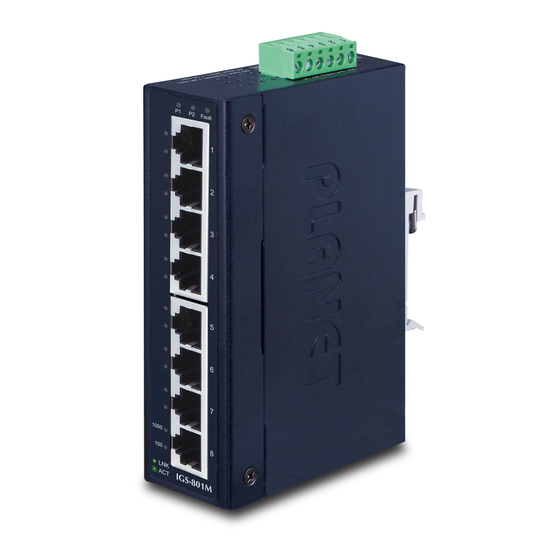
Managed Switch, please read this chapter completely. 2.1 Hardware Description 2.1.1 Switch Front Panel The front panel provides the monitoring of the Managed Switch’s simple interfaces. Figure 2-1 shows the front panel of the Industrial Managed Switch. Figure 2-1 IGS-801M Front Panel... -
Page 20: Led Indications
10/100/1000BASE-T Copper, RJ45 twisted-pair: Up to 100 meters. ■ Reset Button On the bottom of the IGS-801M, the reset button is designed to reboot the Industrial Managed Switch without turning off and on the power. The following is the summary table of the reset button functions:... -
Page 21: Switch Upper Panel
DC power inputs. Figure shows the upper panel of the switch. Figure 2-3: IGS-801M Upper Panel 2.1.4 Wiring the Power Inputs The 6-contact terminal block connector on the top panel of Industrial Managed Switch is used for two DC redundant power inputs. -
Page 22: Wiring The Fault Alarm Contact
User’s Manual of IGS-801M Tighten the wire-clamp screws for preventing the wires from loosening. Power 1 Fault Power 2 The wire gauge for the terminal block should be in the range between 12 and 24 AWG. 2.1.5 Wiring the Fault Alarm Contact The fault alarm contacts are in the middle of the terminal block connector as the picture shows below. - Page 23 User’s Manual of IGS-801M...
-
Page 24: Mounting Installation
User’s Manual of IGS-801M 2.2 Mounting Installation This section describes how to install your Industrial Managed Switch and make connections to the Industrial Managed Switch. Please read the following topics and perform the procedures in the order being presented. To install your Industrial Managed Switch on a desktop or shelf, simply complete the following steps. -
Page 25: Wall Mount Plate Mounting
User’s Manual of IGS-801M Step 3: Check whether the DIN-rail is tightly on the track. Step 4: Please refer to the following procedures to remove the Industrial Managed Switch from the track. Step 5: Lightly pull out the bottom of DIN-rail to remove it from the track. - Page 26 User’s Manual of IGS-801M Step 3: Use the screws to screw the wall mount plate on the Industrial Managed Switch. Step 4: Use the hook holes at the corners of the wall mount plate to hang the Industrial Managed Switch on the wall.
-
Page 27: Switch Management
User’s Manual of IGS-801M 3. SWITCH MANAGEMENT This chapter explains the methods that you can use to configure management access to the Industrial Managed Switch. It describes the types of management applications and the communication and management protocols that deliver data between your management device (workstation or personal computer) and the system. -
Page 28: Management Access Overview
User’s Manual of IGS-801M 3.2 Management Access Overview The Industrial Managed Switch gives you the flexibility to access and manage it using any or all of the following methods: Web browser interface An external SNMP-based network management application ... -
Page 29: Web Management
User’s Manual of IGS-801M 3.3 Web Management The Industrial Managed Switch offers management features that allow users to manage the Industrial Managed Switch from anywhere on the network through a standard browser such as Microsoft Internet Explorer. After you set up your IP address for the switch, you can access the Industrial Managed Switch's Web interface applications directly in your Web browser by entering the IP address of the Industrial Managed Switch. -
Page 30: Snmp-Based Network Management
User’s Manual of IGS-801M 3.4 SNMP-based Network Management You can use an external SNMP-based application to configure and manage the Industrial Managed Switch, such as SNMPc Network Manager, HP Openview Network Node Management (NNM) or What’s Up Gold. This management method requires the SNMP agent on the switch and the SNMP Network Management Station to use the same community string. - Page 31 User’s Manual of IGS-801M Figure 3-1-6: Planet Smart Discovery Utility Screen If there are two LAN cards or above in the same administrator PC, choose a different LAN card by using the “Select Adapter” tool. Press the “Refresh” button for the currently-connected devices in the discovery list as the screen shows below:...
- Page 32 User’s Manual of IGS-801M Update Multi: use current setting on multi-devices. Update All: use current setting on whole devices in the list. The same functions mentioned above also can be found in “Option” tools bar. To click the “Control Packet Force Broadcast” function, it allows you to assign a new setting value to the Web Smart Switch under a different IP subnet address.
-
Page 33: Web Configuration
User’s Manual of IGS-801M 4. WEB CONFIGURATION This section introduces the configuration and functions of the Web-based management. About Web-based Management The Industrial Managed Switch offers management features that allow users to manage the Industrial Managed Switch from anywhere on the network through a standard browser such as Microsoft Internet Explorer. - Page 34 User’s Manual of IGS-801M When the following login screen appears, please enter the default username "admin" with password “admin” (or the username and password you have changed via console) to login the main screen of Industrial Managed Switch. The login...
- Page 35 User’s Manual of IGS-801M Now, you can use the Web management interface to continue the switch management or manage the Industrial Managed Switch by Web interface. The Switch Menu on the left of the web page lets you access all the commands and statistics the Industrial Managed Switch provides.
-
Page 36: Main Web Page
User’s Manual of IGS-801M 4.1 Main Web Page The Industrial Managed Switch provides a Web-based browser interface for configuring and managing it. This interface allows you to access the Industrial Managed Switch using the Web browser of your choice. This chapter describes how to use the Industrial Managed Switch’s Web browser interface to configure and manage it. -
Page 37: Save Button
User’s Manual of IGS-801M Figure 4-1-5 Industrial Managed Switch Main Functions Menu Buttons : Click to save changes or reset to default. : Click to log out the Industrial Managed Switch. : Click to reboot the Industrial Managed Switch. : Click to refresh the page. -
Page 38: Configuration Manager
User’s Manual of IGS-801M The page includes the following fields: Object Description Save Configuration to Click to save the configuration. For more detailed information, please refer to FLASH chapter 4.1.2. Restore to Default Click to reset switch in default parameter. For more detailed information, please refer to chapter 4.15.1. -
Page 39: Saving Configuration
User’s Manual of IGS-801M configuration file to be startup-config. Backup Configuration The backup configuration is empty in FLASH; please save the backup configuration first by “Maintenance > Backup Manager”. Buttons : Click to save configuration. 4.1.2.1 Saving Configuration In the Industrial Managed Switch, the running configuration file stores in the RAM. In the current version, the running configuration sequence of running-config can be saved from the RAM to FLASH by ”Save Configurations to FLASH”... -
Page 40: System
User’s Manual of IGS-801M 4.2 System Use the System menu items to display and configure basic administrative details of the Industrial Managed Switch. Under System the following topics are provided to configure and view the system information. This section has the following items: ■... -
Page 41: Ip Configurations
User’s Manual of IGS-801M Object Description System Name Display the current system name System Location Display the current system location System Contact Display the current system contact MAC Address The MAC address of this Industrial Managed Switch. - Page 42 User’s Manual of IGS-801M The page includes the following fields: Object Description Indicates the IP address mode operation. Possible modes are: Mode Static: Enable NTP mode operation. When enabling NTP mode operation, the agent forwards and transfers NTP messages between the clients and the server when they are not on the same subnet domain.
-
Page 43: Ipv6 Configuration
User’s Manual of IGS-801M Object Description DHCP State Display the current DHCP state. IP Address Display the current IP address. Subnet Mask Display the current subnet mask. Gateway Display the current gateway. DNS Server 1/2 Display the current DNS server. - Page 44 User’s Manual of IGS-801M Gateway Provide the IPv6 gateway address of this switch. IPv6 address is in 128-bit records represented as eight fields of up to four hexadecimal digits with a colon separating each field (:). For example, 'fe80::215:c5ff:fe03:4dc7'.
-
Page 45: User Configuration
User’s Manual of IGS-801M 4.2.4 User Configuration This page provides an overview of the current users and privilege type. Currently the only way to login as another user on the Web server is to close and reopen the browser. After the setup is completed, please press the “Apply” button to take effect. -
Page 46: Time Settings
User’s Manual of IGS-801M Object Description Username Display the current username Password Type Display the current password type Privilege Type Display the current privilege type Modify Click to modify the local user entry : Delete the current user 4.2.5 Time Settings... - Page 47 User’s Manual of IGS-801M Manual Time To set time manually. Year - Select the starting Year. Month - Select the starting month. Day - Select the starting day. Hours - Select the starting hour. Minutes - Select the starting minute.
- Page 48 User’s Manual of IGS-801M Figure 4-2-9 Time Information Page Screenshot The page includes the following fields: Object Description Current Data/Time Display the current data/time SNTP Display the current SNTP state Time Zone Display the current time zone ...
-
Page 49: Sntp Server Settings
User’s Manual of IGS-801M 4.2.5.2 SNTP Server Settings The SNTP Server Configuration screens in Figure 4-2-10 & Figure 4-2-11 appear. Figure 4-2-10 SNTP Setup Page Screenshot The page includes the following fields: Object Description SNTP Server Address Type the IP address or domain name of the SNTP server ... -
Page 50: Log Management
User’s Manual of IGS-801M 4.2.6 Log Management The Industrial Managed Switch log management is provided here. The local logs allow you to configure and limit system messages that are logged to flash or RAM memory. The default is for event levels 0 to 3 to be logged to flash and levels 0 to 6 to be logged to RAM. -
Page 51: Local Log
User’s Manual of IGS-801M Figure 4-2-13 Logging Information Page Screenshot The page includes the following fields: Object Description Logging Service Display the current logging service status 4.2.6.2 Local Log The switch system local log information is provided here. The local Log screens in Figure 4-2-14 &... -
Page 52: Remote Syslog
User’s Manual of IGS-801M Buttons : Click to apply changes. Figure 4-2-15 Local Log Setting Status Page Screenshot The page includes the following fields: Object Description Status Display the current local log state Target Display the current local log target ... - Page 53 User’s Manual of IGS-801M The Remote Syslog screens in Figure 4-2-16 & Figure 4-2-17 appear. Figure 4-2-16 Remote Log Target Page Screenshot The page includes the following fields: Object Description Server Address Provide the remote syslog IP address of this switch.
-
Page 54: Log Message
User’s Manual of IGS-801M Server Info Display the current remote syslog server information Severity Display the current remote syslog severity Facility Display the current remote syslog facility Action : Delete the remote server entry 4.2.6.4 Log Message The switch log view is provided here. - Page 55 User’s Manual of IGS-801M Figure 4-2-19 Logging Information Page Screenshot The page includes the following fields: Object Description Target Display the current log target Severity Display the current log severity Category Display the current log category Total Entries...
-
Page 56: Snmp Management
User’s Manual of IGS-801M 4.2.7 SNMP Management 4.2.7.1 SNMP Overview The Simple Network Management Protocol (SNMP) is an application layer protocol that facilitates the exchange of management information between network devices. It is part of the Transmission Control Protocol/Internet Protocol (TCP/IP) protocol suite. -
Page 57: Snmp System Information
User’s Manual of IGS-801M 4.2.7.2 SNMP System Information Configure SNMP setting on this page. The SNMP System global setting screens in Figure 4-2-21 & Figure 4-2-22 appear. Figure 4-2-21 SNMP Global Setting Page Screenshot The page includes the following fields:... - Page 58 User’s Manual of IGS-801M Figure 4-2-23 SNMPv3 View Table Setting Page Screenshot The page includes the following fields: Object Description View Name A string identifying the view name that this entry should belong to. The allowed string length is 1 to 16.
-
Page 59: Snmp Access Group
User’s Manual of IGS-801M Object Description Display the current SNMP view name View Name Subtree OID Display the current SNMP subtree OID OID Mask Display the current SNMP OID mask View Type Display the current SNMP view type ... - Page 60 User’s Manual of IGS-801M Read View Name Read view name is the name of the view in which you can only view the contents of the agent. The allowed string length is 1 to 16. Write View Name Write view name is the name of the view in which you enter data and configure the contents of the agent.
-
Page 61: Snmp Community
User’s Manual of IGS-801M 4.2.7.5 SNMP Community Configure SNMP Community on this page. The SNMP Community screens in Figure 4-2-27 & Figure 4-2-28 appear. Figure 4-2-27 Community Setting Page Screenshot The page includes the following fields: Object Description Indicates the community read/write access string to permit access to SNMP Community Name agent. -
Page 62: Snmp User
User’s Manual of IGS-801M The page includes the following fields: Object Description Community Name Display the current community type Group Name Display the current SNMP access group’s name View Name Display the current view name Access Right Display the current access type ... - Page 63 User’s Manual of IGS-801M MD5: An optional flag to indicate that this user using MD5 authentication protocol. SHA: An optional flag to indicate that this user using SHA authentication protocol. The value of security level cannot be modified if entry already exists. That means you must first ensure that the value is set correctly.
-
Page 64: Snmpv1, 2 Notification Recipients
User’s Manual of IGS-801M 4.2.7.7 SNMPv1, 2 Notification Recipients Configure SNMPv1 and 2 notification recipients on this page. The SNMPv1, 2 Notification Recipients screens in Figure 4-2-31 & Figure 4-2-32 appear. Figure 4-2-31 SNMPv1, 2 Notification Recipients Page Screenshot The page includes the following fields:... -
Page 65: Snmpv3 Notification Recipients
User’s Manual of IGS-801M The page includes the following fields: Object Description Display the current server address Server Address SNMP Version Display the current SNMP version Notify Type Display the current notify type Community Name Display the current community name ... -
Page 66: Snmp Engine Id
User’s Manual of IGS-801M : Click to add a new SNMPv3 host entry. Figure 4-2-34 SNMPv3 Host Status Page Screenshot The page includes the following fields: Object Description Server Address Display the current server address Notify Type Display the current notify type ... -
Page 67: Snmp Remote Engine Id
User’s Manual of IGS-801M Buttons : Click to apply changes. Figure 4-2-36 SNMPv3 Engine ID Status Page Screenshot The page includes the following fields: Object Description User Default Display the current status Engine ID Display the current engine ID 4.2.7.10 SNMP Remote Engine ID... - Page 68 User’s Manual of IGS-801M The page includes the following fields: Object Description Remote IP Address Indicates the SNMP remote engine ID address. It allows a valid IP address in dotted decimal notation ('x.y.z.w'). Engine ID An octet string identifying the engine ID that this entry should belong to.
-
Page 69: Port Management
User’s Manual of IGS-801M 4.3 Port Management Use the Port Menu to display or configure the Industrial Managed Switch's ports. This section has the following items: Configures port configuration settings Port Configuration Port Counters Lists Ethernet and RMON port statistics ... - Page 70 User’s Manual of IGS-801M Speed Select any available link speed for the given switch port. Draw the menu bar to select the mode. Auto - Setup Auto negotiation. Auto-10M - Setup 10M Auto negotiation. Auto-100M - Setup 100M Auto negotiation.
-
Page 71: Port Counters
User’s Manual of IGS-801M Object Description This is the logical port number for this row Port Description Click to indicate the port name Enable State Display the current port state Display the current link status Link Status ... - Page 72 User’s Manual of IGS-801M Figure 4-3-4 Interface Counters Page Screenshot Object Description Received Octets The total number of octets received on the interface, including framing characters. Received Unicast The number of subnetwork-unicast packets delivered to a higher-layer protocol.
- Page 73 User’s Manual of IGS-801M Received Broadcast The number of packets, delivered by this sub-layer to a higher (sub-) layer, Packets addressed to a broadcast address at this sub-layer. Transmit Multicast The total number of packets that higher-level protocols requested is transmitted...
- Page 74 User’s Manual of IGS-801M operating in full-duplex mode. Frame Too Long A count of frames received on a particular interface that exceeds the maximum permitted frame size. Symbol Errors The number of received and transmitted symbol errors Control In Unknown...
- Page 75 User’s Manual of IGS-801M Multicast Packets The total number of good frames received that were directed to this multicast address. CRC / Alignment The number of CRC/alignment errors (FCS or alignment errors). Errors Undersize Packets The total number of frames received that were less than 64 octets long(excluding framing bits, but including FCS octets) and were otherwise well formed.
-
Page 76: Bandwidth Utilization
User’s Manual of IGS-801M 4.3.3 Bandwidth Utilization The Bandwidth Utilization page displays the percentage of the total available bandwidth being used on the ports. Bandwidth utilization statistics can be viewed using a line graph. The Bandwidth Utilization screen in Figure 4-3-7 appears. -
Page 77: Port Mirroring
User’s Manual of IGS-801M 4.3.4 Port Mirroring Configure port Mirroring on this page. This function provides monitoring of network traffic that forwards a copy of each incoming or outgoing packet from one port of a network switch to another port where the packet can be studied. It enables the manager to keep close track of switch performance and alter it if necessary. - Page 78 User’s Manual of IGS-801M The page includes the following fields: Object Description Session ID Set the port mirror session ID. Possible ID are: 1 to 4. Monitor Session State Enable or disable the port mirroring function. Destination Port Select the port to mirror destination port.
-
Page 79: Jumbo Frame
User’s Manual of IGS-801M 4.3.5 Jumbo Frame This page provides to select the maximum frame size allowed for the switch port. The Jumbo Frame screen in Figure 4-3-11 & Figure 4-3-12 appear. Figure 4-3-11 Jumbo Frame Setting Page Screenshot The page includes the following fields:... -
Page 80: Port Error Disabled Configuration
User’s Manual of IGS-801M 4.3.6 Port Error Disabled Configuration This page provides to set port error disable function. The Port Error Disable Configuration screens in Figure 4-3-13 & Figure 4-3-14 appear. Figure 4-3-13 Error Disabled Recovery Page Screenshot The page includes the following fields:... - Page 81 User’s Manual of IGS-801M Buttons : Click to apply changes. Figure 4-3-14 Error Disabled Information Page Screenshot The page includes the following fields: Object Description Recovery Interval Display the current recovery interval time BPDU Guard Display the current BPDU guard status ...
-
Page 82: Port Error Disabled
User’s Manual of IGS-801M 4.3.7 Port Error Disabled This page provides disable that transitions a port into error disable and the recovery options. The ports were disabled by some protocols such as BPDU Guard, Loopback and UDLD. The Port Error Disable screen in Figure 4-3-15 appears. - Page 83 User’s Manual of IGS-801M For protected port group to be applied, the Industrial Managed switch must first be configured for standard VLAN operation. Ports in a protected port group fall into one of these two groups: Promiscuous (Unprotected) ports —...
- Page 84 User’s Manual of IGS-801M Figure 4-3-16 Protected Ports Settings Page Screenshot The page includes the following fields: Object Description Port List Select port number from this drop-down list. Port Type Displays protected port types. - Protected: A single stand-alone VLAN that contains one promiscuous port and one or more isolated (or host) ports.
-
Page 85: Eee
User’s Manual of IGS-801M 4.3.9 EEE What is EEE EEE is a power saving option that reduces the power usage when there is low or no traffic utilization.EEE works by powering down circuits when there is no traffic. When a port gets data to be transmitted all circuits are powered up. The time it takes to power up the circuits is named wakeup time. - Page 86 User’s Manual of IGS-801M Figure 4-3-19 EEE Enable Status Page Screenshot The page includes the following fields: Object Description Port The switch port number of the logical port EEE State Display the current EEE state...
-
Page 87: Link Aggregation
User’s Manual of IGS-801M 4.4 Link Aggregation Port Aggregation optimizes port usage by linking a group of ports together to form a single Link Aggregated Groups (LAGs). Port Aggregation multiplies the bandwidth between the devices, increases port flexibility, and provides link redundancy. - Page 88 User’s Manual of IGS-801M The Link Aggregation Control Protocol (LACP) provides a standardized means for exchanging information between Partner Systems that require high-speed redundant links. Link aggregation lets you group up to eight consecutive ports into a single dedicated connection. This feature can expand bandwidth to a device on the network. LACP operation requires full-duplex mode.
-
Page 89: Lag Setting
User’s Manual of IGS-801M 4.4.1 LAG Setting This page allows configuring load balance algorithm configuration settings. The LAG Setting screens in Figure 4-4-2 & Figure 4-4-3 appear. Figure 4-4-2 LAG Setting Page Screenshot The page includes the following fields: Object Description ... -
Page 90: Lag Management
User’s Manual of IGS-801M 4.4.2 LAG Management This page is used to configure the LAG management. The LAG Management screens in Figure 4-4-4 & Figure 4-4-5 appear. Figure 4-4-4 LAG Management Page Screenshot The page includes the following fields: Object Description ... -
Page 91: Lag Port Setting
User’s Manual of IGS-801M The page includes the following fields: Object Description The LAG for the settings contained in the same row Name Display the current name Type Display the current type Link State Display the link state ... - Page 92 User’s Manual of IGS-801M Auto-1000M - Set up 1000M Auto negotiation. Auto-10/100M – Set up 10/100M Auto negotiation. 10M – Set up 10M Force mode. 100M – Set up 100M Force mode. 1000M – Set up 1000M Force mode.
-
Page 93: Lacp Setting
User’s Manual of IGS-801M Duplex Display the current duplex mode Flow Control Config Display the current flow control configuration Flow Control Status Display the current flow control status 4.4.4 LACP Setting This page is used to configure the LACP system priority setting. The LACP Setting screens in Figure 4-4-8 &... -
Page 94: Lacp Port Setting
User’s Manual of IGS-801M 4.4.5 LACP Port Setting This page is used to configure the LACP port setting. The LACP Port Setting screens in Figure 4-4-10 & Figure 4-4-11 appear. Figure 4-4-10 LACP Port Setting Page Screenshot The page includes the following fields:... -
Page 95: Lag Status
User’s Manual of IGS-801M Object Description Port Name The switch port number of the logical port Display the current LACP priority parameter Priority Timeout Display the current timeout parameter 4.4.6 LAG Status This page displays LAG status. The LAG Status screens in Figure 4-4-12 &... - Page 96 User’s Manual of IGS-801M Figure 4-4-13 LACP Information Page Screenshot The page includes the following fields: Object Description Trunk Display the current trunk ID Port Display the current port number PartnerSysId The system ID of link partner. This field would be updated when the port receives LACP PDU from link partner ...
- Page 97 User’s Manual of IGS-801M “Aggregation”, “Synchronization”, “Collecting”, “Distributing”, “Defaulted”, and “Expired”. The contents could be true or false. If the contents are false, the web shows “_”; if the contents are true, the web shows “A”, “T”, “G”, “S”, “C”, “D”, “F” and “E” for each content respectively.
-
Page 98: Vlan
User’s Manual of IGS-801M 4.5 VLAN 4.5.1 VLAN Overview A Virtual Local Area Network (VLAN) is a network topology configured according to a logical scheme rather than the physical layout. VLAN can be used to combine any collection of LAN segments into an autonomous user group that appears as a single LAN. -
Page 99: Ieee 802.1Q Vlan
User’s Manual of IGS-801M This section has the following items: Management VLAN Configures the management VLAN Create VLAN Creates the VLAN group Interface Settings Configures mode and PVID on the VLAN port Port to VLAN Configures the VLAN membership ... - Page 100 User’s Manual of IGS-801M ■ IEEE 802.1Q Standard IEEE 802.1Q (tagged) VLAN are implemented on the Switch. 802.1Q VLAN require tagging, which enables them to span the entire network (assuming all switches on the network are IEEE 802.1Q-compliant). VLAN allow a network to be segmented in order to reduce the size of broadcast domains. All packets entering a VLAN will only be forwarded to the stations (over IEEE 802.1Q enabled switches) that are members of that VLAN, and this includes broadcast,...
-
Page 101: Port Vlan Id
User’s Manual of IGS-801M The Ether Type and VLAN ID are inserted after the MAC source address, but before the original Ether Type/Length or Logical Link Control. Because the packet is now a bit longer than it was originally, the Cyclic Redundancy Check (CRC) must be recalculated. -
Page 102: Assigning Ports To Vlans
User’s Manual of IGS-801M ■ Assigning Ports to VLANs Before enabling VLANs for the switch, you must first assign each port to the VLAN group(s) in which it will participate. By default all ports are assigned to VLAN 1 as untagged ports. Add a port as a tagged port if you want it to carry traffic for one or more VLANs, and any intermediate network devices or the host at the other end of the connection supports VLANs. -
Page 103: Management Vlan
User’s Manual of IGS-801M 4.5.3 Management VLAN Configure Management VLAN on this page. The screens in Figure 4-5-1 & Figure 4-5-2 appear. Figure 4-5-1 Management VLAN Setting Page Screenshot The page includes the following fields: Object Description Management VLAN... -
Page 104: Create Vlan
User’s Manual of IGS-801M 4.5.4 Create VLAN Create/delete VLAN on this page. The screens in Figure 4-5-3 & Figure 4-5-4 appear. Figure 4-5-3 VLAN Setting Page Screenshot The page includes the following fields: Object Description Indicates the ID of this particular VLAN. -
Page 105: Interface Settings
User’s Manual of IGS-801M 4.5.5 Interface Settings This page is used for configuring the Industrial Managed Switch port VLAN. The VLAN per Port Configuration Page contains fields for managing ports that are part of a VLAN. The port default VLAN ID (PVID) is configured on the VLAN Port Configuration Page. - Page 106 User’s Manual of IGS-801M configurations, require intensive processing of VLAN mapping tables, and could easily exceed the maximum VLAN limit of 4096. The Industrial Managed Switch supports multiple VLAN tags and can therefore be used in MAN applications as a provider bridge, aggregating traffic from numerous independent customer LANs into the MAN (Metro Access Network) space.
- Page 107 User’s Manual of IGS-801M The page includes the following fields: Object Description Port Select Select port number from this drop-down list to set VLAN port setting. Interface VLAN Mode Set the port in access, trunk, hybrid and tunnel mode.
- Page 108 User’s Manual of IGS-801M Figure 4-5-6 Edit Interface Setting Page Screenshot The page includes the following fields: Object Description The switch port number of the logical port Port Interface VLAN Mode Display the current interface VLAN mode PVID Display the current PVID ...
-
Page 109: Port To Vlan
User’s Manual of IGS-801M 4.5.6 Port to VLAN Use the VLAN Static Table to configure port members for the selected VLAN index. This page allows you to add and delete port members of each VLAN. The screen in Figure 4-5-7 appears. -
Page 110: Port Vlan Membership
User’s Manual of IGS-801M port will be untagged, that is, not carry a tag and therefore not carry VLAN or CoS information. Note that an interface must be assigned to at least one group as an untagged port. PVID... -
Page 111: Protocol Vlan Group Setting
User’s Manual of IGS-801M 4.5.8 Protocol VLAN Group Setting The network devices required to support multiple protocols cannot be easily grouped into a common VLAN. This may require non-standard devices to pass traffic between different VLANs in order to encompass all the devices participating in a specific protocol. - Page 112 User’s Manual of IGS-801M Valid values for frame type ranges from 0x0600-0xfffe Buttons : Click to apply changes. Figure 4-5-10 Protocol VLAN Group State Page Screenshot The page includes the following fields: Object Description Group ID Display the current group ID ...
-
Page 113: Protocol Vlan Port Setting
User’s Manual of IGS-801M 4.5.9 Protocol VLAN Port Setting This page allows you to map an already configured Group Name to a VLAN/port for the switch. The Protocol VLAN Port Setting/State screens in Figure 4-5-11 & Figure 4-5-12 appear. Figure 4-5-11 Protocol VLAN Port Setting Page Screenshot... -
Page 114: Gvrp Setting
User’s Manual of IGS-801M 4.5.10 GVRP Setting GARP VLAN Registration Protocol (GVRP) defines a way for switches to exchange VLAN information in order to register VLAN members on ports across the network. VLANs are dynamically configured based on join messages issued by host devices and propagated throughout the network. - Page 115 User’s Manual of IGS-801M The page includes the following fields: Object Description GVRP Controls whether GVRP is enabled or disabled on this switch. Join Timeout The interval between transmitting requests/queries to participate in a VLAN group. Range: 20-16375 centiseconds Default: 20 centiseconds ...
-
Page 116: Gvrp Port Setting
User’s Manual of IGS-801M Object Description Display the current GVRP status GVRP Status Join Timeout Display the current join timeout parameter Leave Timeout Display the current leave timeout parameter LeaveAll Timeout Display the current leaveall timeout parameter 4.5.11 GVRP Port Setting... -
Page 117: Gvrp Vlan
User’s Manual of IGS-801M Figure 4-5-16 GVRP Port Status Page Screenshot The page includes the following fields: Object Description The switch port number of the logical port Port Enable Status Display the current GVRP port state Registration Mode Display the current registration mode ... -
Page 118: Gvrp Statistics
User’s Manual of IGS-801M 4.5.13 GVRP Statistics The GVRP Port Statistics and Error Statistics screens in Figure 4-5-18 & Figure 4-5-19 appear. Figure 4-5-18 GVRP Port Statistics Page Screenshot The page includes the following fields: Object Description Port The switch port number of the logical port ... - Page 119 User’s Manual of IGS-801M The page includes the following fields: Object Description Port The switch port number of the logical port. Invalid Protocol ID Display the current invalid protocol ID Invalid Attribute Type Display the current invalid attribute type ...
-
Page 120: Vlan Setting Example
User’s Manual of IGS-801M 4.5.14 VLAN setting example: - Separate VLANs - 802.1Q VLAN Trunk 4.5.14.1 Two separate 802.1Q VLANs The diagram shows how the Industrial Managed Switch handles Tagged and Untagged traffic flow for two VLANs. VLAN Group 2 and VLAN Group 3 are separated VLANs. Each VLAN isolates network traffic so only members of the VLAN receive traffic from the same VLAN members. - Page 121 User’s Manual of IGS-801M While the packet leaves Port-2, it will be stripped away its tag becoming an untagged packet. While the packet leaves Port-3, it will keep as a tagged packet with VLAN Tag=2. Tagged packet entering VLAN 2 ...
- Page 122 User’s Manual of IGS-801M Assign Tagged/Untagged to each port: VLAN ID = 2: Port-1 & 2 = Untagged, Port-3 = Tagged, Port -4~6 = Excluded. VLAN ID = 3: Port-4 & 5 = Untagged, Port -6 = Tagged, Port-1~3 = Excluded.
-
Page 123: Vlan Trunking Between Two 802.1Q Aware Switches
User’s Manual of IGS-801M 4.5.14.2 VLAN Trunking between two 802.1Q aware switches In most cases, they are used for “Uplink” to other switches. VLANs are separated at different switches, but they need to access other switches within the same VLAN group. The screen in Figure 4-5-21 appears. - Page 124 User’s Manual of IGS-801M Assign VLAN mode and PVID to each port: Port-1,Port-2 and Port-3 : VLAN Mode = Hybrid, PVID=2 Port-4,Port-5 and Port-6 : VLAN Mode = Hybrid, PVID=3 Port-7 : VLAN Mode = Hybrid, PVID=1 Assign Tagged/Untagged to each port:...
- Page 125 User’s Manual of IGS-801M VLAN ID = 3: Port-4 & 5 = Untagged, Port -6 & 7= Tagged, Port-1~3 = Excluded.
-
Page 126: Spanning Tree Protocol
User’s Manual of IGS-801M 4.6 Spanning Tree Protocol 4.6.1 Theory The Spanning Tree Protocol can be used to detect and disable network loops, and to provide backup links between switches, bridges or routers. This allows the switch to interact with other bridging devices in your network to ensure that only one route exists between any two stations on the network, and provide backup links which automatically take over when a primary link goes down. - Page 127 User’s Manual of IGS-801M The port identifier of the transmitting port The switch sends BPDUs to communicate and construct the spanning-tree topology. All switches connected to the LAN on which the packet is transmitted will receive the BPDU. BPDUs are not directly forwarded by the switch, but the receiving switch uses the information in the frame to calculate a BPDU, and, if the topology changes, initiates a BPDU transmission.
- Page 128 User’s Manual of IGS-801M From disabled to blocking Figure 4-6-1 STP Port State Transitions You can modify each port state by using management software. When you enable STP, every port on every switch in the network goes through the blocking state and then transitions through the states of listening and learning at power up. If properly configured, each port stabilizes to the forwarding or blocking state.
- Page 129 User’s Manual of IGS-801M except by setting priority The Bridge Identifier consists of two parts: below) a 16-bit priority and a 48-bit Ethernet MAC address 32768 + MAC Priority A relative priority for each switch – lower 32768 numbers give a higher priority and a greater...
- Page 130 User’s Manual of IGS-801M Hello Time – The Hello Time can be from 1 to 10 seconds. This is the interval between two transmissions of BPDU packets sent by the Root Bridge to tell all other Switches that it is indeed the Root Bridge. If you set a Hello Time for your Switch, and it is not the Root Bridge, the set Hello Time will be used if and when your Switch becomes the Root Bridge.
- Page 131 User’s Manual of IGS-801M Figure 4-6-2 Before Applying the STA Rules In this example, only the default STP values are used. Figure 4-6-3 After Applying the STA Rules...
- Page 132 User’s Manual of IGS-801M The switch with the lowest Bridge ID (switch C) was elected the root bridge, and the ports were selected to give a high port cost between switches B and C. The two (optional) Gigabit ports (default port cost = 20,000) on switch A are connected to one (optional) Gigabit port on both switch B and C.
-
Page 133: Stp Global Settings
User’s Manual of IGS-801M 4.6.2 STP Global Settings This page allows you to configure STP system settings. The settings are used by all STP Bridge instances in the Switch. The Industrial Managed Switch support the following Spanning Tree protocols: ‧ Compatiable -- Spanning Tree Protocol (STP):Provides a single path between end stations, avoiding and eliminating loops. - Page 134 User’s Manual of IGS-801M RSTP-Operation and MSTP-Operation. Configuration Name Identifier used to identify the configuration currently being used. Configuration Revision Identifier used to identify the configuration currently being used. The values allowed are between 0 and 65535. The default value is 0.
-
Page 135: Stp Port Setting
User’s Manual of IGS-801M 4.6.3 STP Port Setting This page allows you to configure per port STP settings. The STP Port Setting screens in Figure 4-6-6 & Figure 4-6-7 appear. Figure 4-6-6 STP Port Configuration Page Screenshot The page includes the following fields:... - Page 136 User’s Manual of IGS-801M the appropriate BPDU format (RSTP or STP-compatible) to send on the selected interfaces. (Default: Disabled) Buttons : Click to apply changes. By default, the system automatically detects the speed and duplex mode used on each port, and configures the path cost according to the values shown below.
- Page 137 User’s Manual of IGS-801M Figure 4-6-7 STP Port Status Page Screenshot The page includes the following fields: Object Description The switch port number of the logical STP port. Port Admin Enable Display the current STP port mode status ...
-
Page 138: Cist Instance Setting
User’s Manual of IGS-801M 4.6.4 CIST Instance Setting This Page allows you to configure CIST instance settings. The CIST Instance Setting and Information screens in Figure 4-6-8 & Figure 4-6-9 appear. Figure 4-6-8: CIST Instance Setting Page Screenshot The Page includes the following fields:... - Page 139 User’s Manual of IGS-801M The number of BPDU's a bridge port can send per second. Tx Hold Count When exceeded, transmission of the next BPDU will be delayed. Valid values are in the range 1 to 10 BPDU's per second.
-
Page 140: Cist Port Setting
User’s Manual of IGS-801M 4.6.5 CIST Port Setting This page allows you to configure per port CIST priority and cost. The CIST Port Setting and Status screens in Figure 4-6-10 & Figure 4-6-11 appear. Figure 4-6-10 CIST Port Setting Page Screenshot... - Page 141 User’s Manual of IGS-801M Figure 4-6-11 CIST Port Status Page Screenshot The page includes the following fields: Object Description Port The switch port number of the logical STP port Identifier (Priority / Display the current identifier (Priority / Port ID) Port ID) ...
-
Page 142: Mst Instance Configuration
User’s Manual of IGS-801M 4.6.6 MST Instance Configuration This page allows the user to configure MST Instance Configuration. The MST Instance Setting, Information and Status screens Figure 4-6-12, Figure 4-6-13 & Figure 4-6-14 appear. Figure 4-6-12 MST Instance Setting Page Screenshot... - Page 143 User’s Manual of IGS-801M VLAN List Display the current VLAN list VLAN Count Display the current VLAN count Priority Display the current MSTI priority Figure 4-6-14 MST Instance Status Page Screenshot The page includes the following fields:...
-
Page 144: Mst Port Setting
User’s Manual of IGS-801M 4.6.7 MST Port Setting This page allows the user to inspect the current STP MSTI port configurations, and possibly change them as well. A MSTI port is a virtual port, which is instantiated separately for each active CIST (physical) port for each MSTI instance configured and applicable for the port. - Page 145 User’s Manual of IGS-801M Figure 4-6-16 MST Port Status Page Screenshot The page includes the following fields: Object Description MSTI ID Display the current MSTI ID Port The switch port number of the logical STP port Identifier (Priority /...
-
Page 146: Stp Statistics
User’s Manual of IGS-801M 4.6.8 STP Statistics This page displays STP statistics. The STP statistics screen in Figure 4-6-17 appears. Figure 4-6-17 STP Statistics Page Screenshot The page includes the following fields: Object Description Port The switch port number of the logical STP port ... -
Page 147: Multicast
User’s Manual of IGS-801M 4.7 Multicast This section has the following items: Properties Configures multicast properties IGMP Snooping Configures IGMP snooping settings IGMP Snooping Statistics Display the IGMP snooping statistics MLD Snooping Configures MLD snooping settings ... -
Page 148: Igmp Snooping
User’s Manual of IGS-801M Figure 4-7-2 Properties Information Page Screenshot The page includes the following fields: Object Description Display the current unknown multicast action status Unknown Multicast Action Forward Method For IPv4 Display the current IPv4 multicast forward method ... - Page 149 User’s Manual of IGS-801M Figure 4-7-3 Multicast Service Figure 4-7-4 Multicast Flooding...
- Page 150 User’s Manual of IGS-801M Figure 4-7-5 IGMP Snooping Multicast Stream Control IGMP Versions 1 and 2 Multicast groups allow members to join or leave at any time. IGMP provides the method for members and multicast routers to communicate when joining or leaving a multicast group.
- Page 151 User’s Manual of IGS-801M 0x16 Membership Report (version 2) 0x17 Leave a Group (version 2) 0x12 Membership Report (version 1) IGMP packets enable multicast routers to keep track of the membership of multicast groups, on their respective sub networks. The following outlines what is communicated between a multicast router and a multicast group member using IGMP.
-
Page 152: Igmp Setting
User’s Manual of IGS-801M IGMP Querier – A router, or multicast-enabled switch, can periodically ask their hosts if they want to receive multicast traffic. If there is more than one router/switch on the LAN performing IP multicasting, one of these devices is elected “querier” and assumes the role of querying the LAN for group members. - Page 153 User’s Manual of IGS-801M Figure 4-7-8 IGMP Snooping Information Page Screenshot The page includes the following fields: Object Description IGMP Snooping Status Display the current IGMP snooping status. IGMP Snooping Version Display the current IGMP snooping version. ...
-
Page 154: Igmp Querier Setting
User’s Manual of IGS-801M Last Member Query Display the current last member query interval Interval (sec) Immediate Leave Display the current immediate leave Modify Click to edit parameter 4.7.2.2 IGMP Querier Setting This page provides IGMP Querier Setting. The IGMP Querier Setting screens in Figure 4-7-10 &... -
Page 155: Igmp Static Group
User’s Manual of IGS-801M The page includes the following fields: Object Description VLAN ID Display the current VLAN ID Querier State Display the current querier state Querier Status Display the current querier status Querier Version Display the current querier version ... -
Page 156: Igmp Group Table
User’s Manual of IGS-801M : Click to add IGMP router port entry. Figure 4-7-13 IGMP Static Groups Page Screenshot The page includes the following fields: Object Description VLAN ID Display the current VLAN ID Group IP Address Display the current group IP address ... -
Page 157: Igmp Router Setting
User’s Manual of IGS-801M 4.7.2.5 IGMP Router Setting Depending on your network connections, IGMP snooping may not always be able to locate the IGMP querier. Therefore, if the IGMP querier is a known multicast router/ switch connected over the network to an interface (port or trunk) on your Industrial Managed Switch, you can manually configure the interface (and a specified VLAN) to join all the current multicast groups supported by the attached router. -
Page 158: Igmp Router Table
User’s Manual of IGS-801M Object Description Display the current VLAN ID VLAN ID Static Ports Display the current static ports Forbidden Ports Display the current forbidden ports Modify Click to edit parameter Click to delete the group ID entry 4.7.2.6 IGMP Router Table... -
Page 159: Igmp Forward All
User’s Manual of IGS-801M Figure 4-7-19 Forbidden Router Table Page Screenshot The page includes the following fields: Object Description VLAN ID Display the current VLAN ID Port Mask Display the current port mask 4.7.2.7 IGMP Forward All This page provides IGMP Forward All. The Forward All screen in Figure 4-7-20 appears. -
Page 160: Igmp Snooping Statics
User’s Manual of IGS-801M Port The switch port number of the logical port Membership Select IGMP membership for each interface: Interface is forbidden from automatically joining the IGMP via MVR. Forbidden: None: Interface is not a member of the VLAN. Packets associated with this VLAN will not be transmitted by the interface. - Page 161 User’s Manual of IGS-801M The page includes the following fields: Object Description Total RX Display current total RX Valid RX Display current valid RX Invalid RX Display current invalid RX Other RX Display current other RX ...
-
Page 162: Mld Snooping
User’s Manual of IGS-801M 4.7.4 MLD Snooping 4.7.4.1 MLD Setting This page provides MLD Snooping related configuration. Most of the settings are global, whereas the Router Port configuration is related to the current unit, as reflected by the page header. The MLD Snooping Setting, Information and Table screens in... - Page 163 User’s Manual of IGS-801M The page includes the following fields: Object Description MLD Snooping Status Display the current MLD snooping status MLD Snooping Version Display the current MLD snooping version MLD Snooping Report Display the current MLD snooping report suppression...
-
Page 164: Mld Static Group
User’s Manual of IGS-801M 4.7.4.2 MLD Static Group The MLD Static Group configuration screens in Figure 4-7-24 & Figure 4-7-25 appear. Figure 4-7-24 Add MLD Static Group Page Screenshot The page includes the following fields: Object Description VLAN ID Select VLAN ID from this drop-down list ... -
Page 165: Mld Group Table
User’s Manual of IGS-801M 4.7.4.3 MLD Group Table This page provides MLD Group Table. The MLD Group Table screen in Figure 4-7-26 appears. Figure 4-7-26 MLD Group Table Page Screenshot The page includes the following fields: Object Description VLAN ID Display the current VID ... - Page 166 User’s Manual of IGS-801M Object Description Selects the VLAN to propagate all multicast traffic coming from the attached VLAN ID multicast router Type Sets the Router port type. The types of Router port as below: Static Forbid Static Ports Select Specify which ports act as router ports.
-
Page 167: Mld Router Table
User’s Manual of IGS-801M 4.7.4.5 MLD Router Table This page provides Router Table. The Dynamic, Static and Forbidden Router Table screens in Figure 4-7-29, Figure 4-7-30 & Figure 4-7-31 appear. Figure 4-7-29 Dynamic Router Table Page Screenshot The page includes the following fields:... -
Page 168: Mld Forward All
User’s Manual of IGS-801M The page includes the following fields: Object Description VLAN ID Display the current VLAN ID Port Mask Display the current port mask 4.7.4.6 MLD Forward All This page provides MLD Forward All. The Forward All screen in Figure 4-7-32 appears. -
Page 169: Mld Snooping Statics
User’s Manual of IGS-801M : Click to apply changes. 4.7.5 MLD Snooping Statics This page provides MLD Snooping Statics. The MLD Snooping Statics screen in Figure 4-7-33 appears. Figure 4-7-33 Forward All Setting Page Screenshot The page includes the following fields:... - Page 170 User’s Manual of IGS-801M Special Group & Display current special group & source query RX Source Query RX Leave TX Display current leave TX Report TX Display current report TX General Query TX Display current general query TX ...
-
Page 171: Multicast Throttling Setting
User’s Manual of IGS-801M 4.7.6 Multicast Throttling Setting Multicast throttling sets a maximum number of multicast groups that a port can join at the same time. When the maximum number of groups is reached on a port, the switch can take one of two actions; either “deny” or “replace”. If the action is set to deny, any new multicast join reports will be dropped. -
Page 172: Multicast Filter
User’s Manual of IGS-801M Figure 4-7-35 IGMP Port Max Groups Information Page Screenshot The page includes the following fields: Object Description The switch port number of the logical port Port Max Groups Display the current Max groups Action Display the current action 4.7.7 Multicast Filter... -
Page 173: Multicast Profile Setting
User’s Manual of IGS-801M 4.7.7.1 Multicast Profile Setting The Add Profile and Profile Status screens in Figure 4-7-36 & Figure 4-7-37 appear. Figure 4-7-36 Add Profile Setting Page Screenshot The page includes the following fields: Object Description IP Type Select IPv4 or IPv6 from this drop-down list ... -
Page 174: Igmp Filter Setting
User’s Manual of IGS-801M The page includes the following fields: Object Description Index Display the current index IP Type Display the current IP Type Group from Display the current group from Group to Display the current group to ... -
Page 175: Mld Filter Setting
User’s Manual of IGS-801M Figure 4-7-39 Port Filter Status Page Screenshot The page includes the following fields: Object Description Port Display the current port Filter Profile ID Display the current filter profile ID Action Click to display detail profile parameter... - Page 176 User’s Manual of IGS-801M Figure 4-7-41 Port Filter Status Page Screenshot The page includes the following fields: Object Description Port Display the current port Filter Profile ID Display the current filter profile ID Action Click to display detail profile parameter...
-
Page 177: Quality Of Service
User’s Manual of IGS-801M 4.8 Quality of Service 4.8.1 Understanding QoS Quality of Service (QoS) is an advanced traffic prioritization feature that allows you to establish control over network traffic. QoS enables you to assign various grades of network service to different types of traffic, such as multi-media, video, protocol-specific, time critical, and file-backup traffic. -
Page 178: General
User’s Manual of IGS-801M 4.8.2 General 4.8.2.1 QoS Properties The QoS Global Setting and Information screen in Figure 4-8-1 & Figure 4-8-2 appear. Figure 4-8-1 QoS Global Setting Page Screenshot The page includes the following fields: Object Description QoS Mode... -
Page 179: Qos Port Settings
User’s Manual of IGS-801M 4.8.2.2 QoS Port Settings The QoS Port Settings and Status screen in Figure 4-8-2 & Figure 4-8-3 appear. Figure 4-8-2 QoS Port Setting Page Screenshot The page includes the following fields: Object Description Port Select Select port number from this drop-down list ... -
Page 180: Queue Settings
User’s Manual of IGS-801M The page includes the following fields: Object Description Port The switch port number of the logical port CoS Value Display the current CoS value Remark CoS Display the current remark CoS Remark DSCP Display the current remark DSCP ... -
Page 181: Cos Mapping
User’s Manual of IGS-801M Buttons : Click to apply changes. Figure 4-8-5 Queue Information Page Screenshot The page includes the following fields: Object Description Information Name Display the current queue method information Information Value Display the current queue value information 4.8.2.4 CoS Mapping... - Page 182 User’s Manual of IGS-801M Buttons : Click to apply changes. CoS Mapping Figure 4-8-7 CoS Mapping Page Screenshot The page includes the following fields: Object Description CoS Display the current CoS value Mapping to Queue Display the current mapping to queue ...
-
Page 183: Dscp Mapping
User’s Manual of IGS-801M 4.8.2.5 DSCP Mapping The DSCP to Queue and Queue to DSCP Mapping screens in Figure 4-8-8 & Figure 4-8-9 appear. Figure 4-8-8 DSCP to Queue and Queue to DSCP Mapping Page Screenshot The page includes the following fields:... -
Page 184: Ip Precedence Mapping
User’s Manual of IGS-801M Figure 4-8-9 DSCP Mapping Page Screenshot The page includes the following fields: Object Description DSCP Display the current CoS value Mapping to Queue Display the current mapping to queue Queue Display the current queue value ... - Page 185 User’s Manual of IGS-801M Object Description Queue Select Queue value from this drop-down list IP Precedence Select IP Precedence value from this drop-down list Buttons : Click to apply changes. Figure 4-8-11 IP Precedence Mapping Page Screenshot The page includes the following fields:...
-
Page 186: Qos Basic Mode
User’s Manual of IGS-801M 4.8.3 QoS Basic Mode 4.8.3.1 Global Settings The Basic Mode Global Settings and QoS Information screen in Figure 4-8-12 & Figure 4-8-13 appear. Figure 4-8-12 Basic Mode Global Settings Page Screenshot The page includes the following fields:... -
Page 187: Port Settings
User’s Manual of IGS-801M 4.8.3.2 Port Settings The QoS Port Setting and Status screen in Figure 4-8-14 & Figure 4-8-15 appear. Figure 4-8-14 Basic Mode Global Settings Page Screenshot The page includes the following fields: Object Description Port Select port number from this drop-down list ... -
Page 188: Rate Limit
User’s Manual of IGS-801M 4.8.4 Rate Limit Configure the switch port rate limit for the switch port on this page. 4.8.4.1 Ingress Bandwidth Control This page provides to select the ingress bandwidth preamble. The Ingress Bandwidth Control Setting and Status screens in Figure 4-8-16 &... -
Page 189: Egress Bandwidth Control
User’s Manual of IGS-801M The page includes the following fields: Object Description Port The switch port number of the logical port Ingress Rate Limit (Kbps) Display the current ingress rate limit 4.8.4.2 Egress Bandwidth Control This page provides to select the egress bandwidth preamble. The Egress Bandwidth Control Setting and Status screens in Figure 4-8-18 &... -
Page 190: Egress Queue
User’s Manual of IGS-801M The page includes the following fields: Object Description Port The switch port number of the logical port Egress Rate Limit (Kbps) Display the current egress rate limit 4.8.4.3 Egress Queue The Egress Queue Bandwidth Control Settings and Status screens in Figure 4-8-20 &... -
Page 191: Voice Vlan
User’s Manual of IGS-801M The page includes the following fields: Object Description Queue ID Display the current queue ID Rate Limit (Kbps) Display the current rate limit 4.8.5 Voice VLAN 4. . .1 Introduction to Voice VLAN Configure the switch port rate limit for the switch port on this page. - Page 192 User’s Manual of IGS-801M scheduled to network traffic. It is recommended that there are two VLANs on a port -- one for voice, one for data. Before connecting the IP device to the switch, the IP phone should configure the voice VLAN ID correctly. It should be configured through its own GUI.
-
Page 193: Telephony Oui Mac Setting
User’s Manual of IGS-801M Figure 4-8-23 Properties Page Screenshot The page includes the following fields: Object Description Voice VLAN State Display the current voice VLAN state. Voice VLAN ID Display the current voice VLAN ID. Remark CoS/802.1p Display the current remark CoS/802.1p. - Page 194 User’s Manual of IGS-801M OUI Address A telephony OUI address is a globally unique identifier assigned to a vendor by IEEE. It must be 6 characters long and the input format is "xx:xx:xx" (x is a hexadecimal digit). ...
-
Page 195: Telephony Oui Port Setting
User’s Manual of IGS-801M 4.8.5.4 Telephony OUI Port Setting The Voice VLAN feature enables voice traffic forwarding on the Voice VLAN, then the switch can classify and schedule network traffic. It is recommended that there be two VLANs on a port - one for voice, one for data. Before connecting the IP device to the switch, the IP phone should configure the voice VLAN ID correctly. - Page 196 User’s Manual of IGS-801M The page includes the following fields: Object Description Port The switch port number of the logical port State Display the current state CoS Mode Display the current CoS mode...
-
Page 197: Security
User’s Manual of IGS-801M 4.9 Security This section is to control the access of the Industrial Managed Switch, including the user access and management control. The Security Page contains links to the following main topics: 802.1X RADIUS Server ... -
Page 198: Understanding Ieee 802.1X Port-Based Authentication
User’s Manual of IGS-801M Remote Authentication Dial-in User Service (RADIUS) Terminal Access Controller Access Control System Plus (TACACS+) Local user name and Privilege Level control 4.9.1.1 Understanding IEEE 802.1X Port-based Authentication The IEEE 802.1X standard defines a client-server-based access control and authentication protocol that restricts unauthorized clients from connecting to a LAN through publicly accessible ports. - Page 199 User’s Manual of IGS-801M Client—the device (workstation) that requests access to the LAN and switch services and responds to requests from the switch. The workstation must be running 802.1X-compliant client software such as that offered in the Microsoft Windows XP operating system. (The client is the supplicant in the IEEE 802.1X specification.) Authentication server—performs the actual authentication of the client.
- Page 200 User’s Manual of IGS-801M The specific exchange of EAP frames depends on the authentication method being used. “Figure 4-9-2” shows a message exchange initiated by the client using the One-Time-Password (OTP) authentication method with a RADIUS server. Figure 4-9-2 EAP Message Exchange ...
-
Page 201: Setting
User’s Manual of IGS-801M 4.9.1.2 802.1X Setting This page allows you to configure the IEEE 802.1X authentication system. The IEEE 802.1X standard defines a port-based access control procedure that prevents unauthorized access to a network by requiring users to first submit credentials for authentication. One or more central servers, the backend servers, determine whether the user is allowed access to the network. -
Page 202: Port Setting
User’s Manual of IGS-801M 4.9.1.3 802.1X Port Setting This page allows you to configure the IEEE 802.1X Port Setting. The 802.1X Port Setting screens in Figure 4-9-5 & Figure 4-9-6 appear. Figure 4-9-5 802.1X Port Setting Page Screenshot The page includes the following fields:... - Page 203 User’s Manual of IGS-801M switch port or if a supplicant is no longer attached. Reauthentication Determines the period, in seconds, after which a connected client must be Period reauthenticated. This is only active if the Reauthentication Enabled checkbox is checked.
-
Page 204: Guest Vlan Setting
User’s Manual of IGS-801M Quiet Period Display the current quiet period. Supplicant Timeout Display the current supplicant timeout. Max. EAP Requests Display the current Max. EAP requests. Modify Click to edit 802.1X port setting parameter. 4.9.1.4 Guest VLAN Setting Overview When a Guest VLAN enabled port's link comes up, the switch starts transmitting EAPOL Request Identity frames. - Page 205 User’s Manual of IGS-801M Guest VLAN ID This is the value that a port's Port VLAN ID is set to if a port is moved into the Guest VLAN. It is only changeable if the Guest VLAN option is globally enabled.
-
Page 206: Authenticated Host
User’s Manual of IGS-801M Enable State Display the current state In Guest VLAN Display the current guest VLAN 4.9.1.5 Authenticated Host The Authenticated Host Table screen in Figure 4-9-9 appears. Figure 4-9-9 Authenticated Host Table Page Screenshot The page includes the following fields:... -
Page 207: Radius Server
User’s Manual of IGS-801M 4.9.2 RADIUS Server This page is to configure the RADIUS server connection session parameters. The RADIUS Settings screens in Figure 4-9-10, Figure 4-9-11 & Figure 4-9-12 appears. Figure 4-9-10 Use Default Parameters Page Screenshot The page includes the following fields:... - Page 208 User’s Manual of IGS-801M Figure 4-9-11 New RADIUS Server Page Screenshot The page includes the following fields: Object Description Server Definition Set the server definition Server IP Address of the RADIUS server IP/name Authentication Port The UDP port to use on the RADIUS Authentication Server. If the port is set to 0 (zero), the default port (1812) is used on the RADIUS Authentication Server.
- Page 209 User’s Manual of IGS-801M Server Priority Set the server priority Dead Time The Dead Time, which can be set to a number between 0 and 3600 seconds, is the period during which the switch will not send new requests to a server that has failed to respond to a previous request.
-
Page 210: Tacacs+ Server
User’s Manual of IGS-801M 4.9.3 TACACS+ Server This page is to configure the RADIUS server connection session parameters. The RADIUS Settings screens in Figure 4-9-13, Figure 4-9-14 & Figure 4-9-15 appear. Figure 4-9-13 Guest VLAN Setting Page Screenshot The page includes the following fields:... - Page 211 User’s Manual of IGS-801M Object Description Server Definition Set the server definition Server IP Address of the TACACS+ server IP/name Server Port Network (TCP) port of TACACS+ server used for authentication messages. (Range: 1-65535; Default: 49) Server Key The key is shared between the TACACS+ Authentication Server and the switch.
-
Page 212: Aaa
User’s Manual of IGS-801M 4.9.4 AAA Authentication, authorization, and accounting (AAA) provides a framework for configuring access control on the Industrial Managed Switch. The three security functions can be summarized as follows: Authentication — Identifies users that request access to the network. -
Page 213: Login List
User’s Manual of IGS-801M 4.9.4.1 Login List This page is to login list parameters. The authentication list screens in Figure 4-9-17 & Figure 4-9-18 appear. Figure 4-9-17 New Authentication List Screenshot The page includes the following fields: Object Description List Name Defines a name for the authentication list ... -
Page 214: Enable List
User’s Manual of IGS-801M 4.9.4.2 Enable List This page is to login list parameters. The authentication list screens in Figure 4-9-19 & Figure 4-9-20 appear. Figure 4-9-19 New Authentication List Screenshot The page includes the following fields: Object Description List Name Defines a name for the authentication list ... -
Page 215: Access
User’s Manual of IGS-801M 4.9.5 Access This section is to control the access of the Industrial Managed Switch, including the different access methods – Telnet, SSH, HTTP and HTTPs. 4.9.5.1 Telnet The Telnet Settings and Information screen in Figure 4-9-21 &... -
Page 216: Ssh
User’s Manual of IGS-801M Figure 4-9-21 Telnet Information Page Screenshot The page includes the following fields: Object Description Telnet Service Display the current Telnet service Login Authentication List Display the current login authentication list Enable Authentication List Display the current enable authentication list ... - Page 217 User’s Manual of IGS-801M Figure 4-9-23 SSH Settings Page Screenshot The page includes the following fields: Object Description SSH Service Disable or enable SSH service Login Authentication List Select login authentication list from this drop-down list Enable Authentication List Select enable authentication list from this drop-down list ...
-
Page 218: Http
User’s Manual of IGS-801M The page includes the following fields: Object Description SSH Service Display the current SSH service Login Authentication List Display the current login authentication list Enable Authentication List Display the current enable authentication list ... -
Page 219: Https
User’s Manual of IGS-801M Figure 4-9-26 HTTP Information Page Screenshot The page includes the following fields: Object Description HTTP Service Display the current HTTP service Login Authentication List Display the current login authentication list Session Timeout Display the current session timeout 4.9.5.4 HTTPs... -
Page 220: Management Access Method
User’s Manual of IGS-801M Figure 4-9-28 HTTPs Information Page Screenshot The page includes the following fields: Object Description HTTPs Service Display the current HTTPs service Login Authentication List Display the current login authentication list Session Timeout Display the current session timeout 4.9.6 Management Access Method... - Page 221 User’s Manual of IGS-801M Management Method Indicates the host can access the switch from HTTP/HTTPs/telnet/SSH/SNMP/All interface that the host IP address matched the entry. Action An IP address can contain any combination of permit or deny rules. (Default: Permit rules)Sets the access mode of the profile; either permit or deny.
-
Page 222: Access Rules
User’s Manual of IGS-801M 4.9.6.2 Access Rules The access profile screens in Figure 4-9-31 & Figure 4-9-32 appear. Figure 4-9-31 Access Profile Page Screenshot The page includes the following fields: Object Description Access Profile Select access profile from this drop-down list Buttons : Click to apply changes. -
Page 223: Dhcp Snooping
User’s Manual of IGS-801M 4.9.7 DHCP Snooping 4.9.7.1 DHCP Snooping Overview The addresses assigned to DHCP clients on unsecure ports can be carefully controlled using the dynamic bindings registered with DHCP Snooping. DHCP snooping allows a switch to protect a network from rogue DHCP servers or other devices which send port-related information to a DHCP server. -
Page 224: Global Setting
User’s Manual of IGS-801M If the global DHCP snooping is disabled, all DHCP packets are forwarded. ■ If DHCP snooping is enabled globally, and also enabled on the VLAN where the DHCP packet is received, all DHCP ■ packets are forwarded for a trusted port. If the received packet is a DHCP ACK message, a dynamic DHCP snooping entry is also added to the binding table. -
Page 225: Dhcp Snooping Vlan Setting
User’s Manual of IGS-801M Object Description DHCP Snooping Indicates the DHCP snooping mode operation. Possible modes are: Enabled: Enable DHCP snooping mode operation. When enable DHCP snooping mode operation, the request DHCP messages will be forwarded to trusted ports and only allowed reply packets from trusted ports. - Page 226 User’s Manual of IGS-801M Figure 4-9-35 DHCP Snooping VLAN Setting Page Screenshot The page includes the following fields: Object Description VLAN List Indicates the ID of this particular VLAN. Status Indicates the DHCP snooping mode operation. Possible modes are: ...
-
Page 227: Port Setting
User’s Manual of IGS-801M 4.9.7.4 Port Setting Configures switch ports as trusted or untrusted. Command Usage A trusted interface is an interface that is configured to receive only messages from within the network. An untrusted interface is an interface that is configured to receive messages from outside the network or firewall. - Page 228 User’s Manual of IGS-801M Figure 4-9-38 DHCP Snooping Port Setting Page Screenshot The page includes the following fields: Object Description Port The switch port number of the logical port Type Display the current type Chaddr Check Display the current chaddr check...
-
Page 229: Statistics
User’s Manual of IGS-801M 4.9.7.5 Statistics The DHCP Snooping Statistics screen in Figure 4-9-39 appears. Figure 4-9-39 DHCP Snooping Statistics Page Screenshot The page includes the following fields: Object Description Port The switch port number of the logical port ... -
Page 230: Database Agent
User’s Manual of IGS-801M 4.9.7.6 Database Agent Overview of the DHCP Snooping Database Agent When DHCP snooping is enabled, the switch uses the DHCP snooping binding database to store information about untrusted interfaces. The database can have up to 8192 bindings. - Page 231 User’s Manual of IGS-801M Remote Server Fill in your remote server IP address Write Delay Specify the duration for which the transfer should be delayed after the binding database changes. The range is from 15 to 86400 seconds. The default is 300 seconds (5 minutes).
-
Page 232: Rate Limit
User’s Manual of IGS-801M 4.9.7.7 Rate Limit After enabling DHCP snooping, the switch will monitor all the DHCP messages and implement software transmission. The DHCP Rate Limit Setting and Config screens in Figure 4-9-42 & Figure 4-9-43 appear. Figure 4-9-42 DHCP Rate Limit Setting Page Screenshot... -
Page 233: Option82 Global Setting
User’s Manual of IGS-801M 4.9.7.8 Option82 Global Setting DHCP provides a relay mechanism for sending information about the switch and its DHCP clients to DHCP servers. Known as DHCP Option 82, it allows compatible DHCP servers to use the information when assigning IP addresses, or to set other services or policies for clients. -
Page 234: Option82 Port Setting
User’s Manual of IGS-801M Figure 4-9-45 Option82 Global Setting Page Screenshot The page includes the following fields: Object Description Option82 Remote ID Display the current option82 remote ID 4.9.7.9 Option82 Port Setting This function is used to set the retransmitting policy of the system for the received DHCP request message which contains option82. - Page 235 User’s Manual of IGS-801M Allow Untrusted Select modes from this drop-down list. The following modes are available: Drop Keep Replace Buttons : Click to apply changes. Figure 4-9-47 Option82 Global Setting Page Screenshot The page includes the following fields:...
-
Page 236: Option82 Circuit-Id Setting
User’s Manual of IGS-801M 4.9.7.10 Option82 Circuit-ID Setting Set creation method for option82. Users can define the parameters of circuit-id suboption by themselves. Option82 Circuit-ID Setting screens in Figure 4-9-48 & Figure 4-9-49 appear. Figure 4-9-48 Option82 Port Circuit-ID Setting Page Screenshot... -
Page 237: Dynamic Arp Inspection
User’s Manual of IGS-801M 4.9.8 Dynamic ARP Inspection Dynamic ARP Inspection (DAI) is a secure feature. Several types of attacks can be launched against a host or devices connected to Layer 2 networks by "poisoning" the ARP caches. This feature is used to block such attacks. Only valid ARP requests and responses can go through DUT. -
Page 238: Vlan Setting
User’s Manual of IGS-801M 4.9.8.2 VLAN Setting DAI VLAN Setting screens in Figure 4-9-52 & Figure 4-9-53 appear. Figure 4-9-52 DAI VLAN Setting Page Screenshot The page includes the following fields: Object Description VLAN ID Indicates the ID of this particular VLAN... -
Page 239: Port Setting
User’s Manual of IGS-801M 4.9.8.3 Port Setting Configures switch ports as DAI trusted or untrusted and check mode. DAI Port Setting screens in Figure 4-9-54 & Figure 4-9-55 appear. Figure 4-9-54 DAI Port Setting Page Screenshot The page includes the following fields:... - Page 240 User’s Manual of IGS-801M Figure 4-9-55 DAI Port Setting Page Screenshot The page includes the following fields: Object Description Port The switch port number of the logical port Type Display the current port type Src-Mac Chk Display the current Src-Mac Chk status ...
-
Page 241: Statistics
User’s Manual of IGS-801M 4.9.8.4 Statistics Configures switch ports as DAI trusted or untrusted and check mode. DAI Port Setting screen in Figure 4-9-56 appears. Figure 4-9-56 DAI Port Setting Page Screenshot The page includes the following fields: Object Description ... -
Page 242: Rate Limit
User’s Manual of IGS-801M 4.9.8.5 Rate Limit The ARP Rate Limit Setting and Config screens in Figure 4-9-57 & Figure 4-9-58 appear. Figure 4-9-57 ARP Rate Limit Setting Page Screenshot The page includes the following fields: Object Description Port Select port from this drop-down list ... -
Page 243: Ip Source Guard
User’s Manual of IGS-801M 4.9.9 IP Source Guard IP Source Guard is a secure feature used to restrict IP traffic on DHCP snooping untrusted ports by filtering traffic based on the DHCP Snooping Table or manually configured IP Source Bindings. It helps prevent IP spoofing attacks when a host tries to spoof and use the IP address of another host. -
Page 244: Port Settings
User’s Manual of IGS-801M 4.9.9.1 Port Settings IP Source Guard is a secure feature used to restrict IP traffic on DHCP snooping untrusted ports by filtering traffic based on the DHCP Snooping Table or manually configured IP Source Bindings. It helps prevent IP spoofing attacks when a host tries to spoof and use the IP address of another host. - Page 245 User’s Manual of IGS-801M Figure 4-9-61 IP Source Guard Port Setting Page Screenshot The page includes the following fields: Object Description Port The switch port number of the logical port Status Display the current status Verify Source Display the current verify source ...
-
Page 246: Binding Table
User’s Manual of IGS-801M 4.9.9.2 Binding Table The IP Source Guard Static Binding Entry and Table Status screens in Figure 4-9-62 & Figure 4-9-63 appear. Figure 4-9-62 IP Source Guard Static Binding Entry Page Screenshot The page includes the following fields:... -
Page 247: Port Security
User’s Manual of IGS-801M 4.9.10 Port Security This page allows you to configure the Port Security Limit Control system and port settings. Limit Control allows for limiting the number of users on a given port. A user is identified by a MAC address and VLAN ID. If Limit Control is enabled on a port, the limit specifies the maximum number of users on the port. - Page 248 User’s Manual of IGS-801M and reconnected on the port (by disconnecting the cable), the port will remain shut down. There are three ways to re-open the port: 1) Disable and re-enable Limit Control on the port or the switch, 2) Click the Reopen button.
-
Page 249: Dos
User’s Manual of IGS-801M 4.9.11 DoS The DoS is short for Denial of Service, which is a simple but effective destructive attack on the internet. The server under DoS attack will drop normal user data packet due to non-stop processing the attacker’s data packet, leading to the denial of the service and worse can lead to leak of sensitive data of the server. - Page 250 User’s Manual of IGS-801M The page includes the following fields: Object Description DMAC = SMAC Enable or disable DoS check mode by DMAC = SMAC Land Enable or disable DoS check mode by land UDP Blat Enable or disable DoS check mode by UDP blat ...
- Page 251 User’s Manual of IGS-801M Figure 4-9-67 DoS Information Page Screenshot The page includes the following fields: Object Description DMAC = SMAC Display the current DMAC = SMAC status Land Attach Display the current land attach status UDP Blat Display the current UDP blat status ...
-
Page 252: Dos Port Setting
User’s Manual of IGS-801M 4.9.11.2 DoS Port Setting The DoS Port Setting and Status screens in Figure 4-9-68 & Figure 4-9-69 appear. Figure 4-9-68 Port Security Setting Page Screenshot The page includes the following fields: Object Description Port Select Select port from this drop-down list. -
Page 253: Storm Control
User’s Manual of IGS-801M 4.9.12 Storm Control Storm control for the switch is configured on this page. There is an unknown unicast storm rate control, unknown multicast storm rate control, and a broadcast storm rate control. These only affect flooded frames, i.e. frames with a (VLAN ID, DMAC) pair not present on the MAC Address table. -
Page 254: Port Setting
User’s Manual of IGS-801M 4.9.12.2 Port Setting Storm control for the switch is configured on this page. There are three types of storm rate control: Broadcast storm rate control Unknown Unicast storm rate control Unknown Multicast storm rate control The configuration indicates the permitted packet rate for unknown unicast, unknown multicast, or broadcast traffic across the switch. - Page 255 User’s Manual of IGS-801M Figure 4-9-72 Storm Control Information Page Screenshot The page includes the following fields: Object Description Port The switch port number of the logical port Display the current port state Port State Broadcast (Kbps/pps) Display the current broadcast storm control rate ...
-
Page 256: Acl
User’s Manual of IGS-801M 4.10 ACL ACL is an acronym for Access Control List. It is the list table of ACEs, containing access control entries that specify individual users or groups permitted or denied to specific traffic objects, such as a process or a program. Each accessible traffic object contains an identifier to its ACL. -
Page 257: Mac-Based Acl
User’s Manual of IGS-801M 4.10.1 MAC-based ACL This page shows the ACL status by different ACL users. Each row describes the ACE that is defined. It is a conflict if a specific ACE is not applied to the hardware due to hardware limitations. MAC-based ACL screens in Figure 4-10-1 &... -
Page 258: Mac-Based Ace
User’s Manual of IGS-801M 4.10.2 MAC-based ACE An ACE consists of several parameters. Different parameter options are displayed depending on the frame type that you select. The MAC-based ACE screens in Figure 4-10-3 & Figure 4-10-4 appear. Figure 4-10-3 MAC-based ACE Page Screenshot... - Page 259 User’s Manual of IGS-801M User Defined: If you want to filter a specific destination MAC address with this ACE, choose this value. A field for entering a DA MAC value appears. DA MAC Value When "User Defined" is selected for the DA MAC filter, you can enter a specific destination MAC address.
- Page 260 User’s Manual of IGS-801M The page includes the following fields: Object Description ACL Name Display the current ACL name Sequence Display the current sequence Action Display the current action Destination MAC Address Display the current destination MAC address ...
-
Page 261: Ipv4-Based Acl
User’s Manual of IGS-801M 4.10.3 IPv4-based ACL This page shows the ACL status by different ACL users. Each row describes the ACE that is defined. It is a conflict if a specific ACE is not applied to the hardware due to hardware limitations. IPv4-based ACL screens in Figure 4-10-5 &... -
Page 262: Ipv4-Based Ace
User’s Manual of IGS-801M 4.10.4 IPv4-based ACE An ACE consists of several parameters. Different parameter options are displayed depending on the frame type that you select. The IPv4-based ACE screens in Figure 4-10-7 & Figure 4-10-8 appear. Figure 4-10-7 IP-based ACE Page Screenshot... - Page 263 User’s Manual of IGS-801M The page includes the following fields: Object Description ACL Name Select ACL name from this drop-down list. Sequence Set the ACL sequence. Action Indicates the forwarding action of the ACE. Permit: Frames matching the ACE may be forwarded and learned.
- Page 264 User’s Manual of IGS-801M matches this source port value. Range: If you want to filter a specific source port range filter with this ACE, you can enter a specific source port range value. A field for entering a source port value appears.
- Page 265 User’s Manual of IGS-801M Don’t Care: Any value is allowed ("don't-care"). Specify the TCP "Synchronize sequence numbers" (SYN) value for this ACE. Set: TCP frames where the SYN field is set must be able to match this entry.
- Page 266 User’s Manual of IGS-801M Buttons : Click to add ACE list. Figure 4-10-8 IPv4-based ACE Table Page Screenshot The page includes the following fields: Object Description ACL Name Display the current ACL name Sequence Display the current sequence ...
-
Page 267: Ipv6-Based Acl
User’s Manual of IGS-801M 4.10.5 IPv6-based ACL This page shows the ACL status by different ACL users. Each row describes the ACE that is defined. It is a conflict if a specific ACE is not applied to the hardware due to hardware limitations. IPv6-based ACL screens in Figure 4-10-9 &... -
Page 268: Ipv6-Based Ace
User’s Manual of IGS-801M 4.10.6 IPv6-based ACE An ACE consists of several parameters. Different parameter options are displayed depending on the frame type that you select. The IPv6-based ACE screens in Figure 4-10-11 & Figure 4-10-12 appear. Figure 4-10-11 IP-based ACE Page Screenshot... - Page 269 User’s Manual of IGS-801M The page includes the following fields: Object Description ACL Name Select ACL name from this drop-down list Sequence Set the ACL sequence Action Indicates the forwarding action of the ACE Permit: Frames matching the ACE may be forwarded and learned.
- Page 270 User’s Manual of IGS-801M matches this source port value. Range: If you want to filter a specific source port range filter with this ACE, you can enter a specific source port range value. A field for entering a source port value appears.
- Page 271 User’s Manual of IGS-801M Don’t Care: Any value is allowed ("don't-care"). Specify the TCP "Synchronize sequence numbers" (SYN) value for this ACE. Set: TCP frames where the SYN field is set must be able to match this entry.
- Page 272 User’s Manual of IGS-801M Buttons : Click to add ACE list Figure 4-10-12 IPv6-based ACE Table Page Screenshot The page includes the following fields: Object Description ACL Name Display the current ACL name Sequence Display the current sequence ...
-
Page 273: Acl Binding
User’s Manual of IGS-801M 4.10.7 ACL Binding This page allows you to bind the Policy content to the appropriate ACLs. The ACL Policy screens in Figure 4-10-13 & Figure 4-10-14 appears. Figure 4-10-13 ACL Binding Page Screenshot The page includes the following fields:... -
Page 274: Mac Address Table
User’s Manual of IGS-801M 4.11 MAC Address Table Switching of frames is based upon the DMAC address contained in the frame. The Industrial Managed Switch builds up a table that maps MAC addresses to switch ports for knowing which ports the frames should go to (based upon the DMAC address in the frame). -
Page 275: Static Mac Setting
User’s Manual of IGS-801M 4.11.1 Static MAC Setting The static entries in the MAC table are shown in this table. The MAC table is sorted first by VLAN ID and then by MAC address. The Static MAC Setting screens in Figure 4-11-1 &... -
Page 276: Mac Filtering
User’s Manual of IGS-801M 4.11.2 MAC Filtering By filtering MAC address, the switch can easily filter the per-configured MAC address and reduce the un-safety. The Static MAC Setting screens in Figure 4-11-3 & Figure 4-11-4 appear. Figure 4-11-3 MAC Filtering Setting Page Screenshot... -
Page 277: Dynamic Address Setting
User’s Manual of IGS-801M 4.11.3 Dynamic Address Setting By default, dynamic entries are removed from the MAC table after 300 seconds. The Dynamic Address Setting/Status screens in Figure 4-11-5 & Figure 4-11-6 appear. Figure 4-11-5 Dynamic Addresses Setting Page Screenshot... -
Page 278: Dynamic Learned
User’s Manual of IGS-801M 4.11.4 Dynamic Learned Dynamic MAC Table Dynamic Learned MAC Table is shown on this page. The MAC Table is sorted first by VLAN ID and then by MAC address. The Dynamic Learned screens in Figure 4-11-6 &... - Page 279 User’s Manual of IGS-801M Object Description MAC Address The MAC address of the entry VLAN The VLAN ID of the entry Type Indicates whether the entry is a static or dynamic entry Port The ports that are members of the entry Buttons : Click to add dynamic MAC address to static MAC address.
-
Page 280: Lldp
User’s Manual of IGS-801M 4.12 LLDP 4.12.1 Link Layer Discovery Protocol Link Layer Discovery Protocol (LLDP) is used to discover basic information about neighboring devices on the local broadcast domain. LLDP is a Layer 2 protocol that uses periodic broadcasts to advertise information about the sending device. Advertised information is represented in Type Length Value (TLV) format according to the IEEE 802.1ab standard, and can include details... -
Page 281: Lldp Global Setting
User’s Manual of IGS-801M 4.12.2 LLDP Global Setting This page allows the user to inspect and configure the current LLDP port settings. The LLDP Global Setting and Config screens Figure 4-12-1 & Figure 4-12-2 appear. Figure 4-12-1 Global Setting Page Screenshot... - Page 282 User’s Manual of IGS-801M TTL in seconds is based on the following rule: (Transmission Interval * Holdtime Multiplier) ≤ 65536. Therefore, the default TTL is 4*30 = 120 seconds. Reinitialization Delay When a port is disabled, LLDP is disabled or the switch is rebooted a LLDP shutdown frame is transmitted to the neighboring units, signaling that the LLDP information isn't valid anymore.
-
Page 283: Lldp Port Setting
User’s Manual of IGS-801M The page includes the following fields: Object Description LLDP Enable Display the current LLDP status LLDP PDU Disable Display the current LLDP PDU disable action Action Transmission Interval Display the current transmission interval ... - Page 284 User’s Manual of IGS-801M Tx only ■ Rx only ■ TxRx ■ Disabled ■ Port Select Select port from this drop-down list Optional TLV Select Configures the information included in the TLV field of advertised messages. System Name: When checked the "System Name" is included in LLDP information transmitted.
- Page 285 User’s Manual of IGS-801M The page includes the following fields: Object Description Port The switch port number of the logical port State Display the current LLDP status Selected Optional Display the current selected optional TLVs TLVs The VLAN Name TLV VLAN Selection and LLDP Port VLAN TLV Status screens in Figure 4-12-5 &...
-
Page 286: Lldp Local Device
User’s Manual of IGS-801M Object Description Port The switch port number of the logical port Selected VLAN Display the current selected VLAN 4.12.4 LLDP Local Device Use the LLDP Local Device Information screen to display information about the switch, such as its MAC address, chassis ID, management IP address, and port information. - Page 287 User’s Manual of IGS-801M Figure 4-12-8 Port Status Page Screenshot The page includes the following fields: Object Description Interface The switch port number of the logical port. LLDP Status Display the current LLDP status LLDP MED Status...
-
Page 288: Lldp Remove Device
User’s Manual of IGS-801M 4.12.5 LLDP Remove Device This page provides a status overview for all LLDP remove devices. The displayed table contains a row for each port on which an LLDP neighbor is detected. The LLDP Remove Device screen in Figure 4-12-9 appears. -
Page 289: Med Network Policy
User’s Manual of IGS-801M 4.12.6 MED Network Policy Network Policy Discovery enables the efficient discovery and diagnosis of mismatch issues with the VLAN configuration, along with the associated Layer 2 and Layer 3 attributes, which apply for a set of specific protocol applications on that port. Improper network policy configurations are a very significant issue in VoIP environments that frequently result in voice quality degradation or loss of service. - Page 290 User’s Manual of IGS-801M Figure 4-12-10 Voice Auto Mode Configuration and Network Policy Configuration Page Screenshot The page includes the following fields: Object Description LLDP MED Policy for Set the LLDP MED policy for voice application mode Voice Application ...
- Page 291 User’s Manual of IGS-801M those advertised in the Guest Voice application policy. Softphone Voice - for use by softphone applications on typical data centric devices, such as PCs or laptops. This class of endpoints frequently does not support multiple VLANs, if at all, and are typically configured to use an 'untagged’...
- Page 292 User’s Manual of IGS-801M DSCP value as defined in RFC 2475. Buttons : Click to apply changes. Figure 4-12-11 LLDP MED Network Policy Table Page Screenshot The page includes the following fields: Object Description Network Policy Display the current network policy number Number ...
-
Page 293: Med Port Setting
User’s Manual of IGS-801M 4.12.7 MED Port Setting The Port LLDP MED Configuration/Port Setting Table screens in Figure 4-12-12 & Figure 4-12-13 appear. Figure 4-12-12 Port LLDP MED Configuration Page Screenshot The page includes the following fields: Object Description Port Select... - Page 294 User’s Manual of IGS-801M Figure 4-12-13 Port LLDP MED Configuration Page Screenshot The page includes the following fields: Object Description Interface The switch port number of the logical port Display the current LLDP MED status LLDP MED Status ...
-
Page 295: Lldp Overloading
User’s Manual of IGS-801M Object Description Port Select port from this drop-down list Location Coordinate A string identifying the Location Coordinate that this entry should belong to Location Civic A string identifying the Location Civic Address that this entry should belong to Address ... - Page 296 User’s Manual of IGS-801M Figure 4-12-16 LLDP Port Overloading Table Page Screenshot The page includes the following fields: Object Description Interface The switch port number of the logical port Total (Bytes) Total number of bytes of LLDP information that is normally sent in a packet ...
-
Page 297: Lldp Statistics
User’s Manual of IGS-801M 4.12.9 LLDP Statistics Use the LLDP Device Statistics screen to general statistics for LLDP-capable devices attached to the switch, and for LLDP protocol messages transmitted or received on all local interfaces. The LLDP Global and Port Statistics screens in Figure 4-12-17 &... - Page 298 User’s Manual of IGS-801M Figure 4-12-18 LLDP Port Statistics Page Screenshot The page includes the following fields: Object Description Port The port on which LLDP frames are received or transmitted TX Frame – Total The number of LLDP frames transmitted on the port ...
-
Page 299: Diagnostics
User’s Manual of IGS-801M 4.13 Diagnostics This section provides the Physical layer and IP layer network diagnostics tools for troubleshoot. The diagnostic tools are designed for network manager to help them quickly diagnose problems between point to point and better service customers. - Page 300 User’s Manual of IGS-801M The Copper test and test result screens in Figure 4-13-1 & Figure 4-13-2 appear. Figure 4-13-1 Copper Test Page Screenshot The page includes the following fields: Object Description Port Select port from this drop-down list...
-
Page 301: Ping
User’s Manual of IGS-801M 4.13.2 Ping The ping and IPv6 ping allow you to issue ICMP PING packets to troubleshoot IP connectivity issues. The Industrial Managed Switch transmits ICMP packets, and the sequence number and roundtrip time are displayed upon reception of a reply. -
Page 302: Ipv6 Ping Test
User’s Manual of IGS-801M Be sure the target IP Address is within the same network subnet of the switch, or you have to set up the correct gateway IP address. 4.13.4 IPv6 Ping Test This page allows you to issue ICMPv6 PING packets to troubleshoot IPv6 connectivity issues. -
Page 303: Trace Router
User’s Manual of IGS-801M 4.13.5 Trace Router Traceroute function is for testing the gateways through which the data packets travel from the source device to the destination device, so to check the network accessibility and locate the network failure. Execution procedure of the Traceroute function consists of: first a data packet with TTL at 1 is sent to the destination address, if the first hop returns an ICMP error message to inform this packet can not be sent (due to TTL timeout), a data packet with TTL at 2 will be sent. -
Page 304: Rmon
User’s Manual of IGS-801M 4.14 RMON RMON is the most important expansion of the standard SNMP. RMON is a set of MIB definitions, used to define standard network monitor functions and interfaces, enabling the communication between SNMP management terminals and remote monitors. - Page 305 User’s Manual of IGS-801M The page includes the following fields: Object Description Port Select port from this drop-down list Drop Events The total number of events in which packets were dropped by the probe due to lack of resources ...
-
Page 306: Rmon Event
User’s Manual of IGS-801M 4.14.2 RMON Event Configure RMON Event table on this page. The RMON Event screens in Figure 4-14-2 & Figure 4-14-3 appear. Figure 4-14-2: RMON Event Configuration Page Screenshot The page includes the following fields: Object Description ... -
Page 307: Rmon Event Log
User’s Manual of IGS-801M Figure 4-14-3: RMON Event Status Page Screenshot The page includes the following fields: Object Description Index Display the current event index Event Type Display the current event type Community Display the current community for SNMP trap ... -
Page 308: Rmon Alarm
User’s Manual of IGS-801M 4.14.4 RMON Alarm Configure RMON Alarm table on this page. The RMON Alarm screens in Figure 4-14-5 & Figure 4-14-6 appear. Figure 4-14-5: RMON Alarm Table Page Screenshot The page includes the following fields: Object Description ... - Page 309 User’s Manual of IGS-801M to this multicast address. CRCAlignErrors: The number of CRC/alignment errors (FCS or alignment errors). UnderSizePkts: The total number of frames received that were less than 64 octets long(excluding framing bits, but including FCS octets) and were otherwise well formed.
- Page 310 User’s Manual of IGS-801M Delta: Calculate the difference between samples. Rising Threshold Rising threshold value (0–2147483647) Falling Threshold Falling threshold value (0–2147483647) Rising Event Event to fire when the rising threshold is crossed Falling Event Event to fire when the falling threshold is crossed ...
-
Page 311: Rmon History
User’s Manual of IGS-801M 4.14.5 RMON History Configure RMON History table on this page. The RMON History screens in Figure 4-14-7 & Figure 4-14-8 appear. Figure 4-14-7: RMON History Table Page Screenshot The page includes the following fields: Object Description ... -
Page 312: Rmon History Log
User’s Manual of IGS-801M The page includes the following fields: Object Description Index Display the current index Data Source Display the current data source Bucket Requested Display the current bucket requested Interval Display the current interval ... -
Page 313: Maintenance
User’s Manual of IGS-801M 4.15 Maintenance Use the Maintenance menu items to display and configure basic configurations of the Industrial Managed Switch. Under maintenance, the following topics are provided to back up, upgrade, save and restore the configuration. This section has the following items: You can reset the configuration of the switch on this page. -
Page 314: Backup Manager
User’s Manual of IGS-801M 4.15.3 Backup Manager This function allows backup of the current image or configuration of the Industrial Managed Switch to the local management station. The Backup Manager screen in Figure 4-15-3 appears. Figure 4-15-3 Backup Manager Page Screenshot... - Page 315 User’s Manual of IGS-801M Figure 4-15-4 Upgrade Manager Page Screenshot The page includes the following fields: Object Description Upgrade Method Select upgrade method from this drop-down list. Fill in your TFTP server IP address. Server IP File Name The name of firmware image or configuration.
-
Page 316: Dual Image
User’s Manual of IGS-801M 4.15.5 Dual Image This page provides information about the active and backup firmware images in the device, and allows you to revert to the backup image. The web page displays two tables with information about the active and backup firmware images. The Dual... - Page 317 User’s Manual of IGS-801M Image Size Display the current image size Created Time Display the created time...
-
Page 318: Switch Operation
User’s Manual of IGS-801M 5. SWITCH OPERATION 5.1 Address Table The Switch is implemented with an address table. This address table is composed of many entries. Each entry is used to store the address information of some nodes on the network, including MAC address, port no, etc. This information comes from the learning process of Ethernet Switch. -
Page 319: Auto-Negotiation
User’s Manual of IGS-801M No packet loss will occur. 5.5 Auto-Negotiation The STP ports on the Switch have a built-in "Auto-negotiation". This technology automatically sets the best possible bandwidth when a connection is established with another network device (usually at Power On or Reset). This is done by detecting the modes and speeds when both devices are connected. -
Page 320: Troubleshooting
User’s Manual of IGS-801M 6. TROUBLESHOOTING This chapter contains information to help you solve your issue. If the Industrial Managed Switch is not functioning properly, make sure the Industrial Managed Switch is set up according to instructions in this manual. - Page 321 User’s Manual of IGS-801M If that device works, refer to the next step. If that device does not work, check the AC power...
-
Page 322: Appendix A Switch's Rj45 Pin Assignments
User’s Manual of IGS-801M APPENDIX A Switch's RJ45 Pin Assignments A.1 1000Mbps, 1000BASE-T Contact MDI-X BI_DA+ BI_DB+ BI_DA- BI_DB- BI_DB+ BI_DA+ BI_DC+ BI_DD+ BI_DC- BI_DD- BI_DB- BI_DA- BI_DD+ BI_DC+ BI_DD- BI_DC- Implicit implementation of the crossover function within a twisted-pair cable, or at a wiring panel, while not expressly forbidden, is beyond the scope of this standard. - Page 323 User’s Manual of IGS-801M The standard cable, RJ45 pin assignment The standard RJ45 receptacle/connector There are 8 wires on a standard UTP/STP cable and each wire is color-coded. The following shows the pin allocation and color of straight-through cable and crossover cable connection:...
-
Page 324: Ec Declaration Of Conformity
EC Declaration of Conformity For the following equipment: *Type of Product: 8-Port 10/100/1000Mbps Managed Industrial Ethernet Switch *Model Number: IGS-801M * Produced by: Manufacturer‘s Name : Planet Technology Corp. Manufacturer‘s Address: 10F., No.96, Minquan Rd., Xindian Dist., New Taipei City 231, Taiwan (R.O.C.)
Need help?
Do you have a question about the igs-801m and is the answer not in the manual?
Questions and answers