
Related Manuals for Advantech GX2-400


Summary of Contents for Advantech GX2-400
-
Page 1: User Manual
UNO-2059E GX2-400 Universal Network Controller with PC Card, LAN, 2 x USB, 2 x RS-232/485, 2 x RS-232/422/485 User Manual... - Page 2 No part of this man- ual may be reproduced, copied, translated or transmitted in any form or by any means without the prior written permission of Advantech Co., Ltd. Information provided in this manual is intended to be accurate and reli- able.
- Page 3 Product Warranty (2 years) Advantech warrants to you, the original purchaser, that each of its prod- ucts will be free from defects in materials and workmanship for two years from the date of purchase. This warranty does not apply to any products which have been repaired or...
-
Page 4: Declaration Of Conformity
This product has passed the CE test for environmental specifications when shielded cables are used for external wiring. We recommend the use of shielded cables. This kind of cable is available from Advantech. Please contact your local supplier for ordering information. -
Page 5: Table Of Contents
Contents Chapter 1 Overview ............2 Introduction ............... 2 Hardware Specifications ........... 2 Safety Precautions ............. 4 UNO-2059E Series............4 Chassis Dimensions............6 Figure 1.1:Chassis Dimensions ........6 Chapter 2 Hardware Functionality ......... 8 UNO-2059E Peripherals ........... 8 Figure 2.1:UNO-2059E Front Panel ......8 Figure 2.2:UNO-2059E Rear Panel ....... - Page 6 Figure A.6:RS-232 Jumper Settings ......23 Figure A.7:RS-485 Jumper Settings ......23 RS-232/422/485 Serial Port (CN15~CN16) ....23 Table A.4:RS-232/422/485 Serial Port Pin Assigns ..23 Figure A.8:COM 3&4 Port Terminator Resistors ..24 Table A.5:RS-422 Terminal Resistors (COM3&4) ..24 Table A.6:RS-485 Terminal Resistors (COM3&4) ..
- Page 7 Overview This chapter gives background infor- mation on the UNO-2059E. It shows you the UNO-2059E overview and specifications. Sections include: • Introduction • Hardware Specifications • Safety Precautions • UNO-2059E Series...
-
Page 8: Chapter 1 Overview
Chapter 1 Overview 1.1 Introduction Leveraging field-approved and worldwide-awareness real-time OS technology, Advantech UNO-2000 series provide Windows CE & XPe SP2 ready solution, and support several standard networking interfaces, such as Ethernet, Wireless LAN, RS-232/422/485 and so on. Because of its openness, great expansion capability and reliable design – fanless and diskless, Advantech UNO-2000 series are ideal embedded plat- forms to implement custom applications in diversified applications. - Page 9 RS-422/485 speed: 50 ~ 921.6Kbps RS-232 data signals: TxD, RxD, RTS, CTS, DTR, DSR, DCD, RI, RS-422 data signals: TxD+, TxD-, RxD+, RxD-, GND RS-485 data signal: DATA+, DATA-, GND RS-232 max data distance: 50 feet (15.2 meters) RS-422/485 max data distance: 4000 feet (1220 meters) •...
-
Page 10: Safety Precautions
1.3 Safety Precautions The following sections tell how to make each connection. In most cases, you will simply need to connect a standard cable. All of the connector pin assignments are shown in Appendix A. Warning! Always disconnect the power cord from your chassis whenever you are working on it. - Page 11 Common parts: • Warranty certificate • Software Supporting CD-ROM • 6P-6P-6P 20cm KB and PS/2 Mouse Y cable (P/N: 1700060202) • Plug-in Block 2P Female (P/N 1652002205) • 6P-15P 10cm VGA cable (P/N: 1703150101) • DIN-rail mounting accessory (1997001110, 1997001120, 1997001130, 1997001140) For UNO-2059ECE only: •...
-
Page 12: Chassis Dimensions
1.5 Chassis Dimensions Figure 1.1: Chassis Dimensions UNO-2059E User Manual... - Page 13 Hardware Functionality This chapter shows how to set up the UNO-2059E’s hardware functions, including connecting peripherals, switches and indicators. Sections include: • UNO-2059E Peripherals • COM1&2: RS-232/485 Interfaces • COM3&4: RS-232/422/485 • LAN: Ethernet Connector • Power Connector • LED Indicators •...
-
Page 14: Chapter 2 Hardware Functionality
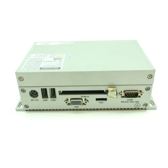
Chapter 2 Hardware Functionality 2.1 UNO-2059E Peripherals The following two figures show the connectors on UNO-2059E. The following sections give you detail information about function of each peripheral. Figure 2.1: UNO-2059E Front Panel Figure 2.2: UNO-2059E Rear Panel 2.2 COM1~COM2: RS-232/485 Interfaces The UNO-2059E offers two RS-232/485 serial communication interface ports, and they are COM1 and COM2. -
Page 15: Com3~Com4: Rs-232/422/485 Interfaces
COM3 RS-422/485 COM4 RS-422/485 16C954 UARTs with 128-byte standard Advantech UNO-2059E comes standard with Oxford OX16PCI964 UARTs containing 128 bytes FIFOs. These upgraded FIFOs greatly reduce CPU overhead and are an ideal choice for heavy multitasking environments. Jumpless for RS-422/485 In RS-422/485 mode, UNO-2059E automatically sense signals to match RS-422 or RS-485 network. -
Page 16: Lan: Ethernet Connector
2.4 LAN: Ethernet Connector The UNO-2059E is equipped with Realtek RTL8100BL Ethernet LAN controller that is fully compliant with IEEE 802.3u 10/100Base-T CSMA/CD standards. The Ethernet port provides a standard RJ-45 jack on board, and LED indicators on the front side to show its Link (Yellow LED) and Active (Green LED) status. -
Page 17: Pcmcia: Pc Card Slot
2.9 PCMCIA: PC Card Slot The UNO-2059E provides one PC Card slot that supports CardBus (Card-32) Card and 16-bit (PCMCIA 2.1/JEIDA 4.2) Card standard. It supports +3.3 V, +5 V and +12 V @ 120 mA working voltage. PC Card is a 85.6 mm long by 54 mm wide (3.37" x 2.126") sized, 68-pin connector used and removable module standardized by PCMCIA that is known as “PCMCIA card.”... -
Page 18: Table 2.4:Programmable Led Control Bit
LED and Buzzer Control Register LEDEn: Enable LED flickering LEDS0 and LEDS1: LED flickering speed setting bit SPKEn: Enable buzzer alarming SPKS0 & SPKS1: Buzzer alarming setting bit Table 2.4: Programmable LED Control Bit LED Flickering Status LEDS1 LEDS2 Light on Fast flicker Normal flicker Short flicker... - Page 19 Initial Setup This chapter shows how to initialize the UNO-2059E, sections include: Sections include: • Inserting the CompactFlash Card • Chassis grounding • Connecting the Power • BIOS Setup and System Assignments...
-
Page 20: Chapter 3 Initial Setup
Chapter 3 Initial Setup 3.1 Inserting CompactFlash Card The procedure for installing a CompactFlash card into the UNO-2059E is as follow, please follows these steps carefully. Step 1: Remove the power cord. Step 2: Unscrew four screws from the rear panel of the UNO-2059E. Step 3: Remove the rear panel. -
Page 21: Connect The Power
3.4 BIOS Setup and System Assignments UNO-2059E adopts Advantech SOM-2354 CPU module. For UNO- 2059E BIOS setup and system assignments, you can refer to SOM-2354 Chapter 4 “Award BIOS Setup” and Appendix A “System Assignments”... - Page 22 UNO-2059E User Manual...
-
Page 23: Pin Assignments
Pin Assignments This appendix gives the UNO-2059E pin assignments Sections include: • Board Connectors & Jumpers • RS-232/485 Serial Port • RS-232/422/485 Serial Port • Ethernet RJ-45 Connector • Phoenix Power Connector • 5V Power Output Connector • PS/2 Keyboard and Mouse Connector •... -
Page 24: Appendix A Pin Assignments
Appendix A Pin Assignments A.1 Board Connectors & Jumpers There are connectors and jumpers on the UNO-2059E board. The follow- ing sections tell you how to configure the UNO-2059E hardware setting. Figure A-1 and figure A-2 show the locations of UNO-2059E connectors and jumpers. -
Page 25: Table A.1:Uno-2059E Connectors & Jumpers
Table A.1: UNO-2059E Connectors & Jumpers Phoenix power connector 5V power output connector Internal IDE connector Internal CompactFlash card slot VGA DB15 display connector RS-232 serial port (reserved) RS-232 serial port (reserved) CN10 PS/2 keyboard and mouse connector CN11 USB1 connector CN12 USB2 connector CN13... -
Page 26: Rs-232/485 Serial Port (Cn13~Cn14)
A.2 RS-232/485 Serial Port (CN13~CN14) Pin Assignments Table A.2: RS-232/485 Serial Port Pin Assigns RS-232 Signal Name RS-485 Signal Name DATA- DATA+ Note: NC represents “No Connection.” UNO-2059E User Manual... -
Page 27: Figure A.3:Com Port Terminator Resistor Locations
Terminator Resistors Setup for RS-485 The terminal resistors for impedance matching on the UNO-2059E are not installed in the factory. Users can install the resistors with the appropriate resistances according to the UNO-2059E application. Each terminal resistor corresponds to a different channels for DATA+, DATA- lines. -
Page 28: Figure A.5:Rs-485 Wiring Topology
RS-485 Signal Wiring The RS-485 standard supports half-duplex communication. This means that just two wires are needed to both transmit and receive data. Hand- shaking signals (such as RTS, Request To Send) in RS-232 are normally used to control the direction of the data flow and to switch the transmis- sion accordingly. -
Page 29: Figure A.6:Rs-232 Jumper Settings
Jumper Setting for RS-232 Interface: (Default Setting) Figure A.6: RS-232 Jumper Settings Jumper Setting for RS-485 Interface: Figure A.7: RS-485 Jumper Settings A.3 RS-232/422/485 Serial Port (CN15~CN16) Pin Assignments Table A.4: RS-232/422/485 Serial Port Pin Assigns RS-232 RS-422 RS-485 DATA- DATA+ Note: NC represents “No Connection”... -
Page 30: Figure A.8:Com 3&4 Port Terminator Resistors
Terminator Resistor Setup for RS-422/485 The terminal resistors for impedance matching on the UNO-2059E are not installed in the factory. Users can install the resistors with the appro- priate resistances according to the UNO-2059E application. Each termi- nal resistor responds to different channels for RS-422/485 signal lines. Usually, these resistors are needed for both ends of the communication wires and the value of the resistors should match the characteristic imped- ance of the wires used (approximately 120 W or 300 W). -
Page 31: Figure A.9:Terminator Installation
An example of the installation of COM3 is as follows: 120 Ω Figure A.9: Terminator Installation RS-232/422/485 Selection COM3 and COM4 support 9-wire RS-232, RS-422 or RS-485 interfaces, and you can set corresponding jumpers to select serial ports as RS-232 or RS-422/485 interfaces shown in Table A-7. -
Page 32: Table A.8:Auto Flow Control & Master/Slave Mode
RS-485 Auto Flow Control and RS-422 Master/Slave Mode Selection You set the “Auto Flow Control” mode of RS-485 or “Master/Slave” mode of RS-422 by using SW2 DIP switches for each RS-422/485 port. In RS-485, if the switch is set to “Auto”, the driver automatically senses the direction of the data flow and switches the direction of transmission. -
Page 33: Ethernet Rj-45 Connector (Lan1)
A.4 Ethernet RJ-45 Connector (LAN1) Ethernet RJ-45 Connector Pin Assignments Table A.9: Ethernet RJ-45 Connector Pin Assigns 10/100Base-T Signal Name XMT+ XMT- RCV+ RCV- A.5 Phoenix Power Connector (CN1) Phoenix Power Connector Pin Assignments Table A.10: Phoenix Power Connector Pin Assigns Signal Name 18 ~ 48 V A.6 5V Power Output Connector (CN2) -
Page 34: Ps/2 Keyboard & Mouse Connector (Cn10)
A.7 PS/2 Keyboard & Mouse Connector (CN10) PS/2 KB/MS Connector Pin Assignments Table A.11: Keyboard & Mouse Pin Assigns Signal Name KB DATA MS DATA KB CLOCK MS CLOCK A.8 USB Connector (CN11, CN12) USB Connector Pin Assignments Table A.12: USB Connector Pin Assigns Signal Name Cable Color DATA-... -
Page 35: 6-Pin Mini Vga Display Connector (Jp3)
A.9 6-pin Mini VGA Display Connector (JP3) VGA Display Connector Pin Assignments P C B Table A.13: VGA Display Connector Pin Assigns Signal Name H-SYNC GREEN V-SYNC BLUE VGA Adaptor Cable Pin Assignments Table A.14: VGA Adaptor Cable Pin Assigns Signal Name Signal Name GREEN... -
Page 36: Compactflash Master/Slavejumper Setting (Jp1)
Chipset The UNO-2059E uses a AMD CS5535 chipset for its SVGA controller. It supports interlaced and non-interlaced analog monitors (color and mono- chrome VGA) in high-resolution modes while maintaining complete IBM VGA compatibility. Digital monitors (i.e. MDA, CGA and EGA) are NOT supported. -
Page 37: Enhanced Ide Connector (Cn4)
A.11 Enhanced IDE Connector (CN4) You can attach two IDE (Integrated Device Electronics) drives to the UNO-2059E for software installation or system testing. The UNO-2059E has an EIDE connector, designated CN1. Wire number 1 on the cable is red or blue, and the other wires are gray. Connect one end to connector CN1 on the board. - Page 38 UNO-2059E User Manual...
Need help?
Do you have a question about the GX2-400 and is the answer not in the manual?
Questions and answers