Table of Contents
Advertisement
Quick Links
Notice
This document is copyrighted, 1997, by Advantech Co., Ltd. All rights are reserved. Advantech Co., Ltd.
reserves the right to make improvements to the products described in this manual at any time without
notice.
No part of this manual may be reproduced, copied, translated or transmitted in any form or by any means
without the prior written permission of Advantech Co., Ltd. Information provided in this manual is
intended to be accurate and reliable. However, Advantech Co., Ltd. assumes no responsibility for its use,
nor for any infringements upon the rights of third parties which may result from its use.
Acknowledgments
ADAM is a trademark of Advantech Co., Ltd.
IBM and PC are trademarks of International Business Machines Corporation.
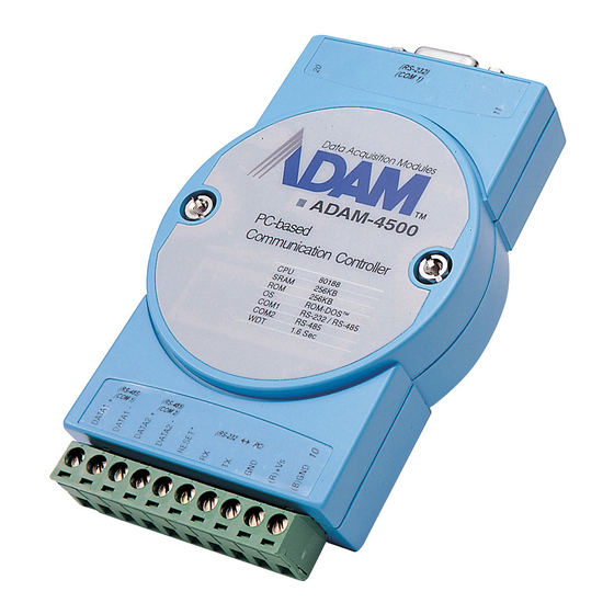
ADAM-4500
PC-based Communication
Controller
User's Manual
Part No. 2050500110
Printed in Taiwan
Copyright
st
1
Edition
July 1997
Advertisement
Table of Contents

Related Manuals for Advantech ADAM-4500


Summary of Contents for Advantech ADAM-4500
- Page 1 User's Manual Copyright Notice This document is copyrighted, 1997, by Advantech Co., Ltd. All rights are reserved. Advantech Co., Ltd. reserves the right to make improvements to the products described in this manual at any time without notice. No part of this manual may be reproduced, copied, translated or transmitted in any form or by any means without the prior written permission of Advantech Co., Ltd.
-
Page 2: Table Of Contents
Step 1:Write and simulate control logic on a PC Step 2:Connect the cables Step 3:Convert and download codes to flash ROM Step 4:Power on ADAM-4500 to complete the application Chapter 4 Function Library Appendix A Register Structure Appendix B Safety Instructions... -
Page 3: Chapter 1 General Information
The watchdog timer is designed to automatically reset the microprocessor when the system fails. This feature greatly reduces the level of maintenance required and makes the ADAM-4500 ideal for use in applications that require a high level of system stability. 1.2 Features •... - Page 4 RS-232 Interface • Signals: TxD, RxD, RTS, CTS, DTR, DSR, DCD, RI, GND • Mode: Asynchronous full duplex, point to point • Connector: DB-9 pin • Transmission speed: up to 115.2 Kbps • Max transmission distance: 50 feet (15.2 m) RS-485 Interface •...
-
Page 5: System Diagram
1.4 System Diagram ADAM-4500 Figure 1-1: ADAM-4500 Diagram... -
Page 6: Chapter 2 Installation Guidelines
2.1 System Requirements to Setup ADAM-4500 The following list gives an overview of what is needed to setup, install and configure an ADAM-4500 system. •... -
Page 7: Steps To Successfully Setup The System
2.2 Steps to Successfully Setup the System Step 1: Review the requirements Before you power on the ADAM-4500, make sure you have a host computer, a power supply, and the utility software and download cable. Step 2: Wiring the power cables and download cable Connect the power cable between the power supply and the ADAM-4500. -
Page 8: Step 3: Run Utility Software In Host Computer
Step 3: Run utility software in host computer Together with the ADAM-4500 you will find a utility disk containing an ADAM4500.EXE file. This file is a menu-driven software utility provided for downloading user's programs. It uses a screen simulating operation of the ADAM-4500 communication controller. When the file is executed, the main screen appears, as shown in figure 2.3. -
Page 9: Step 4: Power On Adam-4500
Figure 2-4: Select Communication Port Step 4: Power on ADAM-4500 Highlight the "Terminal" option, then press <enter>. Power on the ADAM-4500. After 5 seconds, the screen shown in figure 2.5 will appear. The ADAM-4500 system is successfully started up. Figure 2-5: Emulating Screen of ADAM-4500 2.3 Jumper Setting... -
Page 10: Com1 Port Setting
RS-232 Connection The ADAM-4500 has a DB-9 pin connector as its RS-232 port connector. Since the connection for an RS- 232 interface is not standardized, different devices implement the RS-232 connection in different ways. If you are having problems with a serial device, be sure to check the pin assignments for the connector. -
Page 11: Rs-485 Connection
Handshaking signals (such as RTS, Request To Send) are normally used to control the direction of the data flow. A special I/O circuit in the ADAM-4500 automatically senses the direction of the data flow and switches the transmission direction. No handshaking signals are necessary. -
Page 12: Converting Program Codes
Converting Program Codes The ADAM-4500 has an 80188 CPU. Therefore, programs downloaded into its flash ROM must first be converted into 80186 or 80188 compatible code, and the floating point operation must be set to emulation mode. For example, if you were to develop your application program in Borland C, you would compile the program as indicated in the screen below. -
Page 13: Interrupt Types
/* clear WDT timer */ wdt_disable(); /* disable ADAM-4500 WDT function */ Interrupt Types Three types of interrupts may occur in the ADAM-4500. The following table shows the types of interrupts. Interrupt Name Interrupt Type Non-Maskable Interrupt (NMI) COM1 Interrupt... -
Page 14: Preparing The Allfile Directory
Follow the instructions shown on the screen. Power off the ADAM-4500 and then re-power on. Then press any key within 7 seconds to burn the files contained in ALLFILE into the ADAM-4500's flash ROM. After the files are successfully burned into the flash ROM, the screen in Figure 3-3 will appear. Power off and power on the ADAM-4500 once again. -
Page 15: Transferring Files To Sram
Transferring files to SRAM (ADAM-4500's D-drive) The ADAM-4500 provides 234 KB of free SRAM for use in program operation, and as working memory space in the event you want to test your system control logic or simulate system performance before downloading the execution code to the flash ROM. -
Page 16: Steps To Building A Successful Application
ADAM-4500's D drive for testing prior to burning it into the flash ROM. It takes less time to alter and reinstall a program into the SRAM than into the flash ROM, so using the SRAM during debugging on the ADAM-4500 may be more efficient. - Page 17 The function calls included in the directory LIBRARY are described in the following pages. comm_init Syntax: int comm_init(int buf_size) Function description: Initializes the communication port and interrupt routine before other function calls use the communication port. Parameter Description int buf_size Sets the buffer size of every communication port for storage of received data.
- Page 18 int stop Stop bits setting 1, 2 (stop bit = 1 is for data bits = 5,6,7, or 8) (stop bit = 2 is for data bits = 6,7, or 8) For details, refer to RS-232 chip set data book int cmd_type Received data format setting.
- Page 19 Returns a 1 if command succeeds. Returns a 0 if it fails. led_init Syntax: void led_init() Function Description: This function must be called to initialize the ADAM-4500's LED before a user's program can control the LED. Syntax: void led(int type) Function Description:...
-
Page 20: Appendix A Register Structure
This function disables the watchdog timer function. Appendix A Register Structure This appendix gives a short description of each of the ADAM-4500's registers. For more information please refer to the data book for the STARTECH 16C550 UART chip. All registers are one byte in length. Bit 0 is the least significant bit, and bit 7 is the most significant bit. The address of each register is specified as an offset from the port base address (BASE), COM1 is 3F8h and COM2 is 2F8h. - Page 21 BASE+1 Interrupt Status Register (ISR) when DLAB=0 bit 0 Enable received-data-available interrupt bit 1 Enable transmitter-holding-register-empty interrupt bit 2 Enable receiver-line-status interrupt bit 3 Enable modem-status interrupt BASE+2 FIFO Control Register (FCR) bit 0 Enable transmit and receive FIFOs bit 1 Clear contents of receive FIFO bit 2 Clear contents of transmit FIFO...
-
Page 22: Appendix B Safety Instructions
The sound pressure level at the operators position according to IEC 704-1:1982 is equal to or less than 70dB(A). DISCLAIMER: This set of instructions is provided according to IEC 704-1. Advantech disclaims all responsibility for the accuracy of any statements contained therein. - Page 23 - Wenn das Gerät deutliche Anzeichen eines Defektes aufweist. Der arbeitsplatzbezogene Schalldruckpegel nach DIN 45 635 Teil 1000 beträgt 70dB(A) oder weiger. DISCLAIMER: This set of instructions is provided according to IEC704-1. Advantech disclaims all responsibility for the accuracy of any statements contained therein.
Need help?
Do you have a question about the ADAM-4500 and is the answer not in the manual?
Questions and answers