
Related Manuals for Advantech AMAX-1220 Series


Summary of Contents for Advantech AMAX-1220 Series
- Page 1 User Manual AMAX-1220/1240 Series Open Frame 2/4-Axis AMONet RS-485 Motion Slave Modules...
- Page 2 No part of this manual may be reproduced, copied, translated or transmitted in any form or by any means without the prior written permission of Advantech Co., Ltd. Information provided in this manual is intended to be accurate and reliable. How- ever, Advantech Co., Ltd.
- Page 3 This product has passed the CE test for environmental specifications when shielded cables are used for external wiring. We recommend the use of shielded cables. This kind of cable is available from Advantech. Please contact your local supplier for ordering information.
- Page 4 AMAX-1220/1240 Series User Manual...
-
Page 5: Table Of Contents
Contents Chapter Introduction..........1 Features ....................2 AMAX-1220 Specification ................. 2 1.2.1 Axes ....................2 1.2.2 Encoder input................3 1.2.3 Pulse/Direction output..............3 1.2.4 Digital input ................... 3 1.2.5 Digital output ................. 3 1.2.6 Simultaneous move signal ............4 1.2.7 General Specification..............4 AMAX-1240 Specification ................. - Page 6 Motion Control Connector Pin Definition (CN3 to CN9) ......23 2.8.1 External Power Connection and Simultaneous Move Signal (CN3) Table 2.6: External Power Connection and Simultaneous Move Signal (CN3)............. 23 2.8.2 Servo Drive Interface ..............23 Table 2.7: Servo Drive Interface..........24 2.8.3 Mechanical I/O Interface.............
-
Page 7: Chapter 1 Introduction
Chapter Introduction This chapter gives an overview of the product features, and specifi- cations for AMAX-1220/1240 Series. Sections include: Features Specifications... -
Page 8: Features
Products in the AMAX-1220/1240 Series are used to increase the number of axes for an AMONet RS-485 distributed motion control network. These extension slave mod- ules connect serially by a simple and affordable Cat.5 LAN cable, reducing the wiring between driver and controller. This is very suitable for highly integrated machine automation applications. -
Page 9: Encoder Input
1.2.2 Encoder input Item Description Type Two terminal, opto-isolated Encoder Pulse Input Type Quadrature (A/B phase) or Up/Down (CW/CCW) 0: (V+ - V-) < 1V Input voltage 1: (V+ - V-) > 3.5V |V+ - V-| < 15V Max. input voltage Max. -
Page 10: Simultaneous Move Signal
1.2.6 Simultaneous move signal Item Description One terminal, opto-isolated, Type Current sink (5 ~ 30 V) 0: Vo < 0.8 V Output voltage 1: Vo <= Vio CSTA 30 V Max. output voltage CSTP Max. sink current 200 mA per channel Max. -
Page 11: Amax-1240 Specification
AMAX-1240 Specification 1.3.1 Axes Number of 4 Axes Axes Position control Range -134,217,728 ~ +134,217,728 Acceleration/ Deceleration 1 to 65,536 (16-bits) Max: 6.5Mpps Driver Speed Min: 0.1 pps Pulse/Direction (1-pulse, 1-direction type) or Pulse Output Type Up/Down (2-pulse type) or A/B phase Driver Output Pulse Counter1: Command position counter... -
Page 12: Digital Input
1.3.4 Digital input Item Description Type One terminal, opto-isolated 0: Vin < 3 V LMT+, LMT- Input voltage 1: Vin > 10 V INPOS Input Current 4.2 mA @ 24 V 30 V Max. Input voltage Max. Input delay time 100 µs Protection 2,500 V Isolation... -
Page 13: General Specification
1.3.7 General Specification Item Description Bus Type AMONet RS-485 Certifications CE, FCC Class A I/O Connector Type 4*DB26+2*16pin pluggable connector Dimensions 142 x 104 x 45 mm (5.6" x 4.1" x 1.8”) Typical 75mA @ 24V Power Consumption 80mA @ 24V VS: 24 V ±... - Page 14 AMAX-1220/1240 Series User Manual...
-
Page 15: Chapter 2 Hardware Functionality
Chapter Hardware Functionality This chapter shows the hardware functionality of AMAX-1220/1240 Series. Sections include: PCB Board Layout Power Connector AMONet Interface BoardID Switch Configuration Setting LED Definition Pin Definition Signal Connection Field Wiring Considerations... -
Page 16: Pcb Board Layout
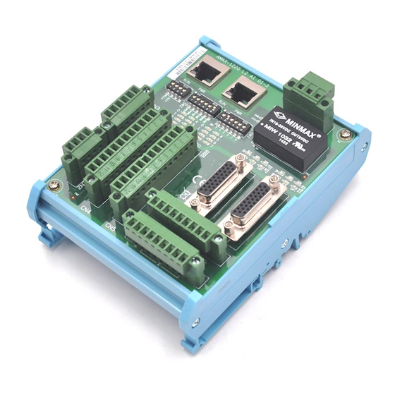
PCB Board Layout 2.1.1 AMAX-1220 PCB Layout & Pin Assignment Figure 2.1 PCB Layout of AMAX-1220 AMAX-1220/1240 Series User Manual... - Page 17 Figure 2.2 Top View of AMAX-1220 Figure 2.3 Middle View of AMAX-1220 AMAX-1220/1240 Series User Manual...
- Page 18 Note! The height does not include the male connector. The height of male connector is 9mm Figure 2.4 Bottom View of AMAX-1220 Figure 2.5 Side View of AMAX-1220 AMAX-1220/1240 Series User Manual...
- Page 19 For Connectors Name Description Module Power External Power and EMG Input Sharing External Power and CSTA, CSTP Input 12 pin pluggable connector 12 pin pluggable connector DB26 Connector for X axis DB26 Connector for Y axis 9 pin pluggable connector for X axis 9 pin pluggable connector for Y axis Board ID Switch Configuration Setting...
-
Page 20: Amax-1240 Label Assignment
2.1.2 AMAX-1240 Label Assignment Figure 2.6 PCB Layout of the AMAX-1240 L2 AMAX-1220/1240 Series User Manual... - Page 21 Figure 2.7 Top View of AMAX-1240 L2 Figure 2.8 Middle View of AMAX-1240 L2 AMAX-1220/1240 Series User Manual...
- Page 22 Note! The height does not include the male connector. The height of male connector is 9mm Figure 2.9 Bottom View of AMAX-1240 L2 Figure 2.10 Side View of AMAX-1240 L2 AMAX-1220/1240 Series User Manual...
- Page 23 For Connectors Name Description Module Power External Power and EMG Input Sharing External Power and CSTA, CSTP Input DB26 Connector for X axis DB26 Connector for Y axis DB26 Connector for Z axis DB26 Connector for U axis 16 pin pluggable connector for X and Y axis 16 pin pluggable connector for Z and U axis Board ID Switch Configuration Setting...
-
Page 24: Power Connector
Power Connector 2.2.1 Module Power Connector (CN1) Table 2.1: Module Power Connector (CN1) Name Type Pin description Power +24V power input Power Power ground VE_GND Power External earth ground 2.2.2 External Power Connector (CN2) Table 2.2: External Power Connector (CN2) Name Type Pin description... -
Page 25: Amonet Interface
AMONet Interface 2.3.1 AMONet Extension Table 2.3: AMONet Extension Label Description Field Ground Field Ground RS485+ High Speed RS-485 protocol Field Ground Field Ground RS485- High Speed RS-485 protocol Field Ground Field Ground Figure 2.11 RS-485 Extension Port AMAX-1220/1240 Series User Manual... -
Page 26: Terminal Resistor
2.3.2 Terminal Resistor Table 2.4: Terminal Resistor 100 1/4W Resistor Note! Terminal Resistor is used for the last module only. Board ID Setting (SW1) SW1 is used to assign the ID occupation in network. AMAX-1240 will ONLY occupy 1 ID by node number setting, but AMAX-1220 will occupy 4 consecutive ID by node number setting. -
Page 27: Communication Protocol Baud Rate Setting (Sw2)
Communication Protocol Baud Rate Setting (SW2) Swtich Label Description SPD1 Baud-Rate Setting SPD0 Time-Out Status Latch Specify watchdog timer time *For internal use only, please keep in OFF Emergency stop control 2.5.1 Baud-Rate Setting SPD1 SPD0 20 MHz 10 MHz 5 MHz 2.5 MHz 2.5.2... -
Page 28: End Limit Logic Setting (Sw3)
End Limit Logic Setting (SW3) For AMAX-1220 Name Type Pin description ELLX ON: High active OFF: Low active ELLY ON: High active OFF: Low active For AMAX-1240 Name Type Pin description ELLX ON: High active OFF: Low active ELLY ON: High active OFF: Low active ELLZ ON: High active OFF: Low active ELLU... -
Page 29: Motion Control Connector Pin Definition (Cn3 To Cn9)
Motion Control Connector Pin Definition (CN3 to CN9) 2.8.1 External Power Connection and Simultaneous Move Signal (CN3) Table 2.6: External Power Connection and Simultaneous Move Signal (CN3) Name Type Pin description +VEX Power External +24V power input +VEX Power External +24V power input -VEX Power External power ground... - Page 30 Table 2.7: Servo Drive Interface Name Axis Type Pin Description SRVON Servo ON output INPOS Servo in position input Servo counter clear output Servo ready input Pulse command differential output - CW- / PULS- 1.Pulse+ output in 2 pulse mode 2.Pulse output in pulse/direction mode Pulse command differential output + CW+ / PULS+...
-
Page 31: Mechanical I/O Interface
2.8.3 Mechanical I/O Interface For AMAX-1220, CN8 and CN9 are defined as follows with TB9 connector type. Name Axis Type Pin Description +VEX Power External +24V power input Home input / General input 3 LMT+ +Direction limit input LMT- -Direction limit input Encoder counter position latch Slow down velocity COMP... -
Page 32: Extra General Purpose Input & Output (Only Available For Amax-1220 Model)
2.8.4 Extra General Purpose Input & Output (ONLY available for AMAX-1220 model) The extra general purpose input and output are defined in CN4 & CN5 of AMAX-1220 with TB12 connector type. Table 2.8: CN4 Name Axis Type Pin Description VCOM Power External common power input Isolated digital input... -
Page 33: Motion Signal Connection
Motion Signal Connection 2.9.1 Digital Input This includes ORG, LMT+, LMT-, LTC, SD, ALM, INPOS, RDY and EMG signals. Home Position Table 2.10: ORG Pins Label Description ORG Input End Limit Table 2.11: LMT+ and LMT- Pins Label Description LMT+ Plus End Limit LMT- Minus End Limit... -
Page 34: Digital Output
Servo In position Table 2.15: INP Pins Label Description INPOS Servo In position Input Servo Ready Table 2.16: RDY Pins Label Description Servo Ready Input Emergency Stop Table 2.17: EMG Pins Label Description Emergency Stop 2.9.2 Digital Output This includes COMP, BREAK, SRVON, ERC and ALMCLR signals. Position Compare for Trigger Output Table 2.18: CMP Pins Label... -
Page 35: Digital Bi-Direction Simultaneously Move Signal
Servo On Table 2.20: SVON Pins Label Description SRVON Servo On control output Reset Driver Error counter/Deviation Counter Clear Table 2.21: ERC Pins Label Description Reset Drive Error Counter Reset Servo Alarm Table 2.22: RALM Pins Label Description ALMCLR Reset Servo Alarm 2.9.3 Digital Bi-direction Simultaneously Move Signal CSTA (Concurrent Start) - Page 36 CSTA/CSTP module connections are up to 8 modules at maximum. In shorts, in the AMONET network (in one ring), no matter AMAX-1240 using CSTA/CSTP or AMAX- 1220 using CSTA/CSTP, there are totally 8 modules in maximum. Table 2.23: CSTA Pins Label Description CSTA...
-
Page 37: Pulse Output Signal
2.9.4 Pulse Output Signal OUT and DIR (Pulse Train Output Control) Table 2.25: DDA Pulse Pins Label Description CW+/PULS+ CW+ / Pulse Output+ CW-/PULS- CW- / Pulse Output- CCW+/DIR+ CCW+ / Direction Output+ CCW-/DIR- CCW- / Direction Output- Encoder Feedback Signal Table 2.26: Encoder Pins Label Description... - Page 38 DO0~DO7 These ports can be control by master card and it can connect relay, SCR and so on. Table 2.28: IDOx Pins Label Description DO0~DO7 General Purpose Digital Output with diamagnetic diode AMAX-1220/1240 Series User Manual...
- Page 39 AMAX-1220/1240 Series User Manual...
- Page 40 No part of this publication may be reproduced in any form or by any means, electronic, photocopying, recording or otherwise, without prior written permis- sion of the publisher. All brand and product names are trademarks or registered trademarks of their respective companies. © Advantech Co., Ltd. 2012...
Need help?
Do you have a question about the AMAX-1220 Series and is the answer not in the manual?
Questions and answers