Table of Contents
Advertisement
Quick Links
Advertisement
Table of Contents

Subscribe to Our Youtube Channel
Related Manuals for Advantech MVP-3245 Series


Summary of Contents for Advantech MVP-3245 Series
- Page 1 User Manual MVP-3245 Series 4-Axis Embedded Motion Controller...
- Page 2 Copyright The documentation and software included with this product are copyrighted 2017 to Advantech Co., Ltd. All rights are reserved. Advantech Co., Ltd. reserves the right to make improvements on the products described in this manual at any time without notice.
- Page 3 Because of Advantech's high quality-control standards and rigorous testing, most of our customers never need to use our repair service. If an Advantech product is defec- tive, it will be repaired or replaced at no charge during the warranty period. For out- of-warranty repairs, you will be billed according to the cost of replacement materials, service time, and freight.
- Page 4 This product has passed the CE test for environmental specifications when shielded cables are used for external wiring. We recommend using shielded cables, which are available from Advantech. Please contact your local supplier for ordering information. FCC Class A This equipment has been tested and found to comply with the limits for a Class A dig- ital device, pursuant to Part 15 of the FCC rules.
- Page 5 Safety Instructions Read these safety instructions carefully. Retain this user manual for later reference. Disconnect the equipment from any AC outlet before cleaning. Use a damp cloth. Do not use liquid or spray detergents for cleaning. For plug-in equipment, the power outlet socket must be located near the equip- ment and must be easily accessible.
- Page 6 MVP-3245 User Manual...
-
Page 7: Table Of Contents
Contents Chapter Overview..........1 Introduction ....................2 Hardware Specifications ................2 1.2.1 System ..................2 1.2.2 Motion Control Interface..............3 1.2.3 I/O Connector................4 Safety Precautions ..................4 Dimensions ....................5 Figure 1.1 Top View of the MVP-3245......... 5 Figure 1.2 Front View of the MVP-3245 ........5 Figure 1.3 Left View of the MVP-3245......... - Page 8 3.1.13 Position Window Output [CAM-DO]..........21 Figure 3.7 Circuit Diagram of Position Window Output ..... 22 3.1.14 Activate Servo ON [SVON] ............22 3.1.15 Servo Error Counter Clear [ERC] ..........22 3.1.16 Position Compare Output [CMP] ..........22 3.1.17 JOG and MPG ................22 Figure 3.8 Circuit Diagram of JOG and MPG ......
-
Page 9: Chapter 1 Overview
Chapter Overview MVP-3245 Specifications Sections: Introduction Hardware Specifications Safety Precautions Dimensions Packing List... -
Page 10: Introduction
Additionally, its design is based on Common Motion API architecture, which uses a unified API. Programmers can integrate any Advantech SoftMotion motion controller without major modification of any code, thus enabling convenient maintenance and upgrades. -
Page 11: Motion Control Interface
Power Typical 24W MAX (1A @ 24V) Consumption Operating Operating 0 ~ 50°C(14 ~ 122°F) @ 5 ~ 85% relative humidity with air Temperature flow) Storage -20 ~ 85°C Relative 5 ~ 95% RH, noncondensing (refer to IEC 68-2-3) Humidity 1.2.2 Motion Control Interface 1.2.2.1... -
Page 12: I/O Connector
Protection 2,500 V isolation 1.2.2.5 Digital Output Item Description Channel SVON, ERC, CMP, CAM-DO Output Voltage 10 V High 30 V Maximum Sink Current 100 mA / channel Protection 2,500 V isolation 1.2.3 I/O Connector 1.2.3.1 Digital Input Item Description Channel Input Voltage Max 2 V... -
Page 13: Dimensions
Note! Connect a protection device to the power input port if the DC voltage is provided by an external circuit. Dimensions Figure 1.1 Top View of the MVP-3245 Figure 1.2 Front View of the MVP-3245 MVP-3245 User Manual... - Page 14 Figure 1.3 Left View of the MVP-3245 MVP-3245 User Manual...
-
Page 15: Packing List
Figure 1.4 Right View of the MVP-3245 Packing List The following items are included in the MVP-3245 accessory box: 1 x 2-pin power supply wiring connector 1 x user manual 1 x warranty card If any of these items are missing or damaged, contact your distributor or sales repre- sentative immediately. - Page 16 MVP-3245 User Manual...
-
Page 17: Chapter 2 Hardware Function
Chapter Hardware Function... -
Page 18: Introduction
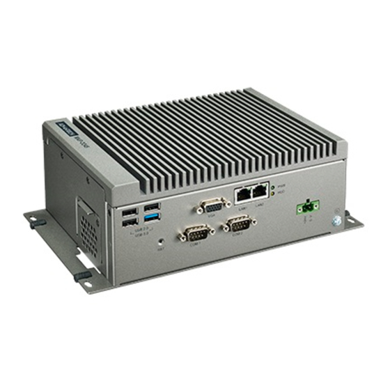
Introduction Front Panel The following figure depicts the front view of the MVP-3245. The connectors are introduced in detail in the following sections. Figure 2.1 Front Panel 2.2.1 Power Supply (PWR) Name Type Description Input +24-V input Output Ground MVP-3245 User Manual... -
Page 19: Communication Connector (Com1 ~ Com2)
2.2.2 Communication Connector (COM1 ~ COM2) The MVP-3245 has two standard RS-232 serial communication connectors, labeled as COM1 and COM2. Please refer to the following pin table: Description 422TX-/485D-/DCD 422TX+/485D+/RX 422RX+/TX 422RX-/DTR Note! COM1 and COM2 of the MVP-3245 enclosure correspond to COM3 and COM4 of the BIOS layer, respectively. -
Page 20: Ethernet (Lan)
2.2.3 Ethernet (LAN) The MVP-3245 has two Ethernet ports compliant with the IEEE 802.3u 10/100/1000 Base-T standard. The LED indicator is green when the system is in communication mode and yellow when it is in operation mode. 2.2.4 Display Port (VGA) 2.2.5 Serial Port (USB) MVP-3245 provides 3 USB-2.0 and 1 USB-3.0. -
Page 21: Rear Panel
Rear Panel The following figure depicts the rear view of the MVP-3245. The motion control con- nectors and I/O control connectors are introduced in details in the following sections. Figure 2.2 Rear Panel 2.3.1 Motion Control (SCSI 100-pin) The MVP-3245 has a SCSI 100-pin (female) motion connector for connecting acces- sories via a shielded cable. - Page 22 MVP-3245 User Manual...
-
Page 23: Chapter 3 Motion And I/O Control
Chapter Motion and I/O Control... -
Page 24: Motion Control Interface
Motion Control Interface The MVP-3245 has a SCSI 100-pin female motion connector (CN1). Advantech sup- plies a comprehensive range of accessories, including the following: Wiring cable for connecting to wiring board PCL-10251: 100-pin to 2 x 50-pin shielded cable. ... -
Page 25: Pin Assignment
3.1.1 Pin Assignment Figure 3.1 shows a pin assignment chart for the SCSI 100-pin connector. The corre- sponding connector descriptions are shown in Table 3.1. Figure 3.1 Pin Assignment Chart for the MVP-3245 Motion Control Connector MVP-3245 User Manual... - Page 26 Table 3.1: Description of I/O Connector Signal Signal Name Reference Direction Description Input External power (24 V Input Emergency stop (for all axes) LMT+ Input +Direction limit Input -Direction limit Input Position latch Input Servo ready Input Position latch Input In-position signal Input Servo alarm...
-
Page 27: Jumper Setting
3.1.2 Jumper Setting On the MVP-3245, CN24 (axis X), CN25 (axis Y), CN26 (axis Z), and CN27 (axis U) can be configured via jumper settings. The circuit shown in Figure 3.3 (with the first two rows of CN24-CN27 short-circuited) is set to differential output mode as default. To switch to single-ended output mode, simply change the jumper connector. -
Page 28: Traveling Limit Switch Input [Lmt+/-]
Figure 3.3 Line Drive Interface 3.1.4 Traveling Limit Switch Input [LMT+/-] Traveling limit switches are used to protect the system. This input signal is connected via the photocoupler and RC filter. When the limit switch is applied, the external VEX 12 ~ 24 V will be the power source of the photocoupler. -
Page 29: Servo Error And Alarm [Alm]
3.1.9 Servo Error and Alarm [ALM] This input is from the servo drive, which will generate an alarm signal in the event of an operation error. 3.1.10 Encoder Input [ECA+/-, ECB+/-, ECZ+/-] When the feedback encoder signals arrive, ECA+/ECA- is connected to phase A of the encoder output. -
Page 30: Activate Servo On [Svon]
Figure 3.7 Circuit Diagram of Position Window Output 3.1.14 Activate Servo ON [SVON] This SVON generates a digital output to activate the servo drive to be ready for move status. 3.1.15 Servo Error Counter Clear [ERC] The signal to clear the deviation counter is generated by the servo drive, and the board can receive it as a general purpose input. -
Page 31: Digital Input
3.1.18 Digital Input The following wiring mode is recommended for external digital inputs: (a) General optical isolated digital input 3.1.19 Digital Output The following wiring mode is recommended for external digital outputs: (a) Connect optical isolated digital outputs to the external general load (b) Connect optical isolated digital outputs to the external lagging load MVP-3245 User Manual... -
Page 32: Pin Assignment Of I/O Control Connector
Pin Assignment of I/O Control Connector The MVP-3245 has a D-Sub 37-pin female I/O connector (CN2). Advantech provides a comprehensive range of accessories including the following: Wiring cable for connecting to wiring board PCL-10137: 37-pin shielded cable Wiring board ADAM-3937: D-sub 37-pin wiring board ... - Page 33 MVP-3245 User Manual...
- Page 34 No part of this publication may be reproduced in any form or by any means, such as electronically, by photocopying, recording, or otherwise, without prior written permission of the publisher. All brand and product names are trademarks or registered trademarks of their respective companies. © Advantech Co., Ltd. 2017...
Need help?
Do you have a question about the MVP-3245 Series and is the answer not in the manual?
Questions and answers