
Related Manuals for Advantech AMAX-5580


Summary of Contents for Advantech AMAX-5580
- Page 1 User Manual AMAX-5580 High Performance DIN-Rail PC Controller w/ 2xGbE, 1 x mPCIe, 4 x USB, VGA, HDMI...
- Page 2 No part of this manual may be reproduced, copied, translated or transmitted in any form or by any means without the prior written permission of Advantech Co., Ltd. Information provided in this manual is intended to be accurate and reliable. How- ever, Advantech Co., Ltd.
- Page 3 Because of Advantech’s high quality-control standards and rigorous testing, most of our customers never need to use our repair service. If an Advantech product is defec- tive, it will be repaired or replaced at no charge during the warranty period. For out- of-warranty repairs, you will be billed according to the cost of replacement materials, service time and freight.
- Page 4 Technical Support and Assistance Visit the Advantech web site at www.advantech.com/support where you can find the latest information about the product. Contact your distributor, sales representative, or Advantech's customer service center for technical support if you need additional assistance. Please have the following information ready before you call: –...
- Page 5 The sound pressure level at the operator's position according to IEC 704-1:1982 is no more than 70 dB (A). DISCLAIMER: This set of instructions is given according to IEC 704-1. Advantech disclaims all responsibility for the accuracy of any statements contained herein.
- Page 6 AMAX-5580 User Manual...
-
Page 7: Table Of Contents
Figure 2.2 Power System of AMAX-5000 ........7 Configuration of CPU Module, AMAX-5580 ..........8 Figure 2.3 Front View of AMAX-5580 .......... 8 Table 2.1: Legend of configuration of AMAX-5580 CPU module 8 Figure 2.4 Internal configuration under the front cover of AMAX- 5580................9 Table 2.2: Legend of configuration inside AMAX-5580 CPU mod-... - Page 8 5.3.3 Pin Assignments (PB9 Male) ............45 Figure 5.12AMAX-5495 COM1/COM2 Pin-out......45 5.3.4 Advantech Device Manager / Driver Installation......46 Figure 5.13Driver Installation Step1 ........... 46 Figure 5.14Driver Installation Step2 ........... 47 Figure 5.15Driver Installation Step3 ........... 47 AMAX-5410 2-port GigE Vision Frame Grabber Module ......48 Figure 5.16AMAX-5410 Module ..........
- Page 9 Table A.3: USB 3.0 Connector Pin Assignments....... 57 AMAX-5580 HDMI Display Connector ............ 57 Table A.4: HDMI Display Connector .......... 57 AMAX-5580 EtherCAT Connector (Between IO Modules)...... 58 Table A.5: EtherCAT Connector ..........58 AMAX-5580 LED Indicators ..............59 Table A.6: PWR LED ..............59 Table A.7: SATA LED ..............
- Page 10 AMAX-5580 User Manual...
- Page 11 Chapter Introduction...
-
Page 12: Chapter 1 Introduction
AMAX-5580 supports dual display VGA and HDMI for various high resolution require- ments. The AMAX-5580 can operate in wide temperature ranges from -10 to 60 °C. The AMAX-5580 leverages Intel’s Skylake series Core i CPU structure and support dual bank DDR4 which can support up to maximum 32GB RAM capability. AMAX-5580 CPU unit provides expansion including 1 x Mini-PCIe and a single internal USB port. -
Page 13: Accessories
Accessories Please refer below for the accessory list: Power Connector (Advantech P/N: 1652008020-01) If anything is missing or damaged, contact your distributor or sales representative immediately. Product Specifications 1.4.1 AMAX-5580 System Specifications General – Certification: CE, FCC, UL –... - Page 14 Storage Temperature: -40 ~ 85°C (-40 ~ 185°F) – Relative Humidity: 10 ~ 95% RH @ 40°C, non-condensing – Shock Protection: Operating, IEC 60068-2-27, 10G, half sine, 11 ms – Vibration Protection: Operating, IEC 60068-2-64, 1 Grms, random, 5 ~ 500 Hz, 1hr/axis (M.2) AMAX-5580 User Manual...
-
Page 15: Chapter 2 Amax-5000 System Overview
Chapter AMAX-5000 System Overview... - Page 16 Two serial COM port (RS-232/RS-485/RS-422) The AMAX-5580 Basic CPU module equips with 4 PCIe lanes for left hand side func- tion extension, first attached module can use the PCIe x4 resource and the other 3 use PCIe x1 resource. The supported functions include USB 3.0, PoE, GbE, RS-232/ 422/485, Flash Disk and Wireless Interface.
- Page 17 /analytics, or even vision inspection integration. With full function sup- port of SDK/API in C/C++ and C#. NET environment, user can implement the algo- rithm easily and communicate the data with other node or cloud services. AMAX-5580 User Manual...
-
Page 18: Configuration Of Cpu Module, Amax-5580
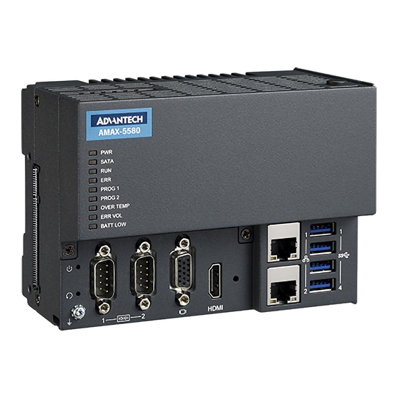
Configuration of CPU Module, AMAX-5580 Figure 2.3 Front View of AMAX-5580 Table 2.1: Legend of configuration of AMAX-5580 CPU module Component Description Connection for EtherCAT Slice IO extension EtherCAT Slice Connection modules. Interfaces for peripherals such as mouse, USB Interface keyboard or USB memory. - Page 19 Figure 2.4 Internal configuration under the front cover of AMAX-5580 Table 2.2: Legend of configuration inside AMAX-5580 CPU module Component Description To install M.2 SSD for operation system M.2 Connector (M Key) installation. RTC Battery Battery to keep RTC and BIOS settings...
-
Page 20: Module Overview
Module Overview 2.2.1 AMAX-54XX PCIe Expansion Module AMAX-5580 provide PCIe extension interface from the left-hand side, and there are following modules available: Table 2.3: Table 3: List of AMAX-54XX series extension modules Model Front View Description Wireless Expansion Module -PCIe-mini Card Slot (full-size) inside for AMAX-5400E Advantech EWM module installation. -
Page 21: Amax-50Xx Ethercat I/O Modules
2.2.2 AMAX-50XX EtherCAT I/O Modules The right-hand side of AMAX-5580 is the interface for the EtherCAT Slice IO mod- ules. Below is the table for the current supported IO modules: Table 2.4: List of AMAX-50XX series extension modules Model Description... - Page 22 *This module is with power input, no need AMAX-5001 on the right side EtherCAT Bus Extender AMAX-5079 -Extend EtherCAT by RJ45 With the PCIe and EtherCAT interface, AMAX-5580 can optionally equip some func- tion module to fulfill application requirements. Below are examples: Vision + Motion Controller ...
-
Page 23: Concentrator
24VDC Power input module for AMAX-5000 slice IO, include 4DI AMAX-50XX AMAX-5000 Slice IO to fulfill the IO requirement of the station AMAX-5079 Extend EtherCAT to next station AMAX-5074 EtherCAT bus coupler AMAX-50XX AMAX-5000 Slice IO to fulfill the IO requirement of the station AMAX-5580 User Manual... -
Page 24: Cpu Types
CPU Types Control IPC Barebone AMAX-5580 is a Control IPC barebone system for users to configure according to their application. Users can install a supported OS and get driver support from the Advantech website. However, we suggest users to order an embedded OS from Advantech which are optimized OS images configured for the best performance. -
Page 25: Cpu Architecture
(High Speed Slot ) PCIex1 SATA (P2) DDI DDI PCIex1 Intel Slice IO Port 2 Port 1 i210AT Super IO USB 2.0 M.2 (Key M) PCIe Switch PCIe‐mini Card Slot (NVRAM installed) Intel i210AT COM1/2 HDMI USB 3.0 Figure 2.7 System Architecture of AMAX-5580 Note! LAN2 and PCIe-mini Card Shared Resource AMAX-5580 User Manual... - Page 26 AMAX-5580 User Manual...
-
Page 27: Chapter 3 Initial Setup
Chapter Initial Setup... -
Page 28: Selecting The Right Power Supply Unit
Selecting the Right Power Supply Unit The AMAX-5580 needs an external 24VDC power input from the screw terminal on the top. And this power input will supply power to the main CPU module (AMAX- 5580) and left-hand-side PCIe expansion modules (AMAX-54XX).The pin definition is as below: Table 3.1: Pin Definition of Power Input Terminal... -
Page 29: System Configuration And Installation
LED is on. Please make sure power is completely off and every LED is off before changing hardware. To enhance the system availability, AMAX-5580 provides dual power input functions to support main power input and backup power input. If either power input encoun- ters trouble it will trigger the below alarms: The LED “ERR VOL”... - Page 30 Operation Temperature -40 °C to +85 °C Advantech Part Number 1750199011 Install the USB device in the internal USB2.0 port AMAX-5580 reserves one port inside the chassis for important USB devices. The USB device could be: – USB dongle key for software –...
-
Page 31: Mounting
Note: The CPU module may overheat if the installation position is incorrect or mini- mum distances are not adhered to. AMAX-5580 uses a passive cooling system and does not need a correct mounting position to ensure optimum heat dissipation. Note the below requirements for the control cabinet: Please make sure the temperature of the control cabinet is within the operating temperature of AMAX-5580, which is -10~60 °C... -
Page 32: Attaching On The Din-Rail
3.4.1 How to enter the BIOS? First, plug-in the 24VDC input power to boot the AMAX-5580 or reboot it if it is run- ning. Second, press the “Delete” key while the AMAX-5580 is performing the power- on self-test (POST). If you can hear the “beep” sound from your AMAX-5580 control- ler, you are successfully accessing the BIOS. -
Page 33: Bios Configuration
3.4.2 BIOS configuration When you enter the BIOS, the “Main” tab list overall information to the AMAX-5580 controller; you will see BIOS information and Processor Information on this page. Figure 3.3 BIOS and processor information 3.4.3 Hardware Monitor The “Hardware Monitor” option under “Advanced” tab shows all hardware monitor sensors real-time values. - Page 34 In order to protect your system from overheating; you could also set the “CPU Shutdown Temperature” value. If the CPU overheats, the system will shut down automatically. Figure 3.6 The CPU shutdown temperature and overheating temperature configuration in BIOS AMAX-5580 User Manual...
- Page 35 Like the figure below, users can choose a certain time interval to reboot the system if the computer fails to reset the watchdog. Furthermore, AMAX-5580 also supports numerous Watch Dog Timer API to allow users to build their own applications. For more details, please refer to Chapter 3.6 Advantech Watchdog KMDF Driver.
-
Page 36: Serial Port Configuration
“Advanced” tab and select “Serial Port Config- uration” to enable the serial port and select the protocol type. Figure 3.8 Serial port configuration in BIOS Figure 3.9 Enabling serial port in BIOS AMAX-5580 User Manual... -
Page 37: Save Settings And Return To Default
After configuring the BIOS, please press “F4” key to save the settings and exit the BIOS. If you want to return the setting to default, please press “F3” key to return the opti- mized default setting. Figure 3.11 Hotkey to Optimized Defaults and Save & Exit Setup in BIOS AMAX-5580 User Manual... - Page 38 AMAX-5580 User Manual...
-
Page 39: Software Tools
Chapter Software Tools... -
Page 40: Verinfo
AMAX-5580 controller also has useful utilities and drivers to help you monitor your device or build your own applications for advanced uses. All the utilities and drivers are bundled in the OS image which has already been pre-installed in your AMAX- 5580. -
Page 41: Susi Iot
Susi IOT Advantech Susi IOT provides an interface to have an overview of all system informa- tion on your AMAX-5580 platform. You can find the utility by the following path in AMAX-5580: C:\Program Files\Advantech\SusiIoT\Applications\SusiIoT Demo AMAX-5580 User Manual... -
Page 42: Eapi
The target is to avoid software modifications when changing device modules. EAPI will cover all interfaces in the device to unify the software control: You can find developer guide and sample codes by the following path in AMAX-5580: C:\Program Files\Advantech\PlatFormSDK AdvWF... -
Page 43: Advantech Lmsensor
Windows system platforms. This driver also pro- vides sample applications so you can modify sample code to meet your needs. You can find examples and the user manual by the following the path in AMAX-5580: C:\ Program Files (x86)\Advantech\Lmsensor... -
Page 44: Advantech Watchdog Kmdf Driver
When development work is com- pleted, you can use test tools to verify if functions of your application are working correct. You can find examples and user manual by the following path in AMAX-5580: C:\ Program Files (x86)\Advantech\Watchdog AMAX-5580 User Manual... -
Page 45: Pcie Expansion Module
Chapter PCIe Expansion Module... -
Page 46: Amax-5424V 4-Port Usb3.0 Vision Frame Grabber Module
AMAX-5424V 4-port USB3.0 Vision Frame Grabber Module The AMAX-5424V provides four extra USB3.0 ports to the AMAX-5580 controller. Figure 5.1 AMAX-5424V Module 5.1.1 AMAX-5424V Specification General: Certification CE, FCC class A Connector 4 x USB 3.0 Type A Enclosure Aluminum housing Power Consumption 2.5W@24VDC... -
Page 47: Led Indicator
Environment: Operation Temperature -10~60°C (vertical mounted) Storage Temperature -40~85°C Relative Humidity 5~95% (non-condense) 5.1.2 LED Indicator Figure 5.2 AMAX-5424V Module LED Indicator Color Indication Behavior Green Controller Power on Controller Standby STBY Yellow Connected to DC power AMAX-5580 User Manual... -
Page 48: Amax-5490 2-Port Isolated Rs-232/422/485 Communication Module
5, 6, 7, 8 Stop Bits 1, 1.5, 2 Parity None, even, odd Baud Rate 50 bps ~ 230.4 kbps RS-232: TXD, RXD, GND Data Signals RS-422: TX+, TX-, RX+, RX- RS-485: Data+, Data- FIFO 256 bytes Flow Control Xon/Xoff AMAX-5580 User Manual... -
Page 49: Led Indicator
Figure 5.4 AMAX-5490 Module LED Indicator Color Indication Behavior Green Controller Power on Controller Standby STBY Yellow Connected to DC power Yellow Blink Data is Transmitting Green Blink Data is Receiving Yellow Blink Data is Transmitting Green Blink Data is Receiving AMAX-5580 User Manual... -
Page 50: Com1/Com2 Pin-Out (Pb9 Male)
5.2.3 COM1/COM2 Pin-out (PB9 Male) Figure 5.5 AMAX-5490 COM1/COM2 Pin-out DB9 Pin-out (Male) RS232 RS422 RS485 AMAX-5580 User Manual... -
Page 51: Jumper Switch
Figure 5.6 AMAX-5490 Jumper Switch Jumper Switch Settings SW3 (for COM1) and SW4 (for COM2) are designed for RS232/485/422 interface selection. Figure 5.7 AMAX-5490 SW3/SW4 SW5 is designed for the terminal resistance settings. Figure 5.8 AMAX-5490 SW5 AMAX-5580 User Manual... - Page 52 120Ω Pin3+Pin4 RS485/422 no terminal resistance SW6 is designed for the RS422 master/slave, or RS485 interface selection. Figure 5.9 AMAX-5490 SW6 COM1 RS422 Master Pin1 RS422 Slave / RS485 COM2 RS422 Master Pin2 RS422 Slave / RS485 AMAX-5580 User Manual...
-
Page 53: Amax-5495 2-Port Can Module
AMAX-5495 2-port CAN Module The AMAX-5495 features 2 extension ports for CAN interface, which supports CAN 2.0B Protocol and compatible with CAN 2.0A Protocol. Figure 5.10 AMAX-5495 Module AMAX-5580 User Manual... -
Page 54: Amax-5495 Specification
1, 4, 5, 6, 8, 9 - NC Protection: ESD Protection 8KV (air), 4KV (contact) EFT Protection 2,000 VDC (Power Line) Isolation Protection 2,500 VDC (between COM port and backplane) Environment: Operation -10~60°C (vertical mounted) Temperature Storage Temperature -40~85°C Relative Humidity 5~95% (non-condense) AMAX-5580 User Manual... -
Page 55: Led Indicator
Connected to DC power Yellow Blink Transmitting Data Green Blink Receiving Data Yellow Blink Transmitting Data Green Blink Receiving Data 5.3.3 Pin Assignments (PB9 Male) Figure 5.12 AMAX-5495 COM1/COM2 Pin-out DB9 Pin-out (Male) Signal CAN_N CAN_ISO CAN_P AMAX-5580 User Manual... -
Page 56: Advantech Device Manager / Driver Installation
Advantech provides WDM CAN driver that allows you to configure your hardware and store the settings in your Windows registry. You must install the WDM CAN driver if you want to add and manage Advantech CAN cards. Please follow the steps below to install Advantech CAN WDM Driver. - Page 57 After a while, the installation will be complete. Figure 5.14 Driver Installation Step2 After the physical hardware has been installed, the card will be automatically detected. Figure 5.15 Driver Installation Step3 AMAX-5580 User Manual...
-
Page 58: Amax-5410 2-Port Gige Vision Frame Grabber Module
AMAX-5410 2-port GigE Vision Frame Grabber Module The AMAX-5410 provides two extra GigE interface to the AMAX-5580 controller. Figure 5.16 AMAX-5410 Module AMAX-5580 User Manual... -
Page 59: Amax-5410 Specification
Environment: Operation Temperature -10~60°C (vertical mounted) Storage Temperature -40~85°C Relative Humidity 5~95% (non-condense) 5.4.2 LED Indicator Figure 5.17 AMAX-5410 Module LED Indicator Color Indication Behavior Green Controller Power on Controller Standby STBY Yellow Connected to DC power AMAX-5580 User Manual... -
Page 60: Amax-5410P 2-Port Poe Vision Frame Grabber Module
The AMAX-5410P provides two extra ports of GigE interface with PoE interface to the AMAX-5580 controller. The maximum power is 15W per port; and maximum 20W for entire module DC output to the external PoE devices. The power comes from the internal PCIe bus, so no external power is needed. -
Page 61: Amax-5410P Specification
48 VDC PoE Power output, 15W per port, total Max.20W (AMAX- Output PoE Power 5410P only) Protection: ESD Protection 8KV (air), 4KV (contact) EFT Protection 2,000 VDC Isolation Protection 2,500 VDC Environment: Operation Temperature -10~60°C (vertical mounted) Storage Temperature -40~85°C Relative Humidity 5~95% (non-condense) AMAX-5580 User Manual... -
Page 62: Led Indicator
5.5.2 LED Indicator Figure 5.19 AMAX-5410P Module LED Indicator Color Indication Behavior Green Controller Power on Controller Standby STBY Yellow Connected to DC power Green Port1 is connected Green Port2 is connected AMAX-5580 User Manual... -
Page 63: Amax-5400E Pcie Mini Card Expansion Module
AMAX-5400E PCIe mini card expansion module The AMAX-5400E module provides additional PCIe mini card and SIM card slot to the AMAX-5580 controller. It can be also installed an antenna on the top of the mod- ule to enhance the wireless signal. -
Page 64: Led Indicator
In order to install PCIe mini card and Antenna (if needed), please remove side cover, the PCIe mini card slot and mounting hole's position is shown as below figure. Figure 5.22 AMAX-5400E PCIe mini card installation guide AMAX-5580 User Manual... -
Page 65: Appendix A Pin Assignments
Appendix Pin Assignments... -
Page 66: Amax-5580 Com1/Com2 Rs-232/422/485
AMAX-5580 COM1/COM2 RS-232/422/485 Table A.1: RS-232 Serial Port Pin Assignments Pin Name Table A.2: RS-422/485 Serial Port Pin Assignments RS-422 RS-485 Data- Data+ Please setup the serial port in the BIOS. AMAX-5580 User Manual... -
Page 67: Amax-5580 Usb Connector
StdA_SSRX- SuperSpeed receiver differential pair StdA_SSRX+ GND_DRIAN Ground for signal return StdA_SSTX- SuperSpeed transmitter differential pair StdA_SSTX+ AMAX-5580 HDMI Display Connector Table A.4: HDMI Display Connector Signal Signal TMDS Data2+ TMDS Data2 Shield TMDS Data2- TMDS Data1+ TMDS Data1 Shield... -
Page 68: Amax-5580 Ethercat Connector (Between Io Modules)
AMAX-5580 EtherCAT Connector (Between IO Modules) Table A.5: EtherCAT Connector Signal Name (Input) Signal Name (Input) AMAX-5580 User Manual... -
Page 69: Amax-5580 Led Indicators
AMAX-5580 LED Indicators Table A.6: PWR LED Description ACPI Status Shutdown Green LED Status Flashing Green Orange Table A.7: SATA LED Description SATA Read and Write Not working LED Status Orange Read and Write Table A.8: RUN LED Description User Defined... - Page 70 No part of this publication may be reproduced in any form or by any means, electronic, photocopying, recording or otherwise, without prior written permis- sion of the publisher. All brand and product names are trademarks or registered trademarks of their respective companies. © Advantech Co., Ltd. 2020...
Need help?
Do you have a question about the AMAX-5580 and is the answer not in the manual?
Questions and answers